


usedtosail
-
Posts
2,421 -
Joined
-
Last visited
Content Type
Profiles
Forums
Gallery
Events
Everything posted by usedtosail
-
 Very nice rigging. I like your furled sails too.
- 481 replies
-
- 2
-

-
- rattlesnake
- model shipways
- (and 1 more)
-
Wow, it is really amazing what you have done with plastic, Popeye. You are a man of many mediums, I would say.
- 140 replies
-
- 6
-
-
- jolly roger
- lindberg
- (and 1 more)
-
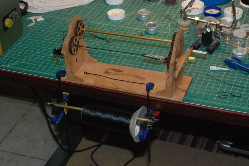
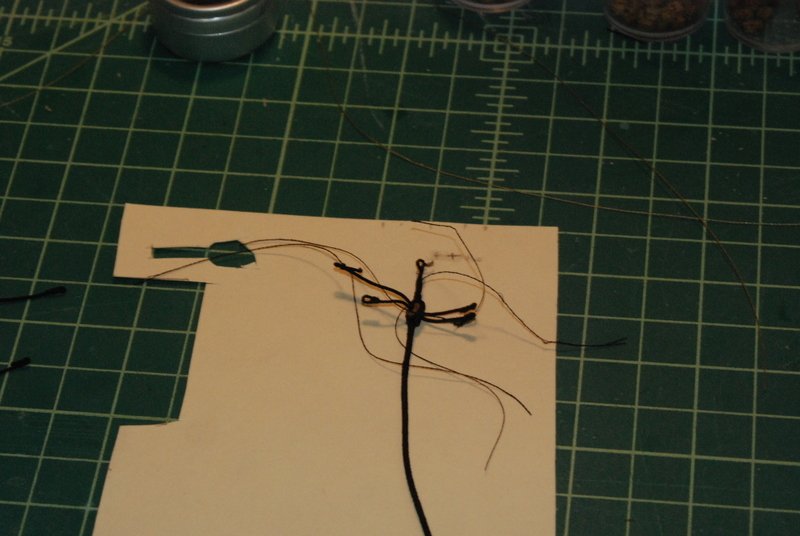
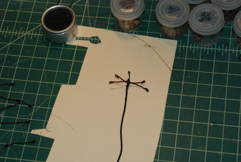
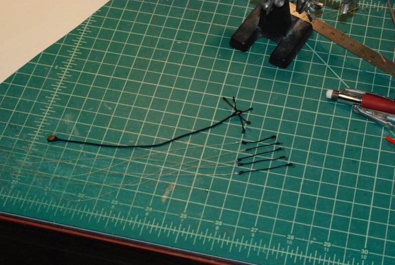
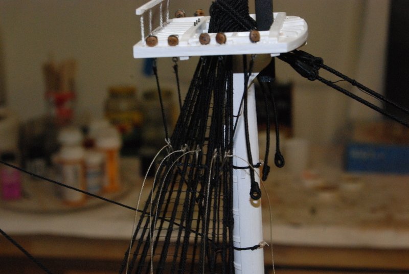
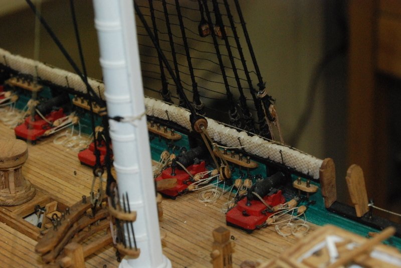
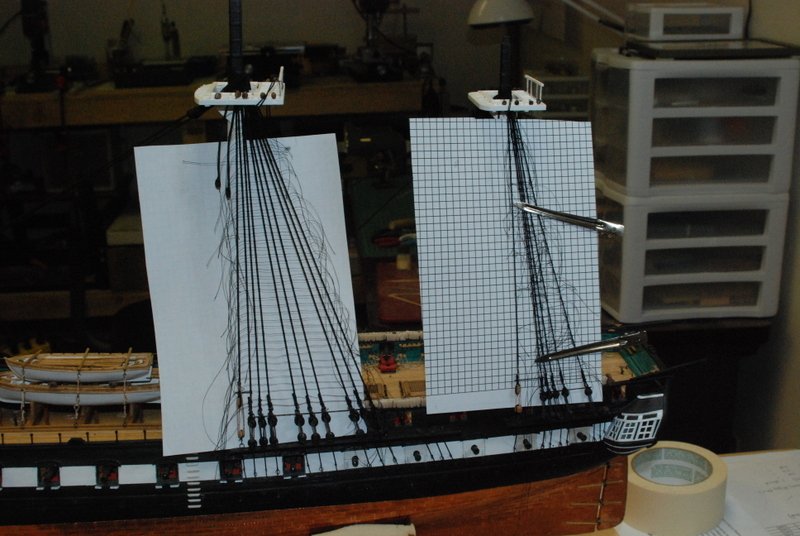
Had a great Father's Day weekend. My wife and I took a tour around Boston harbor Saturday afternoon to view the tall ships which are in town. Saw the Bluenose II and the Pride of Baltimore II, as well as about 20 other large and small sailing ships. Yesterday my son took me out for ice cream and mini golf. But, I did manage to get some time in the shop too, so here is what I have been working on. Bentinck shrouds - The futtock shrouds are usually wrapped around the futtock stave and seized to the lower shrouds on most ships of this period. On the Constitution, however, the futtock shrouds end in a loop that is lashed around the futtock stave and shroud, into a futtock extension on the other side of the shrouds. These extensions have loops on both ends and go through a bullseye at the top of the Bentinck shroud. The Bentinck shrouds have bullseyes on the lower ends that are lashed to a similar bullseye on the waterway. There are a lot of parts to these that require a lot of seizings to make. I think I can do a seizing blindfolded now. Also, all of these lines are served, so I started by serving a long length of black line for the shrouds and extensions. I then seized the bullseyes to the larger shroud lines, and then served them the whole length. I had to drill out the hole in the upper bullseyes so I could get three served lines to fit inside the hole. Note my large spool holder attachment for the Syren Serving Machine. I stropped the two lower bullseyes with hooks, seized in a lashing line, and hooked them into eyebolts I had placed in the waterways months ago: Here are the extensions being added to the shrouds. I made a loop on one end, threaded them through the bullseye, then seized the loop on the other end. I used some tick marks on the top of the card to get them the right length, or as close as I could get. The first picture shows them before I trimmed the loose ends of the seizings. I kind of cheated with the middle extension. it is supposed to be seized to the futtock stave, but instead I seized it to the bullseye, which was a lot easier, as I could do it off the model. The futtock shrouds have a hook on one end, to hook into the stropping of the deadeyes on the fore and main mast tops. The other end is a loop, and I seized a lashing line into each loop. Here are all the parts ready to install (except for the two bullseyes with hooks that I had already installed). Notice how there is a range of sizes for the futtock shrouds, so the loops end up at roughly the same distance from the futtock stave. I installed these by first lashing the center futtock shroud to the center extension, then lashing the two bullseyes at the bottom of the Bentinck shrouds. I adjusted the two lashings until I got the spacing right, then lashed the rest of the futtock shrouds to the other extensions. The lashings go diagonally across the futtock stave, which of course I did not do with the first set, and got to redo them. Once they were all lashed I did a final adjustment then tied off all the lashings. I have left the lashings uncut for now in case I need to redo these, but I will fix the knots with some glue at some point and cut off the excess. Here is the starboard main futtock shrouds and extensions. I didn't get a picture of the extensions from the other side of the shrouds, but I may include one in a future post. And the bottom of the Bentinck shrouds: I still have the port main side to do, but i have most of the pieces ready for them. I will then make and install the mizzen futtock shrouds, which are more traditional and do not use the Bentinck shrouds. As always, thanks for you interest.
- 1,354 replies
-
- 16
-
-
- constitution
- model shipways
- (and 1 more)
-
I am glad you decided to add the gun deck too. When all is said and done, knowing that the details are there is very satisfying. Also, having complete cannons instead of the dummy gun barrels is so much better. Great job so far.
-
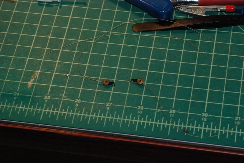
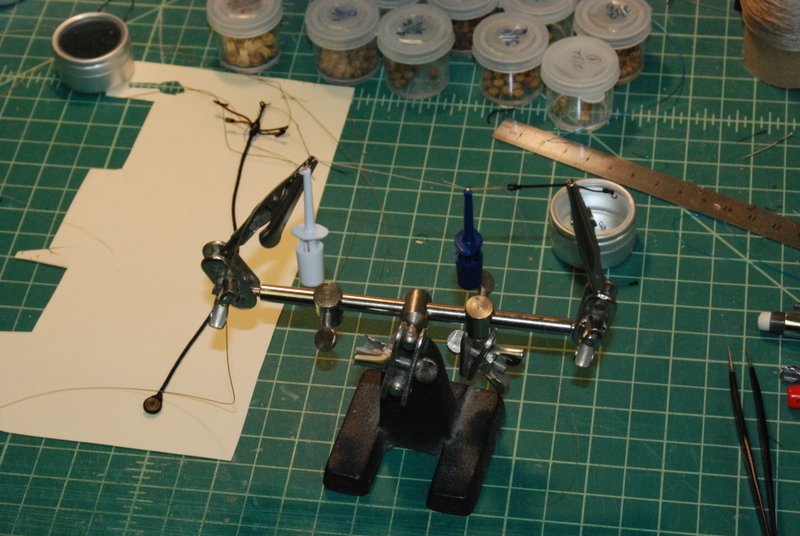
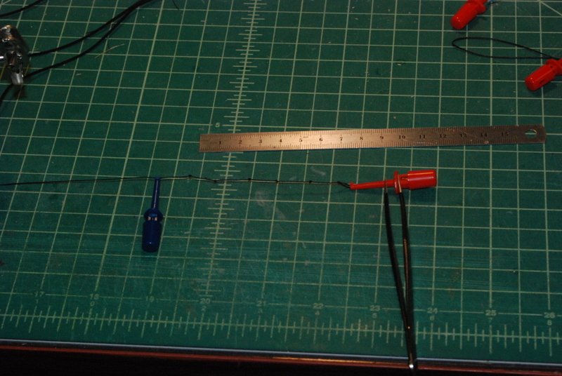
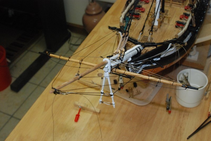
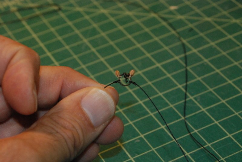
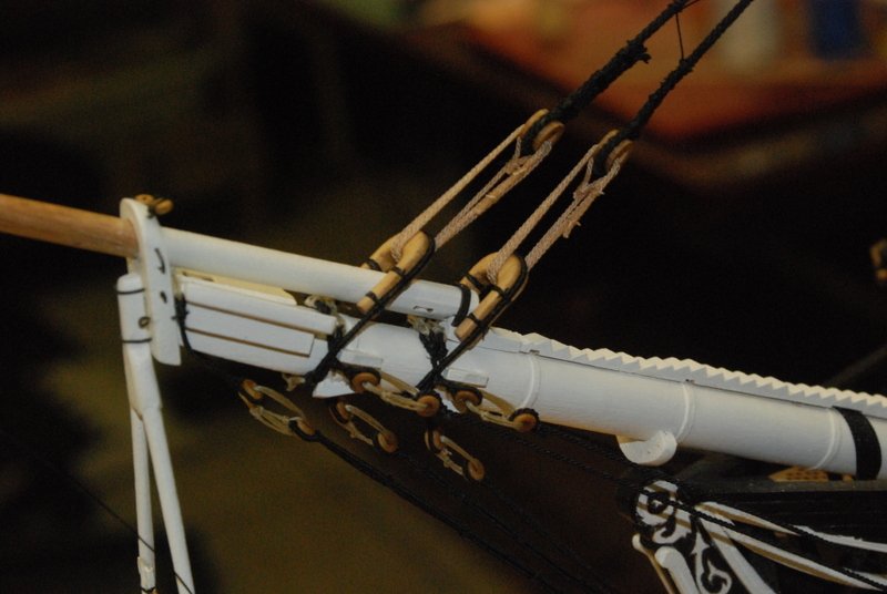
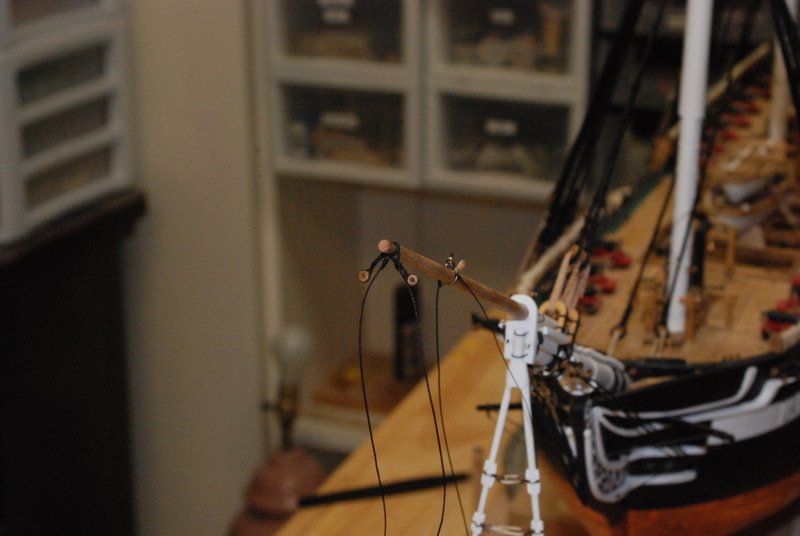
I finished rigging the jibboom, which included rigging the spritsail yard. It has 8 bullseyes on it to direct lines from the bowsprit to the bow pin rail and cathead. Here is a shot while I was installing them.To get them to be parallel with the yard, I first ran a line around the bulleye and seized it, then while the glue on the seizing was drying I twisted a 90 bend at the seizing. After the glue dried the excess lines now ran at 90 degrees to the bullseye, so I just tied them to the yard with an overhand knot and fix it to the yard. I stropped other blocks with loops that fit over the yard arms for the lifts and braces. I added the footropes and one side of the parrel line to hold the yard to the bowsprit, then carefully slid the yard between the second and third bobstays to get it into position. I thought I was going to have to undo the lashing on the third bobstay, but I am glad I waited to try this first. I then tied the other end of the yard parrel. At this point I was able to add the lines from the jibboom that go to the blocks and bullseyes on the cathead, and the martingale stays which are seized to the dolphin striker. I still have a few loose ends to cut and the jibboom footropes to add in this picture, which I have done since I took it. I also tightened the lashing on the starboard fixed guy, which is the line that has that funny bend at the tip of the jibboom. I am finding these electronic test clips invaluable for rigging. Here I am using them to mark the location of the next knot to tie in the jibboom footrope, as well as providing a handle on the other end of the line. They are perfect for holding two lines together while seizing them, and for forming small loops around, as I am doing for the futtock shrouds. And that is what is coming. I have all of the fore futtock shrouds made and the 2 Bentinck shrouds. Now I need to make the extensions that fit in the loop of the Bentinck shrouds.
- 1,354 replies
-
- 9
-
-
- constitution
- model shipways
- (and 1 more)
-
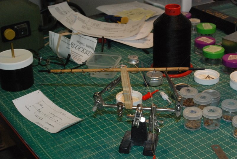
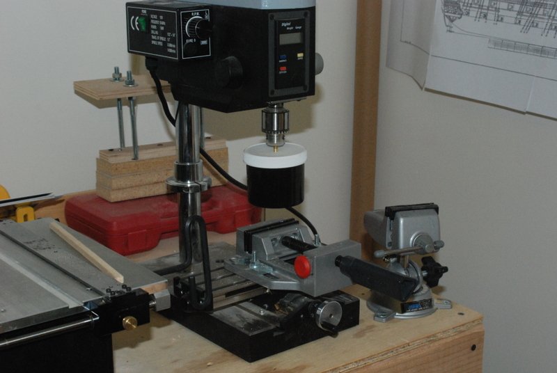
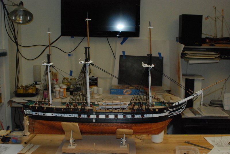
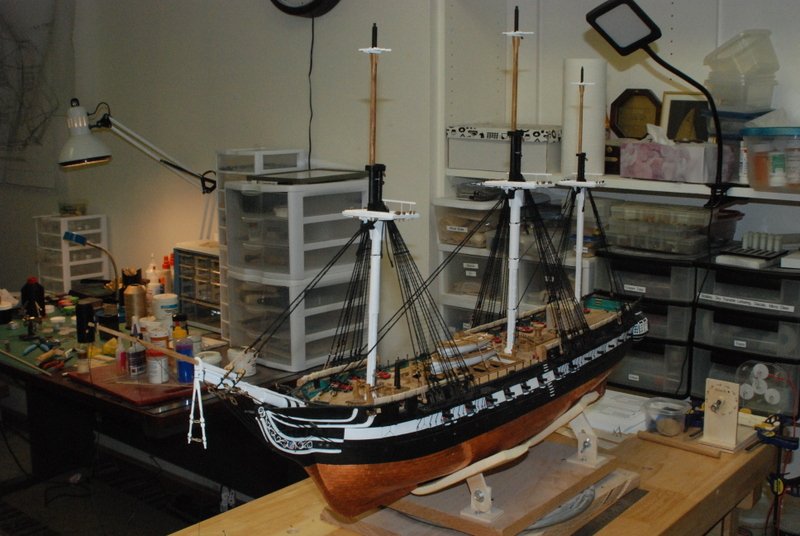
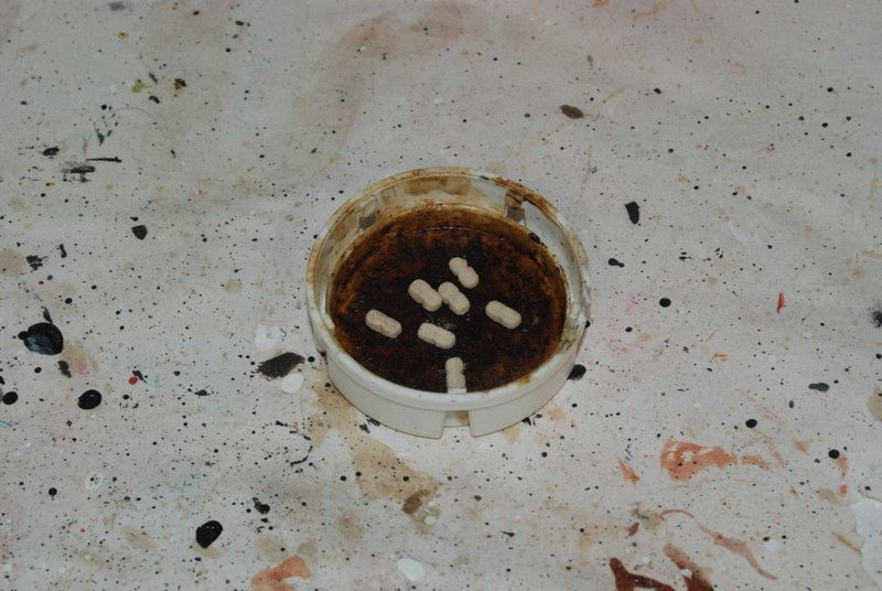
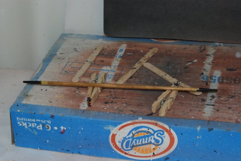
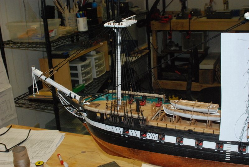
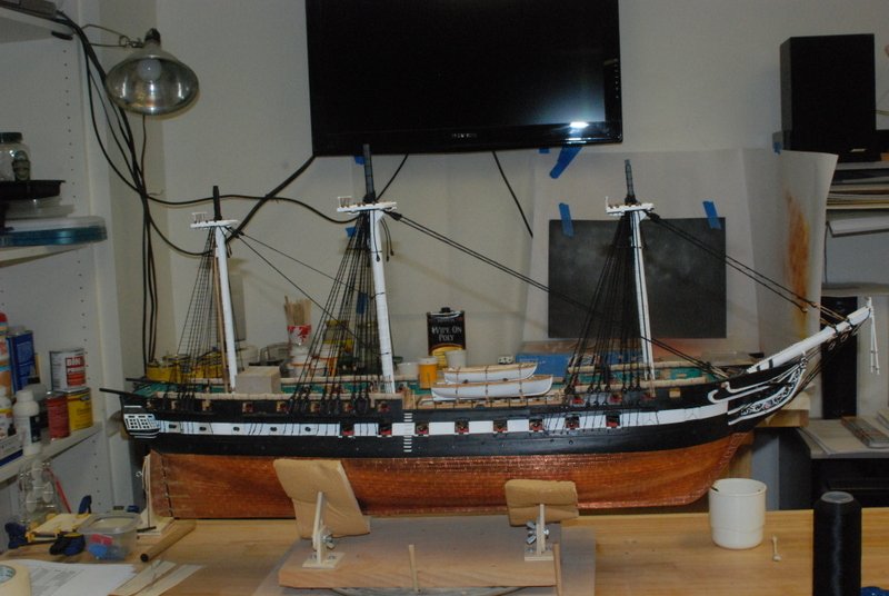
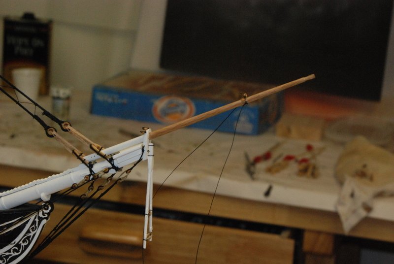
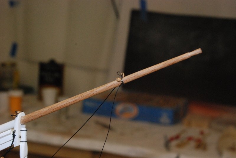
Time for an update. I have all of the topmasts installed with their associated bits & bobs on the caps and crosstrees. Many of the blocks will be installed with hooks, but I have stropped them and installed the eyebolts for them. Some blocks are installed directly on eyebolts. In order to continue the bowsprit rigging on the jibboom, I need the sprit sail yard. I made it on the lathe from some round dowel, since it is mostly round. Here I have stained it and am in the process of painting the yard arms black, which is the color scheme i am using for the lower yards. In order to install this spar with the footropes installed, I need to remove the lashing on the third bobstay, which I installed a while ago. Not a big deal, but one of those mistakes that I should have anticipated. I also need to install the sling holding this yard to the bowsprit while installing the yard, as it has seizings on both sides of the bowsprit. The other task I have been doing is getting all of the blocks ready for the rigging. I am using the kit supplied blocks and I thought I would show how I am cleaning them up. I start by using a small file to knock back the corners of the squarish blocks, so they are more oval. I do this in two dimensions so the edges are rounded too. Here you can see the kit supplied blocks on the right and a filed block to the left of those and in the cap. I then turn these in the block tumbler shown below. I got this from Model Expo a few years ago and beefed up the insides a bit. I run the tumbler on the dress press at about 1200 RPM or 1/4 of the speed of the press, for a few minutes. While it is running, I hold the container up so there is good contact of the sandpaper inside with the bottom of the cup. Here is what the blocks look like out of the tumbler. There is quite a bit of sawdust inside and I am always surprised that there is anything left in the cup when I open it. I just picture everything inside turning to dust. I then stain the blocks using a dedicated cap using an old paint brush. I dip the brush in stain and roll the brush around within the blocks until they are covered on all sides. Here the blocks are the left have been stained and the blocks on the right are waiting for their turn. I also needed some sister blocks for the lower yard rigging, so I made some out of 1/4 by 1/8 inch basswood. Unfortunately I did not take pictures during the process, but I will describe it. I first drilled two lines of evenly spaced holes along the length of the wood strip, then used a round file to make grooves on each side between the line of holes for the top and bottom sheaves. I sanded the edges round, then cut the individual blocks from the wood strip. I cut these so they were fairly thick, then thinned them down on the disk sander. I also used a file and sandpaper to get the final shape on each one. I used a triangular file to make the stropping groove around each one, then tumbled and stained them like I did the other blocks. Here they are just before staining. Next up is to finish and install the sprit sail yard, then on to the futtock shrouds on the other masts.
- 1,354 replies
-
- 9
-
-
- constitution
- model shipways
- (and 1 more)
-
Very nice , David. You should be very proud of her.
- 117 replies
-
- 1
-
-
- constitution
- model shipways
- (and 1 more)
-
Thanks Rob, and for the likes. I have finished the ratlines on both sides of the lower shrouds and tied on the futtock staves. It is nice getting to this point in the build. I next did some more bowsprit rigging. I had made this jibboom traveller a few months ago, modeling it off what Chuck made for his Syren build. Before installing it, I seized two small blocks to it for the jib downhaul and tackle, and the two inner fixed guy lines. I then slid the jibboom through the bowsprit cap from the back, and slipped the traveller onto the jibboom. The jibboom was not sitting flat into the saddle, so I filed out the hole in the cap a bit until it did, then glued it to the saddle. I had made this bracket to fit over the saddle before, so I just glued it in place. I seized eyes into the ends of two lines for the fixed inner guys and added them to the end of the jibboom, and seized two bullseyes with loops for the martingale stays and slipped them over the end of the jibboom. This is as much as I can do on the bowsprit until I make and install the bowsprit yard. Before that I am going to work on the mast caps and install the topmasts.
- 1,354 replies
-
- 7
-
-
- constitution
- model shipways
- (and 1 more)
-
Miniature Hand Tools
usedtosail replied to Julie Mo's topic in Modeling tools and Workshop Equipment
Not too much yet, since I am deep into the rigging phase of the Connie, but I did use them a bit when I was making the mast tops. -
Another beauty Chuck. as always, your build logs/practicums are chock full of useful information, tips, and techniques. Thank you for that.
- 1,051 replies
-
- 5
-
-
- cheerful
- Syren Ship Model Company
- (and 1 more)
-
Nice work on the bowsprit rigging, Ken. As soon as I finish these !*#@! ratlines (should be tonight), I'll be working some of this bowsprit rigging also.
-
Miniature Hand Tools
usedtosail replied to Julie Mo's topic in Modeling tools and Workshop Equipment
Sigh, I bought the Glardon-Vallorbe fiffler set a few months ago. I'll just have to augment with other files as you describe as I need them. -
Miniature Hand Tools
usedtosail replied to Julie Mo's topic in Modeling tools and Workshop Equipment
I hear you Jeremy. Every time he posts my wish list gets longer and my wallet gets thinner. -
Nice looking deck you have there.
-
Looking good Mike. I like your use of rubber bands (or elastics as we say up here in New England) and clamps to hold the wales. All of the false quarter galleries I have seen are badges that fit over the planking, but I am not sure if there would be an opening into the hull under them in the real ships.
-
That book is a great idea and looks fabulous. It is missing your name on the cover though.
- 366 replies
-
- 2
-
-
- pegasus
- victory models
- (and 2 more)
-
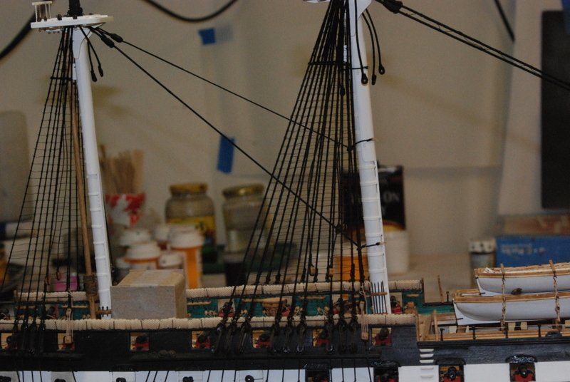
Sorry Al, its Charlestown, like the movie The Town that was filmed there. Great chase scene in that movie on those narrow streets. Charleston is one (or more) of those cities down south somewhere. I finished the ratlines on the port side, all three masts, and have tied on all the ratlines on the starboard main shrouds. I'll fix those knots tonight. No pictures as its hard to see the ratlines without anything behind them. I am using thin sewing thread for the ratlines, which helps keep the end shrouds from being pulled out of straight and the knots not too big.
- 1,354 replies
-
- 2
-
-
- constitution
- model shipways
- (and 1 more)
-
Glad you got to Fenway Pahk. The game was on at the graduation party I went to on Saturday. It looked like a good one.
- 742 replies
-
- 4
-
-
- constitution
- frigate
- (and 1 more)
-
Here we are. Had a great visit too. You'll have to come back when she is all up and rigged again.

- 742 replies
-
- 8
-
-
- constitution
- frigate
- (and 1 more)
-
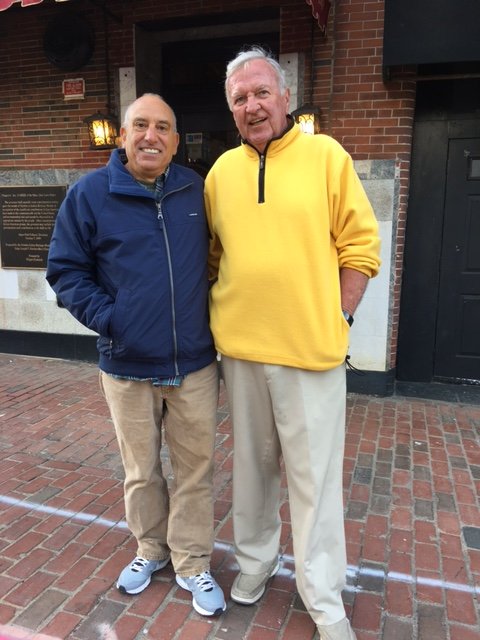
Thanks Michael, Vossie, and Al. I don't know about doing a guide. Maybe things not to do more than how to do it right the first time, ha ha. I met up with Sawdust Dave and his son Mike yesterday in Charlestown. We had a great visit over a couple of beers and they headed off to the North End for some good Italian food. Dave is the handsome guy on the right.
- 1,354 replies
-
- 5
-
-
- constitution
- model shipways
- (and 1 more)
-
Sounds like a good plan.
-
Sounds great Anthony. Will you have a separate build log for it?