.JPG.ca33079f5815b861e67b9c2cccd37982.JPG)

Blue Ensign
-
Posts
4,567 -
Joined
-
Last visited
Content Type
Profiles
Forums
Gallery
Events
Everything posted by Blue Ensign
-
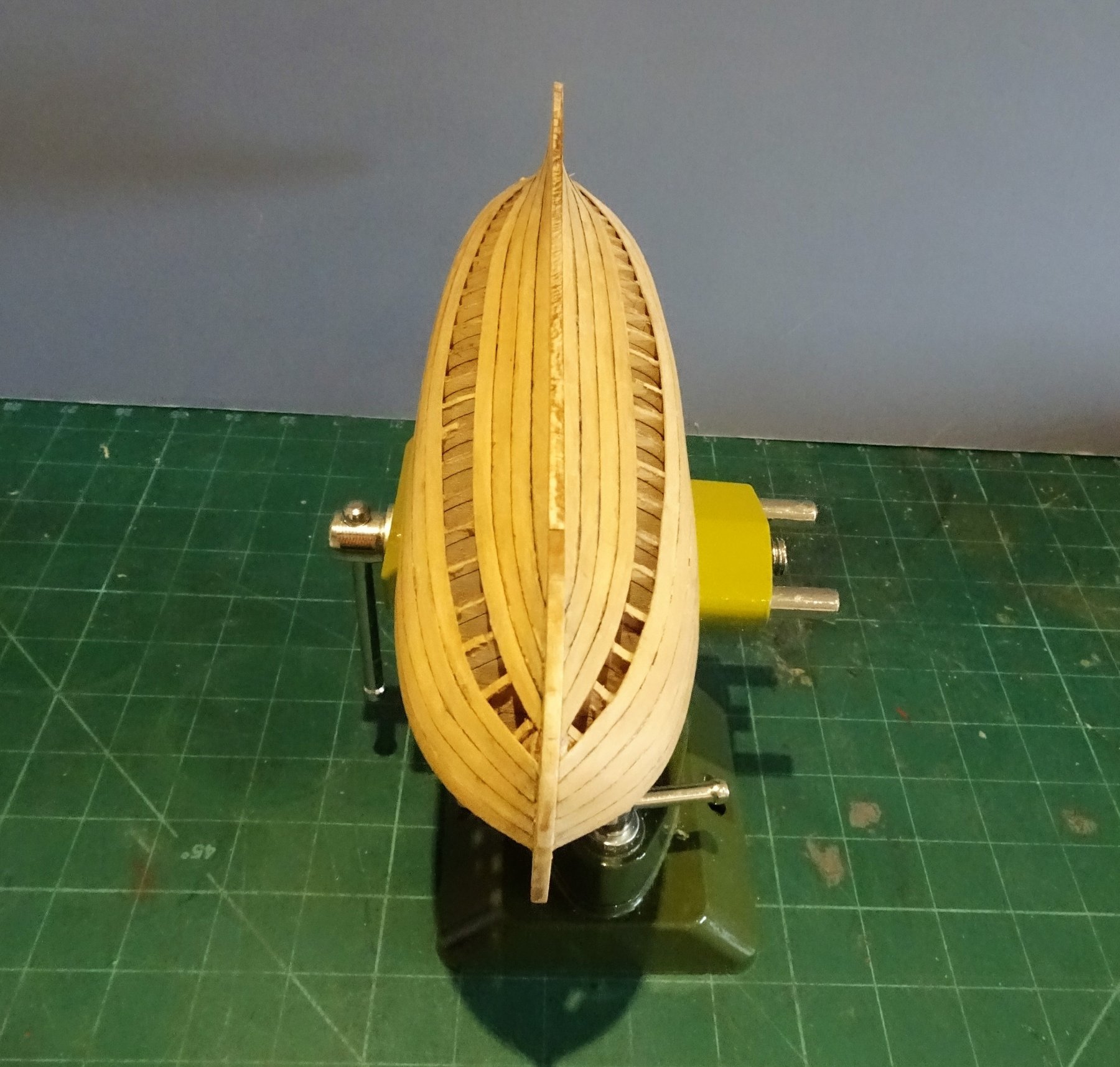
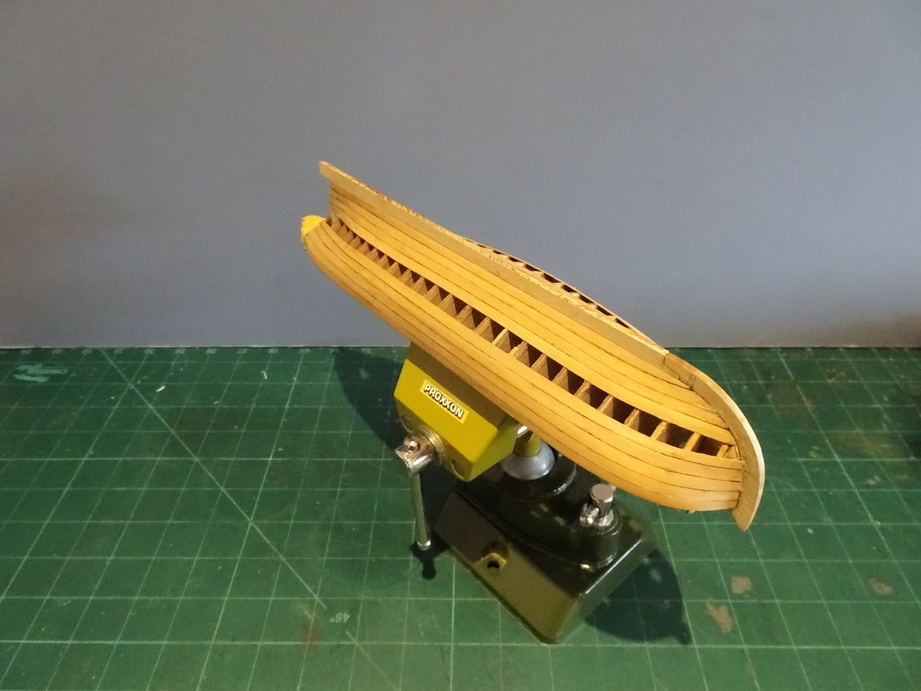
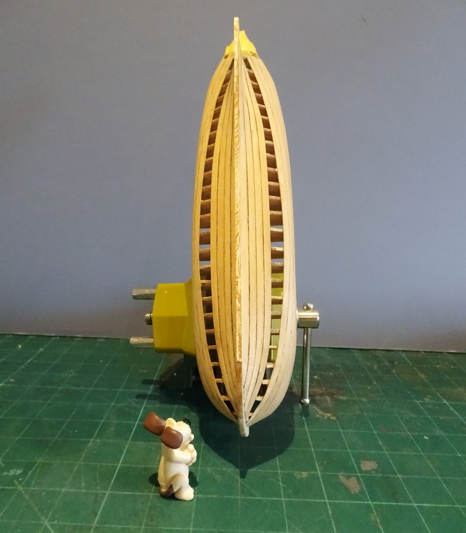
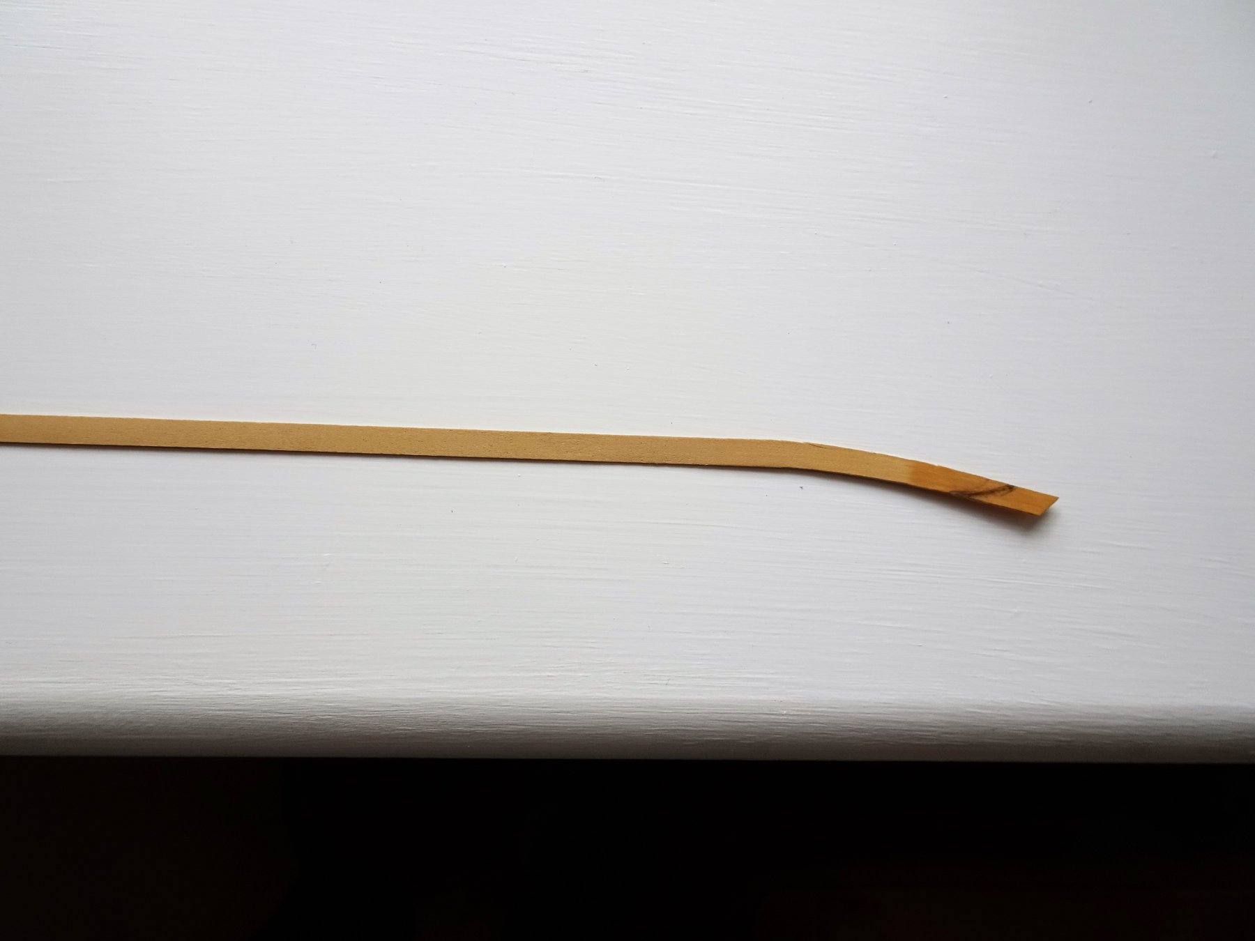
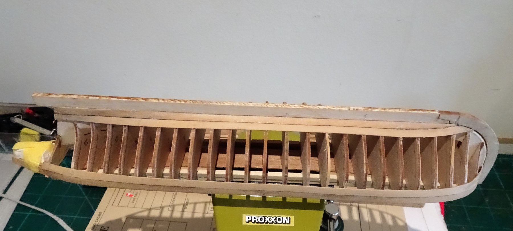
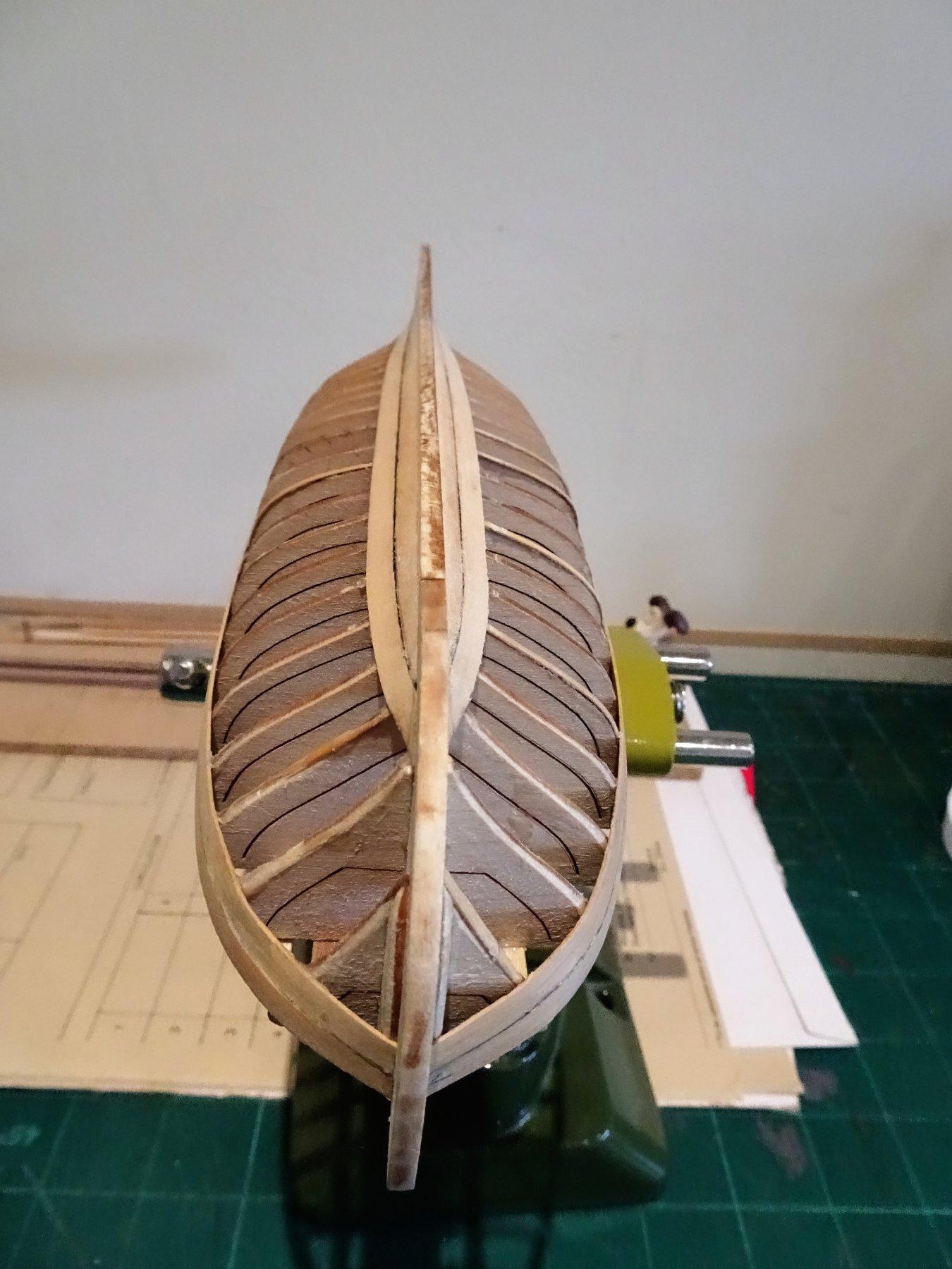
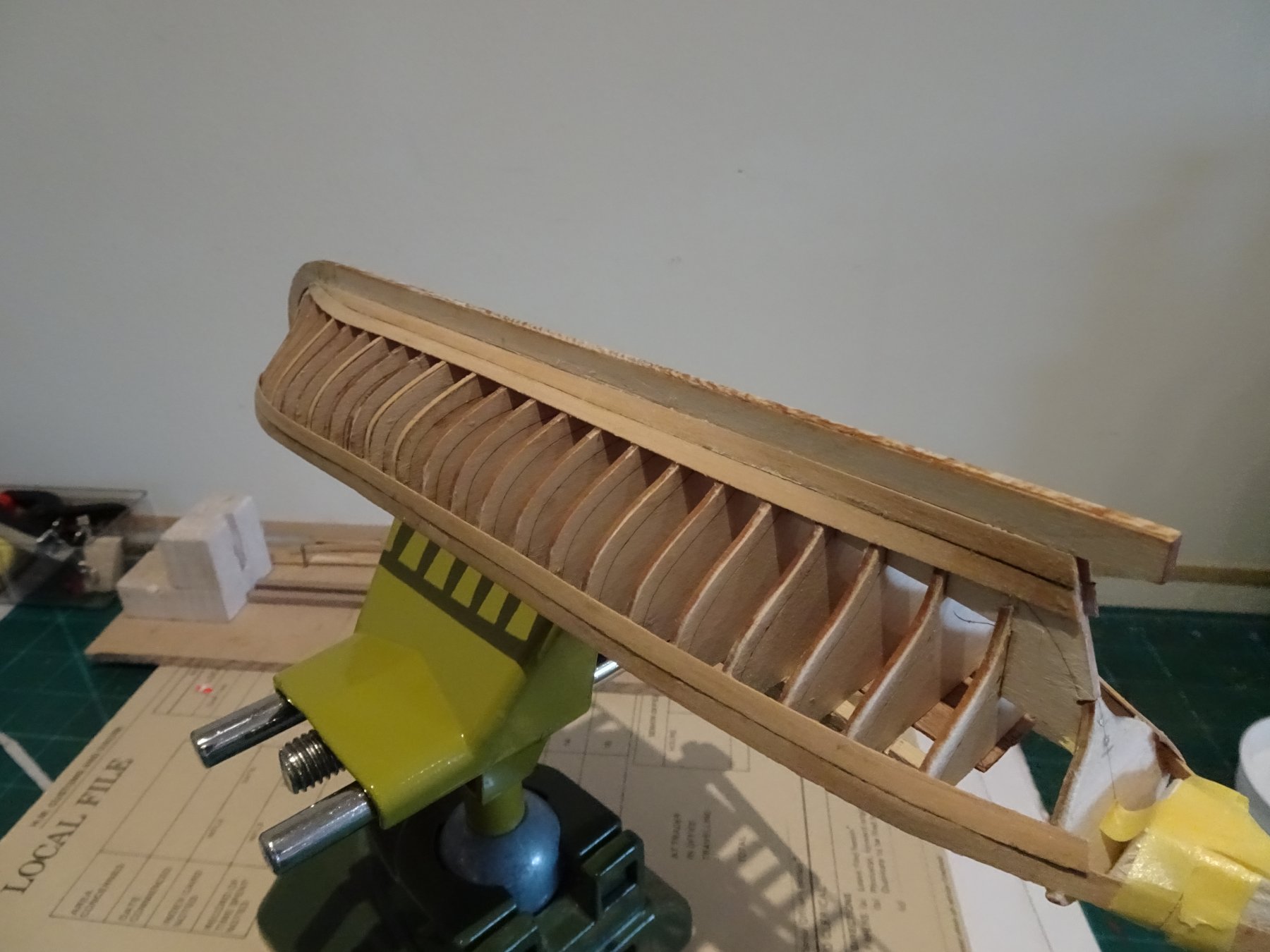
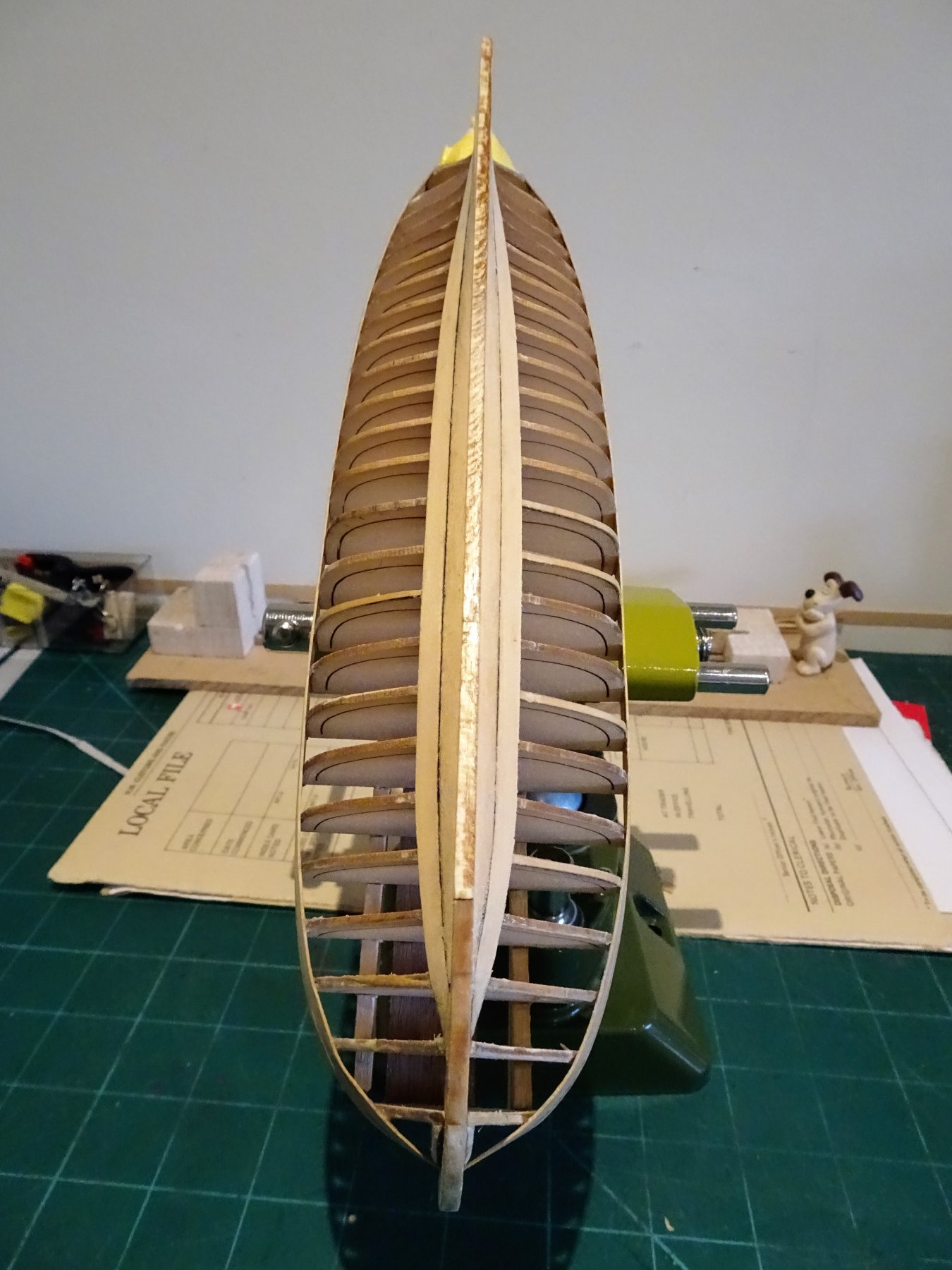
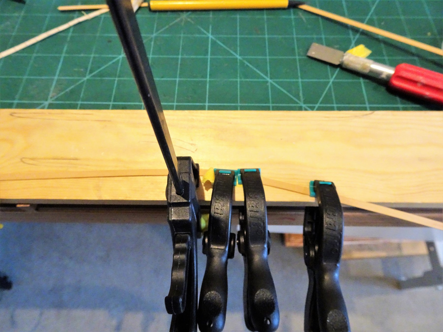
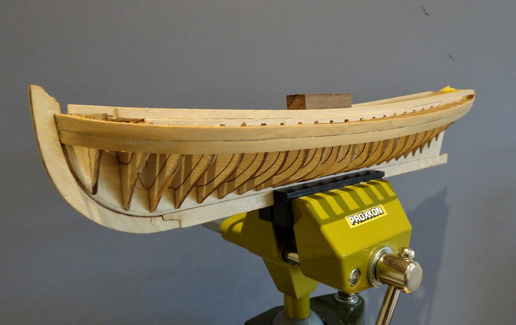
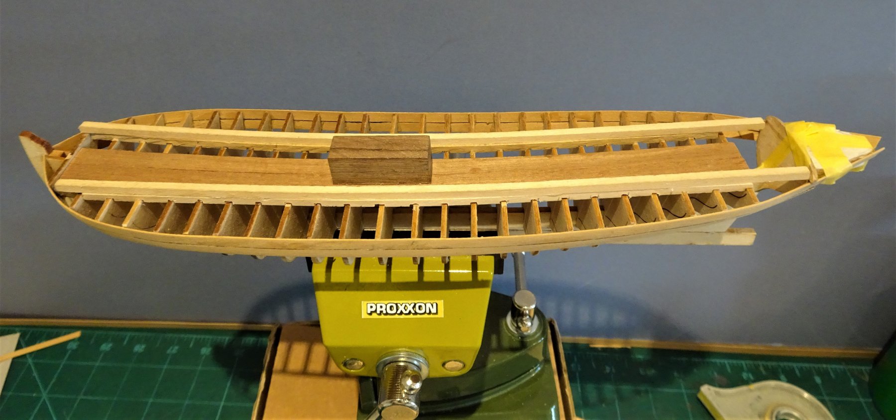
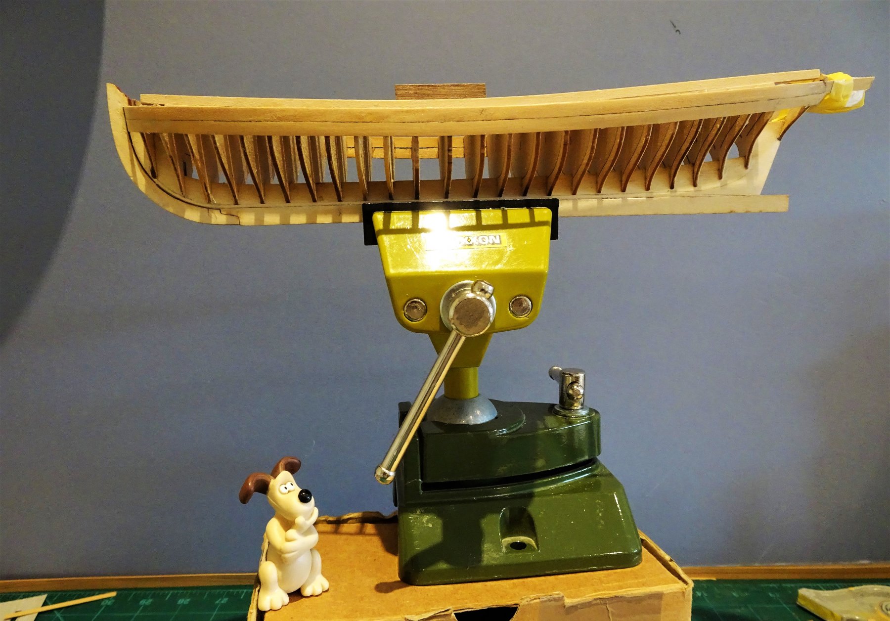
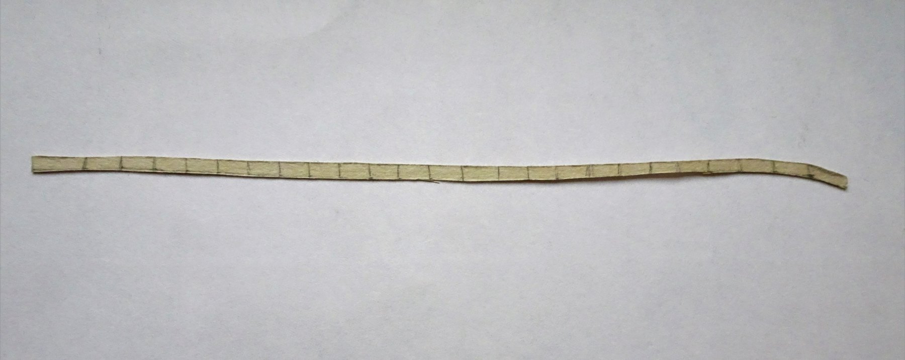
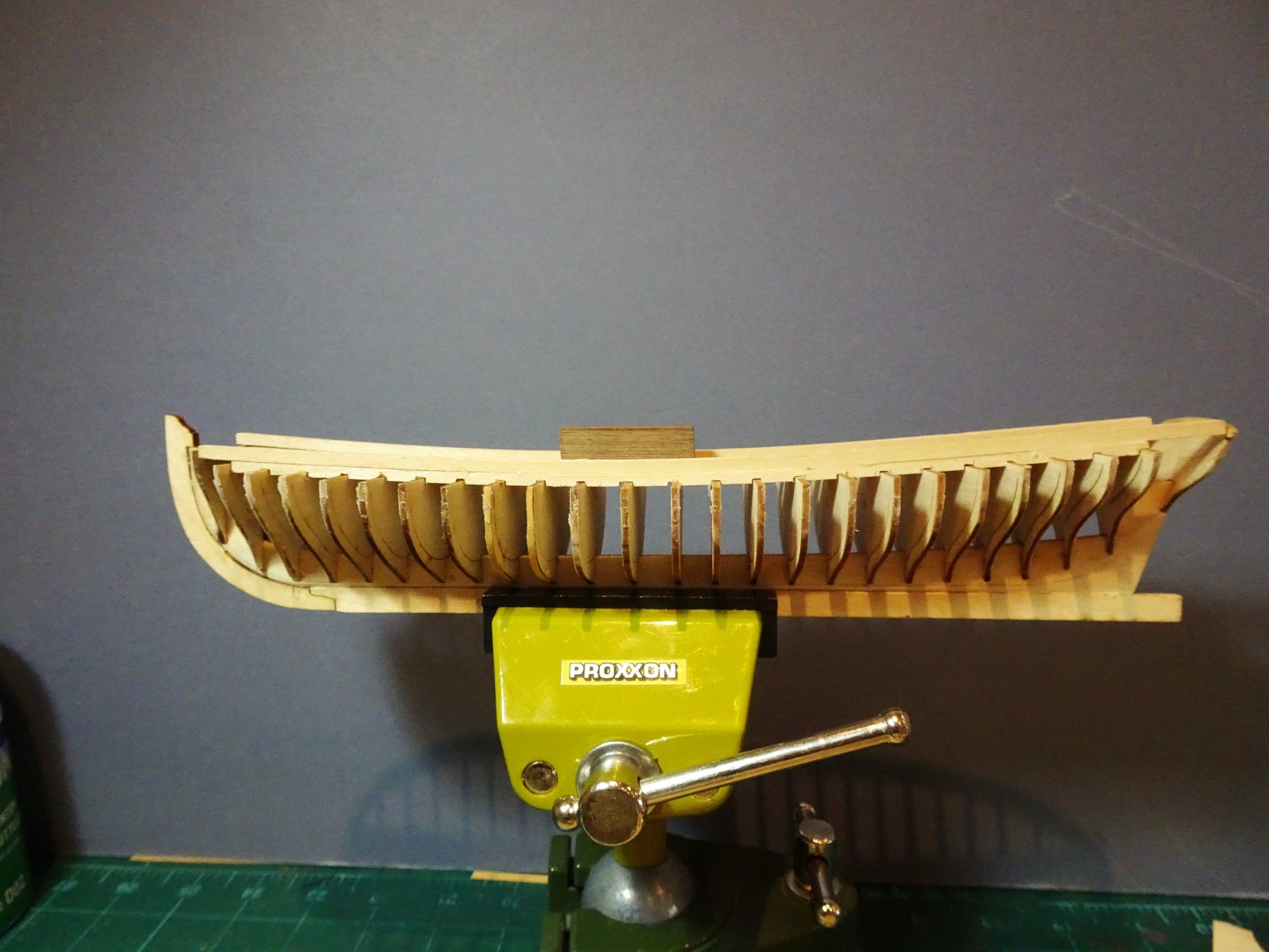
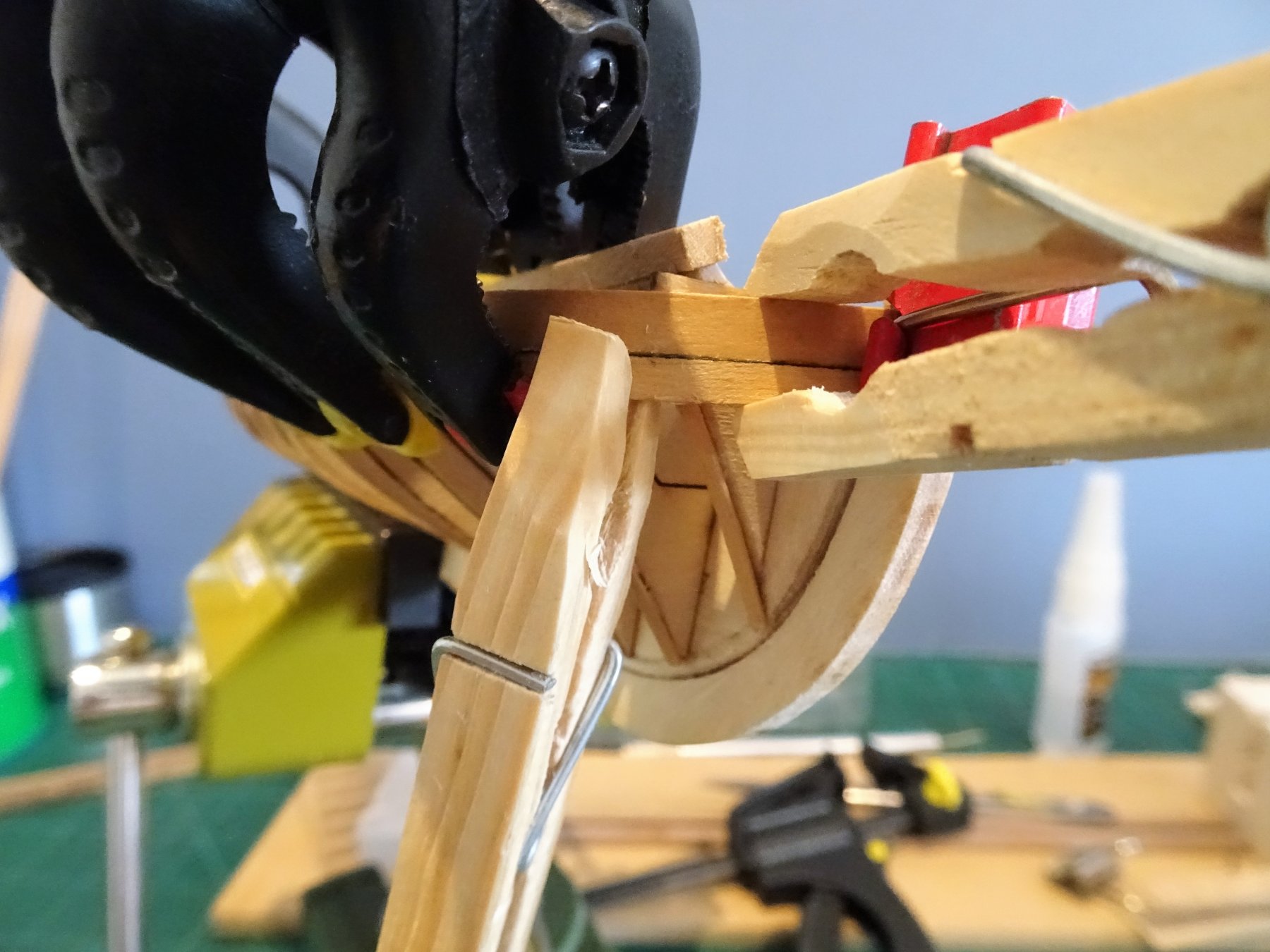
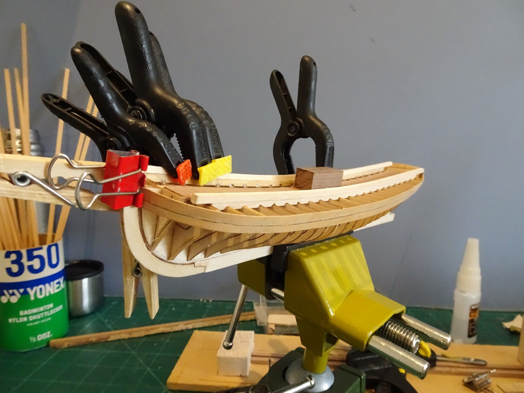
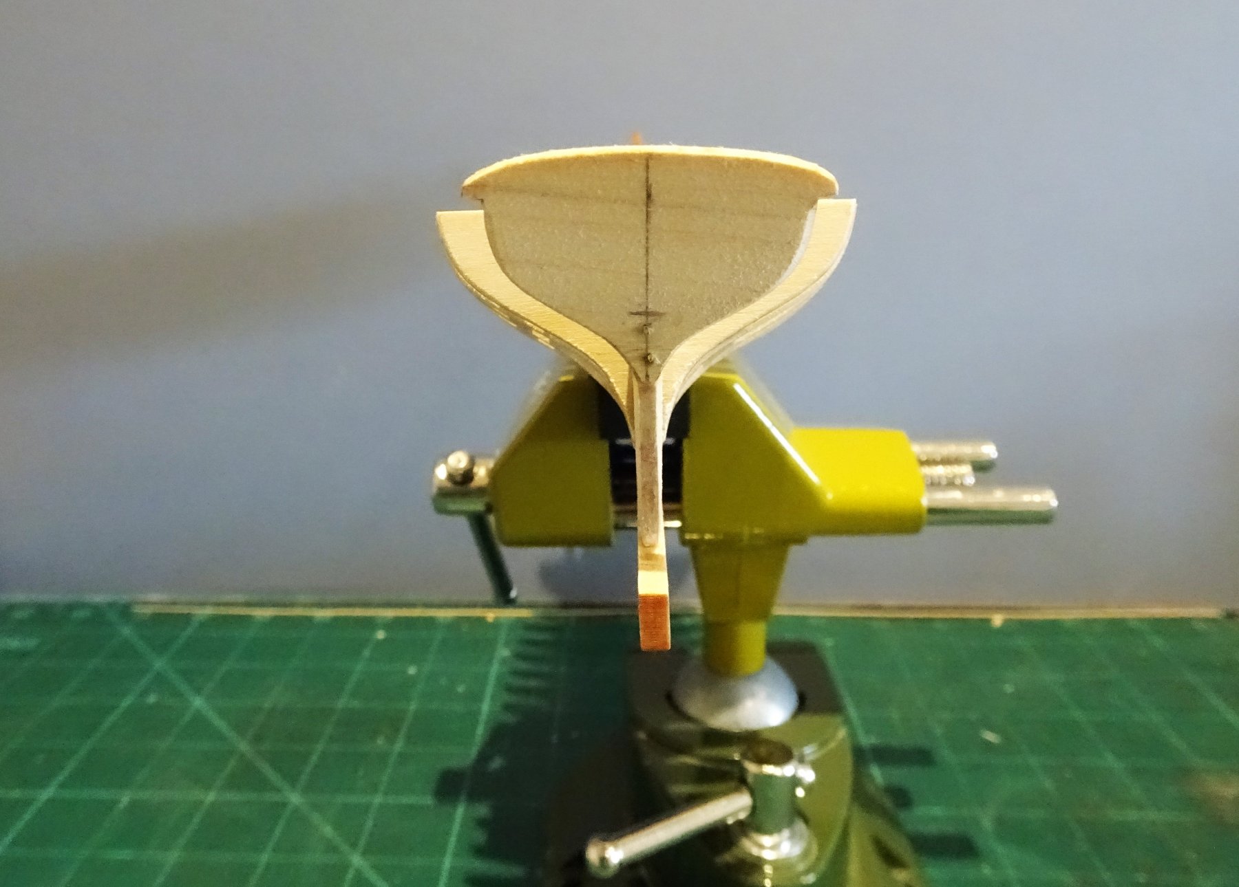
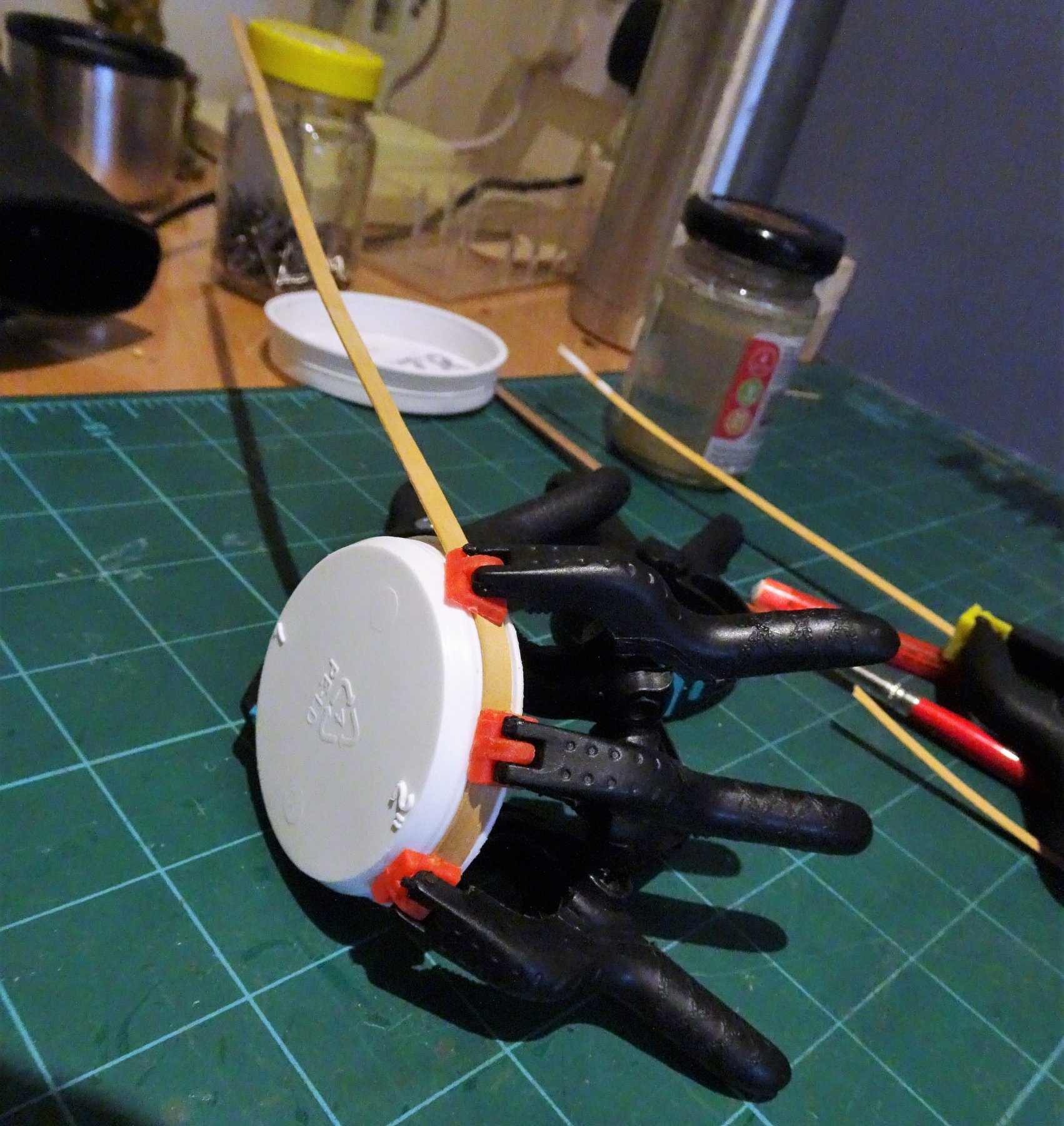
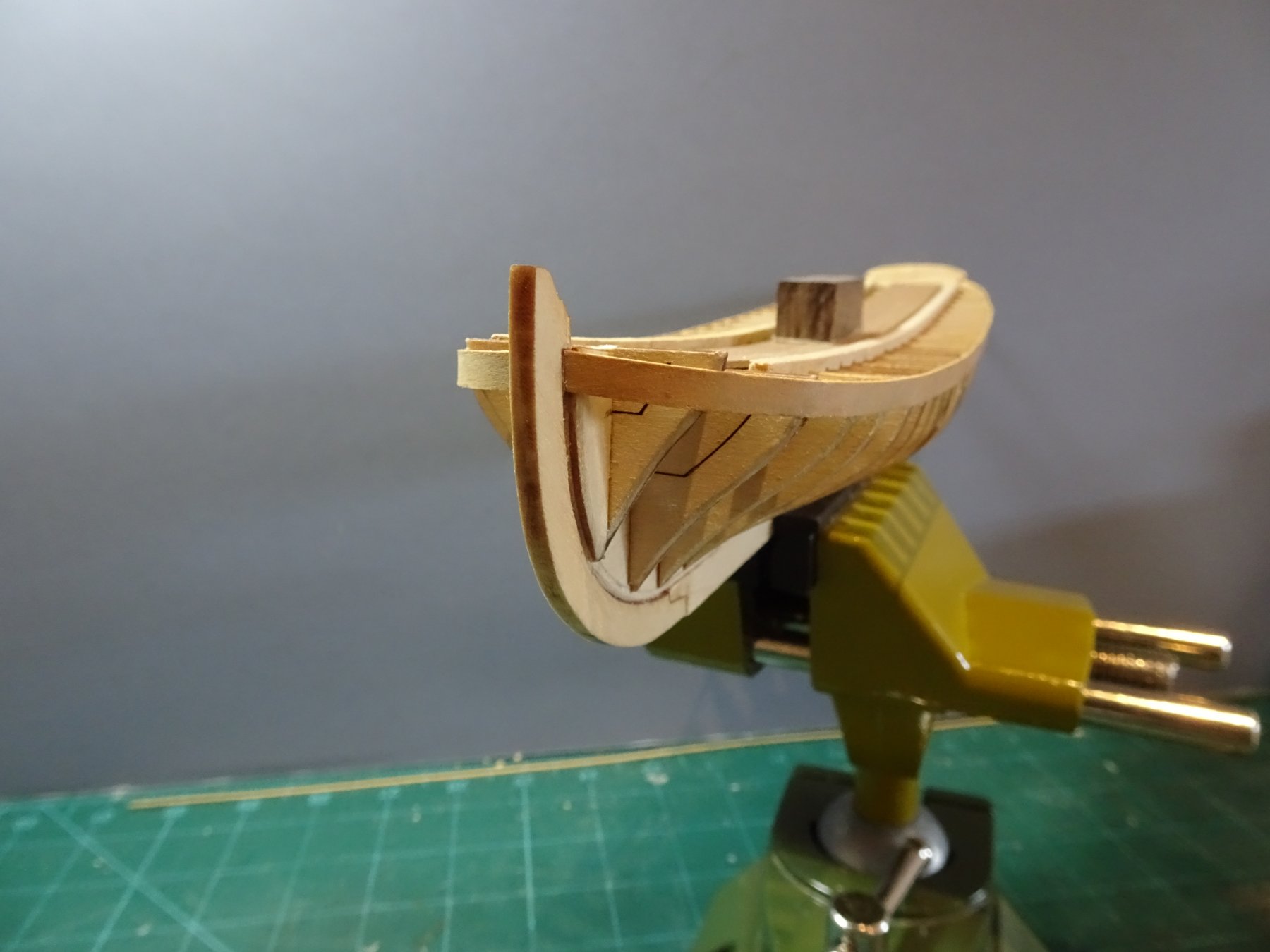
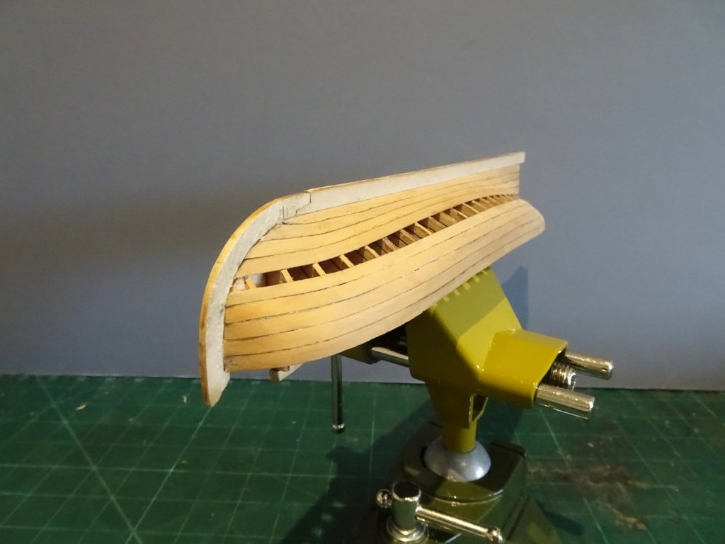
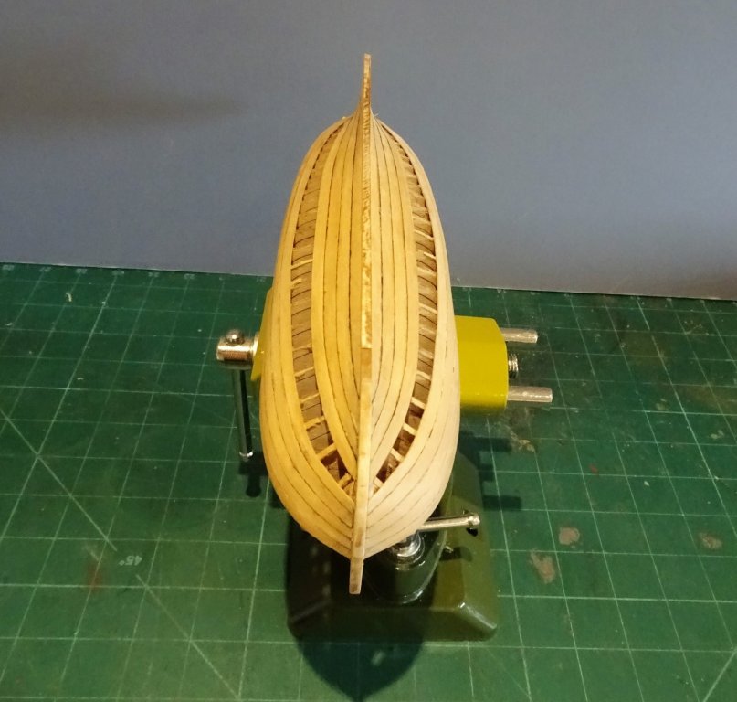
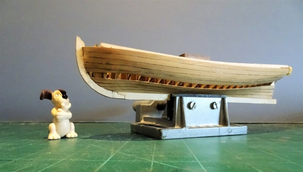
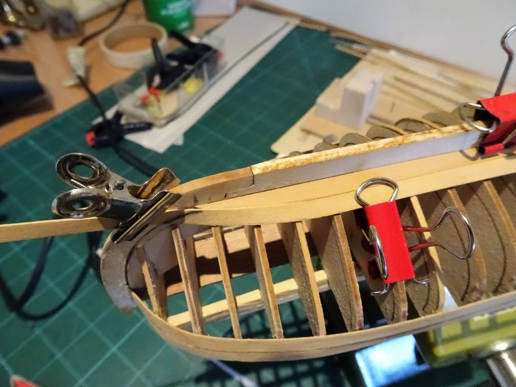
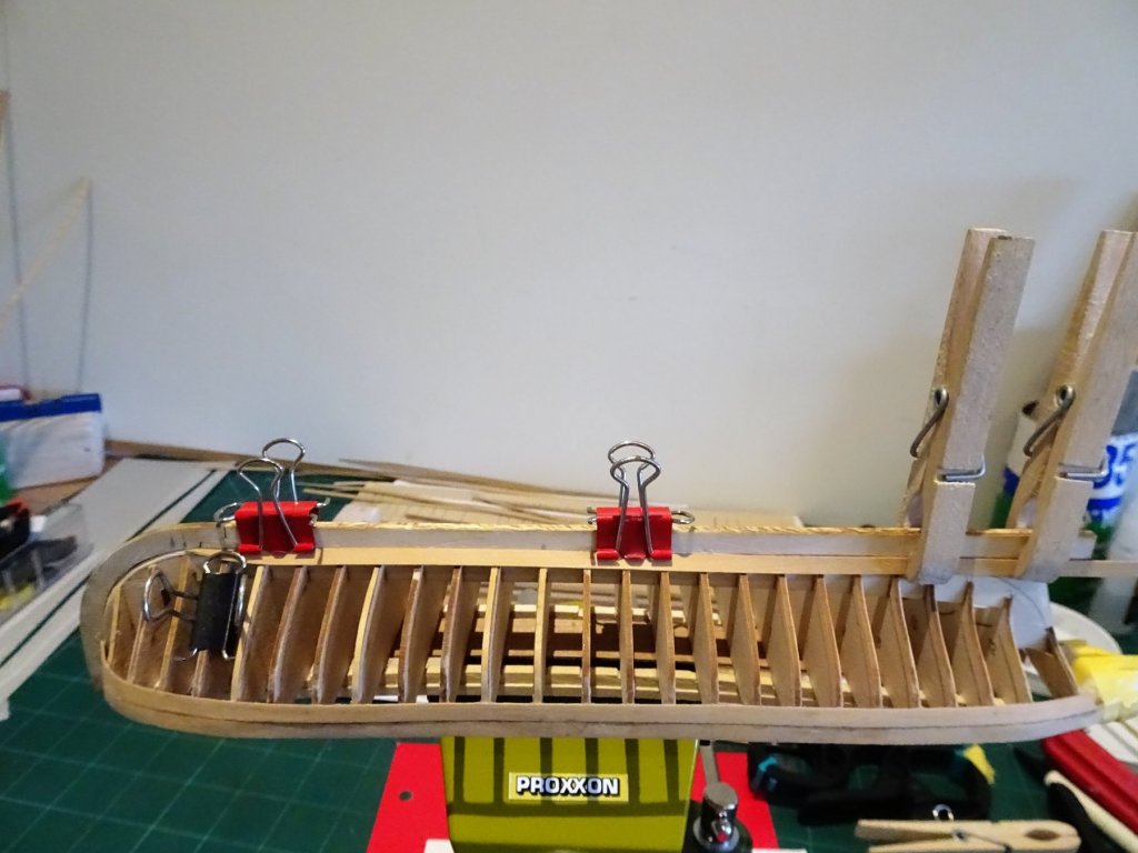
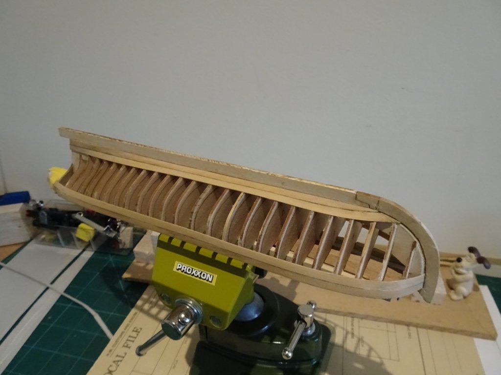
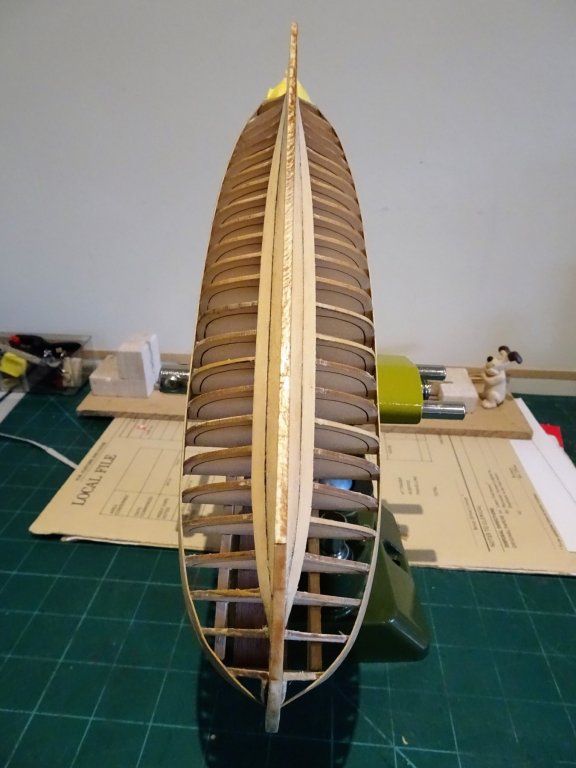
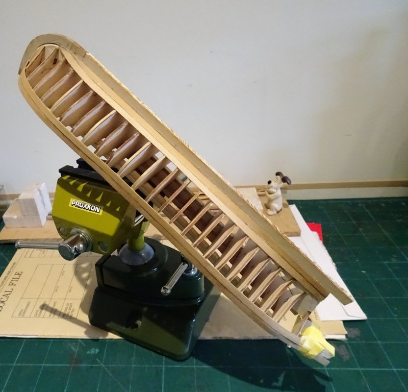
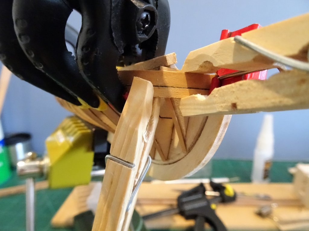
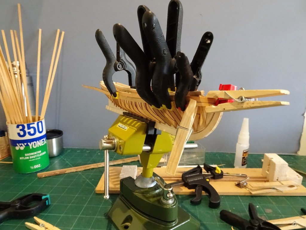
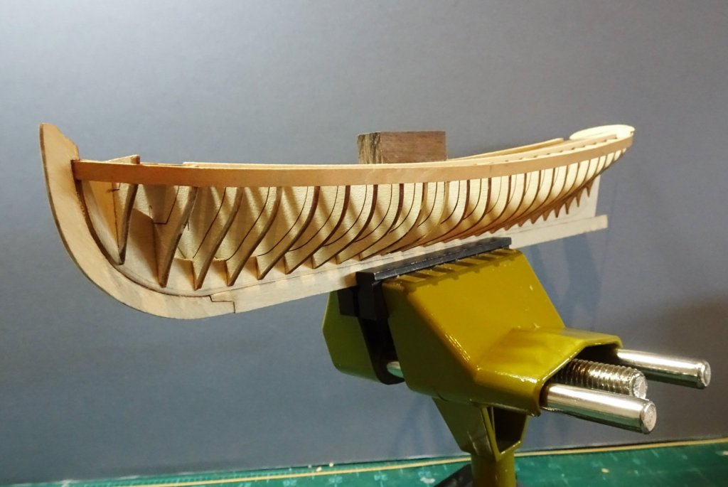
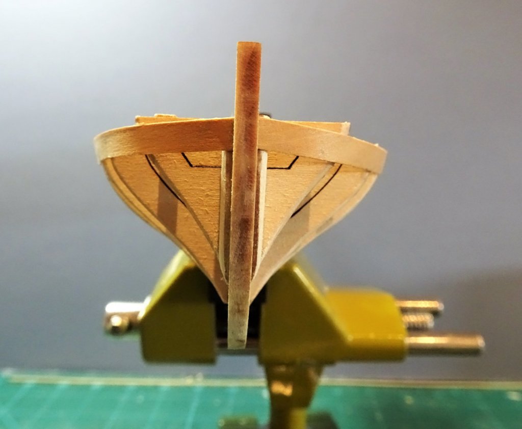
 Oh dear it seems like one step forward and three steps back with this build. Having fitted four strakes each side along the bottom, something didn't look right, there was a creeping mismatch at the fore end between Port and Starboard so the strakes on the starboard side including the garboard plank were taken off and re-done. 8873 Balance restored. Using pva allows this re-work without too much effort and importantly without damaging the frames. A slight wetting and easing with a scalpel blade and off they pop. Certainly would not have been so easy had I used c.a. The first four strakes from the top sheerline are untapered. 8872 ...but the fifth required a degree of taper both forward and aft to allow for the fit of the remaining strakes. There was also edge bending required. 8874 8870 8879 Something amiss Gromit? 8880 What's that you say Gromit, is there enough room for two remaining strakes? We'll see Gromit, we'll see. One thing I wish I had done with this build at the outset was to replace the Lime/Basswood keel and stem with Boxwood. It really is a poor wood for this purpose where clean and sharp edges are desirable. It will take careful sanding to remove the scuffs and marks, followed by application of sanding sealer to preserve the surface. Am I happy with progress thus far, the jury is still out on that one, finding this a very tricky build; I'll see how I feel once the planking and a sanding finish has been applied. B.E.
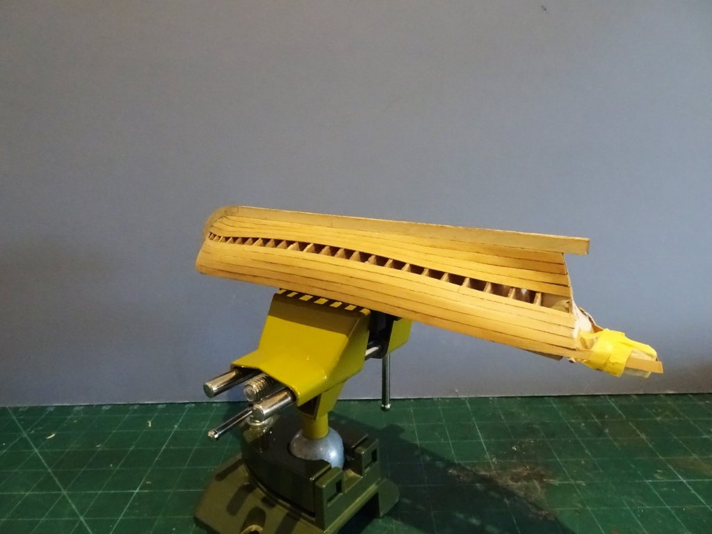


- 156 replies
-
- 19
-

-
- pinnace
- model shipways
- (and 1 more)
-
Nice sharp work on the Gangboards and brackets Martin, not too sure about a support post for the Gangway, - aesthetics over practicality, hmmn, I'll await developments. I believe I got around the problem by having one bracket that supported both the Gangway end and the gangplanks end that finished beneath it. I wouldn't sweat it tho' once everything else is in place, you'll be hard placed to see anything of the fine detail. B.E.
- 467 replies
-
- 1
-
-
- fly
- victory models
- (and 1 more)
-
Looking all very shipshape Steve, mine's starting to look a little shop soiled now Do you intend to fit a jig so that you can work on her inverted? B.E.
- 190 replies
-
- 3
-
-
- pinnace
- model shipways
- (and 1 more)
-
Cheers Guys, 😊 Hi Christan, unfortunately this is single planking with much fining down of the frames internally once the planking is completed. Not much room to hide things on this build. Surely does concentrate the mind knowing that you don't have a second bite of the cherry with second planking, or a third with coppering. 😬 B.E.
- 156 replies
-
- 6
-
-
- pinnace
- model shipways
- (and 1 more)
-
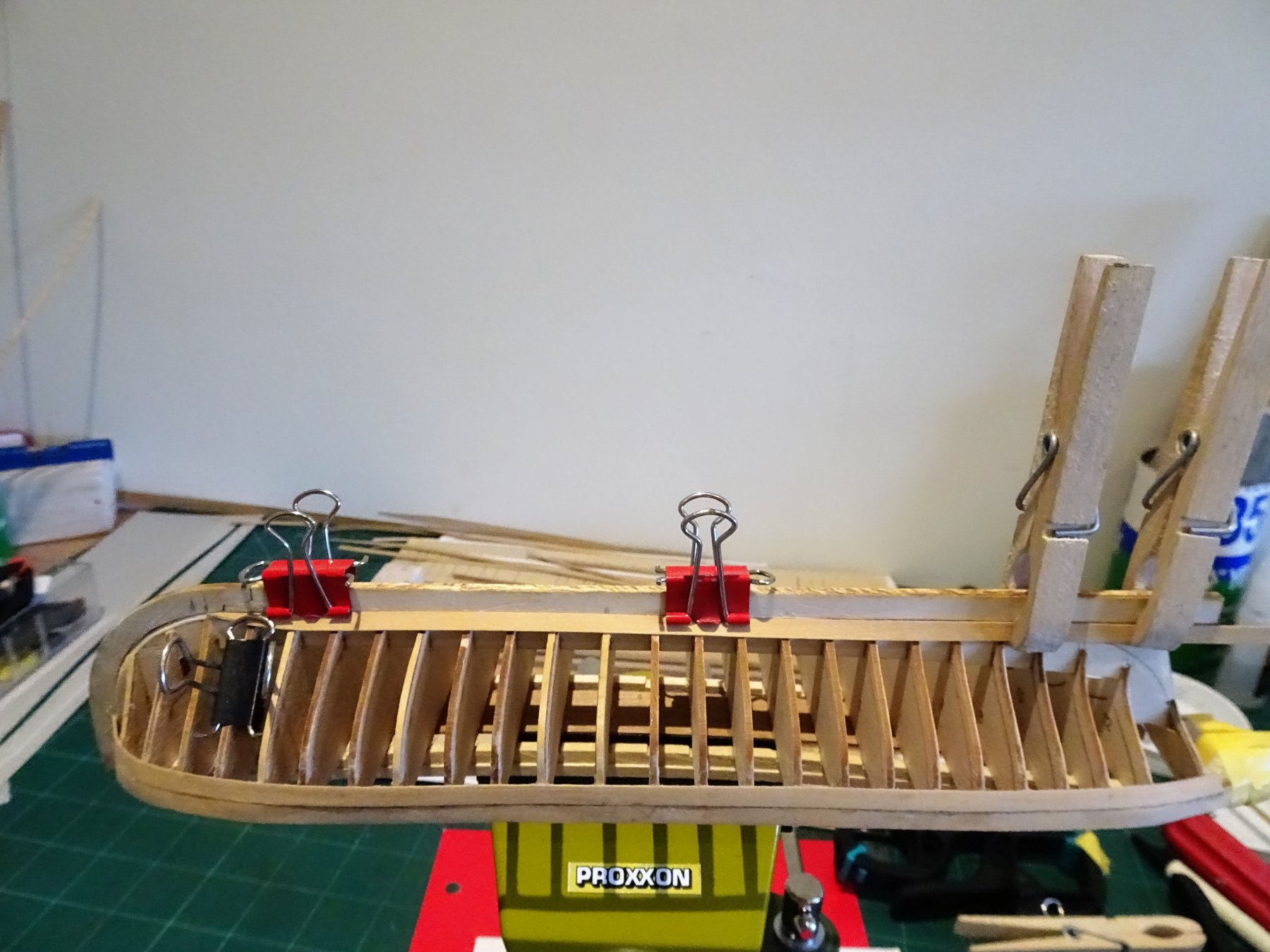
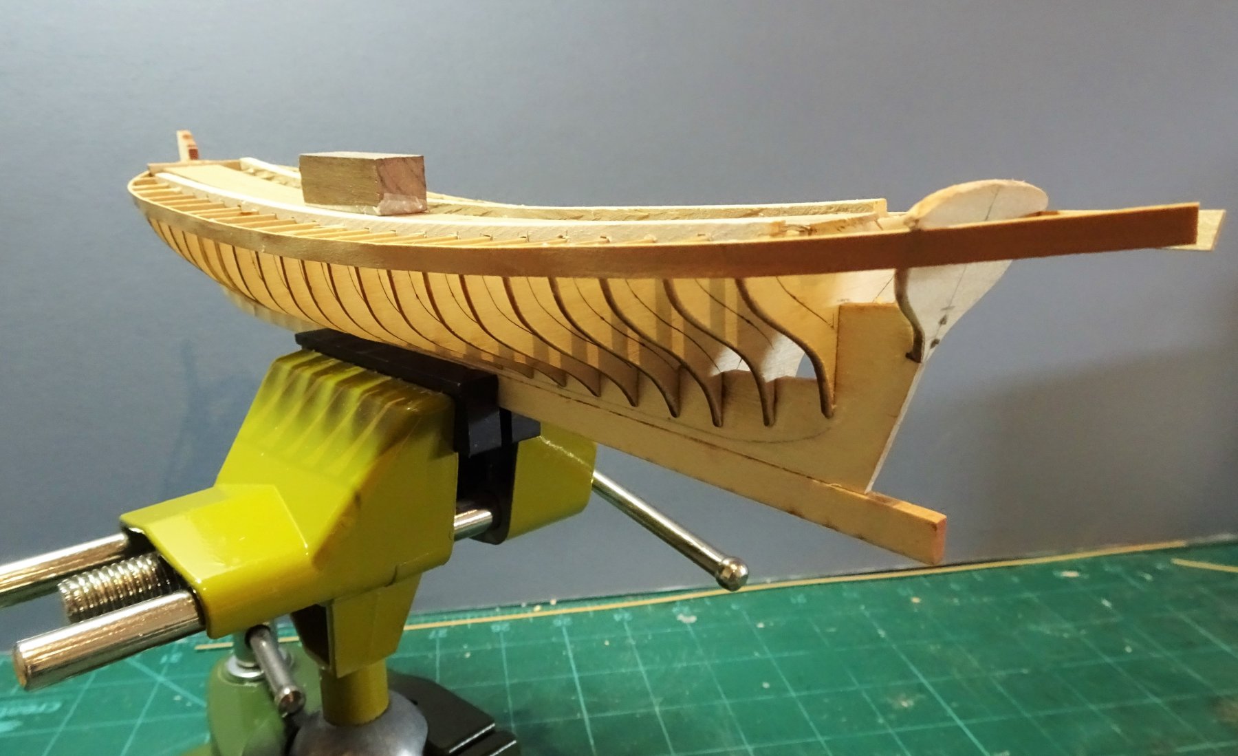
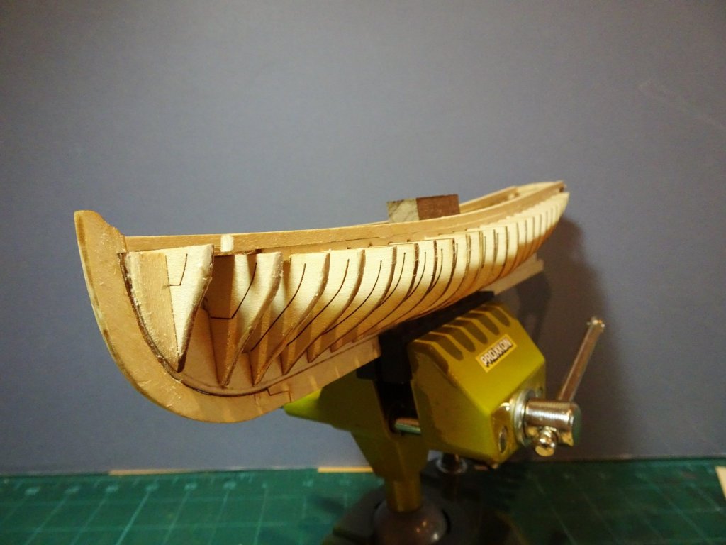
The Garboard planks are now fitted. 8515 8516 For these I used straight strip shaped by reference to how Chuck's build appeared to look in his photo's with the end just extending beyond the scarf joint in the keel. This has to be done in conjunction with the one above it, before it can be glued into place. 8513 Working the strake above the Garboard. A fair bit of fiddling about here. 8518 There is a severe curve at the bow end to go around the Garboard and fit into the rabbet at the stem. This was formed from around the centre of a much longer piece of strip, to get the necessary curve. 8526 Once I was happy the two planks would match, the Garboard was glued into place. 8533 Port side bottom strakes fitted. The second strake is also full size without any tapering. I think I've achieved the objective of keeping the second plank from creeping upwards at the stem. 8534 8529 Only wet and dry heat was used to form the shapes. 8532 The stern section of the strakes also untapered was problem free in fitting. 8537 I now need to work out the required tapers for the intervening planks. I will then work from both top and bottom. B.E.


- 156 replies
-
- 19
-
-
- pinnace
- model shipways
- (and 1 more)
-
Great progress Christian, she is looking splendid. 😊 B.E.
-
Thanks Jason, I'm back from Dorsetshire now and ready to do battle with the Garboard plank and the one above it. Ideally I want to get these two fitted and then work out the plank tapers for the ones in between working both up and down to infill. B.E.
- 156 replies
-
- 6
-
-
- pinnace
- model shipways
- (and 1 more)
-
Hi Michael, I'm not referring to Footropes or horses as slung below the yards, but the complicated crowsfeet arrangements fitted to many stays on ships of the 17th century. The crowsfeet that are fitted to the tops of 18th century ships were the last remaining vestige of the use of crowsfeet which died out towards the start of the 19th century. The sort of attachments shown in your last photo above would I believe be classed as crowsfeet, but a prime example of their use in 17c ships would be the Spritsail Topmast backstays, certainly on English and Dutch ships, where very fancy set ups were the order of the day. The Martnets (or Leechlines) were also of a similar form, and may benefit from some stiffening assistance to get them to look right. Cheers, B.E.
-
The problem with retro fitting the gun barrels, except perhaps for the 'hidden' guns is that how do you then get to fit the trunnion cap squares, tricky little beasts to fit at the best of times, let alone the keys and chains. .... but if perhaps you're not over bothered by such fripperies then the issue doesn't arise 😉 B.E.
- 467 replies
-
- 1
-
-
- fly
- victory models
- (and 1 more)
-
Love the latest shots Michael, she really is a beauty. Re tensioning the plethora of Crowsfeet on ships of that era; to get them to look right without pulling other lines out of true you may need to resort to stiffening them insitu using diluted wallpaper paste or similar. It's a method I've used with some success in the past, once attached, the Crowsfeet are put under proper tension using a temporary line and stiffened until they stand on their own. The procedure can be repeated until the desired effect is obtained. B.E.
-
Like what you've done with her Mike, I'd be pleased to. Only hope I can get somewhere close with my own effort. B.E.
- 129 replies
-
- 1
-
-
- finished
- model shipways
- (and 1 more)
-
Your thought processes re the gangplanks mirror mine Martin. I couldn't get over the awkwardness of those Foc'sle ladders, and fitting the gangplanks also provided an opportunity to differentiate the model from the basic kit layout, something I am prone to. Re pinning the guns; even at this fairly short interval my memory starts to dim, but I believe I set the carriages in place on the deck, and micro drilled thro' the carriage bed into the deck. I then c.a.'d the pin into the deck, trimmed so that it would just fit up to the level of the bed. With the gun completed I just coaxed the assembly over the pin, adding a spot of c.a. before I pushed the carriage to the deck. - but epoxy sounds good too. I await with interest your next update. Regards, B.E.
- 467 replies
-
- 1
-
-
- fly
- victory models
- (and 1 more)
-
Look forward to it Steve, 😊 I've had a tentative look at the Garboard strake and the one above it, and the bend does indeed look short and severe. I'm not entirely clear how to determine the exact shape of the garboard plank at the bow end as yet and its relationship to the one above, which by all accounts should not curve upwards at the stem. B.E.
- 156 replies
-
- 3
-
-
- pinnace
- model shipways
- (and 1 more)
-
You must be one of them there Cockeney Oklahomans Martin. The first two strakes have been bent but not tapered. From now on there will be tapering involved as well as bending, but at least one strake will need spiling, and maybe others if necessary. Taking a week off now but when I return I'll re-mark the bulkheads and try to fit the garboard plank. Cheers, B.E.
- 156 replies
-
- 4
-
-
- pinnace
- model shipways
- (and 1 more)
-
Thanks Chuck, I have taken your advice, and thanks for the very useful 'Barge' pdf. So the top sheer planks are replaced. 7846 Full size strips, dry heat curved after wetting to align with the bulkhead tops. This is quite a gentle curve from around the mid point with a slightly more upward sweep aft from the centre. 7851 This time I have shaped a balsa block to temporarily protect the plank extensions for the decorative transom. That's the easy bit! The second plank below the sheer plank I have also fitted untapered, but have used the water/dry heat method to create the 'S' shape as shown below. 7822 This time I started the curve much further back in a longer length of strip. 7826 The downward curve is quite severe at the bow. 7859 So Grommit what d'ye think of it so far. hmmn not too impressed eh. Time for a break I think and a trip down to Dorsetshire. B.E.


- 156 replies
-
- 19
-
-
- pinnace
- model shipways
- (and 1 more)
-
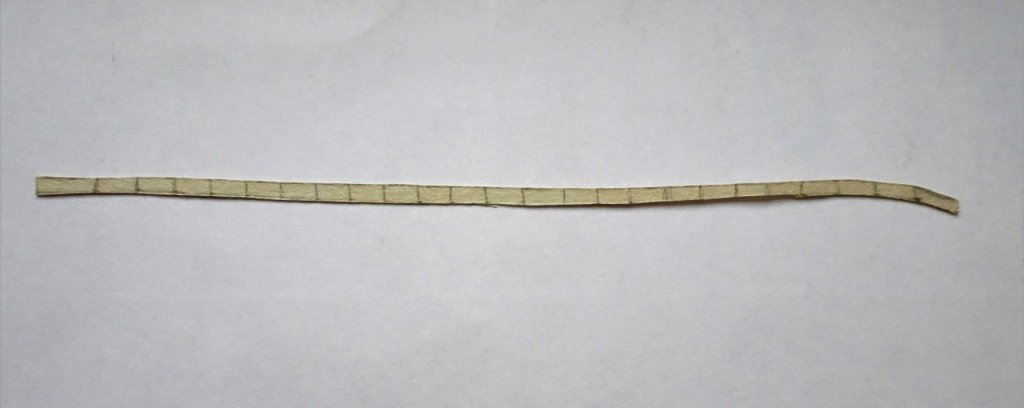
Thanks Steve, I too prefer to approach a build from both ends; once the top few planks are fitted, I like to fit the Garboard and then work up and down towards the centre. With the Pinnace particularly, the top two planks provide stability to the bulkheads. Thanks for your input Chuck, my rough spiling template indeed shows the 'S' shape. It is the short curve at the bow that has defeated me using just water and heat; aft of the first three bulkheads the treatment works fine to achieve the more gentle 'S' curve. On your original Pinnace build, where I think you just used water and heat to achieve the shape, did you have to start the short bow curve well back in a longer length of strip to give you the leverage to form the bend? Regards, B.E.
- 156 replies
-
- 4
-
-
- pinnace
- model shipways
- (and 1 more)
-
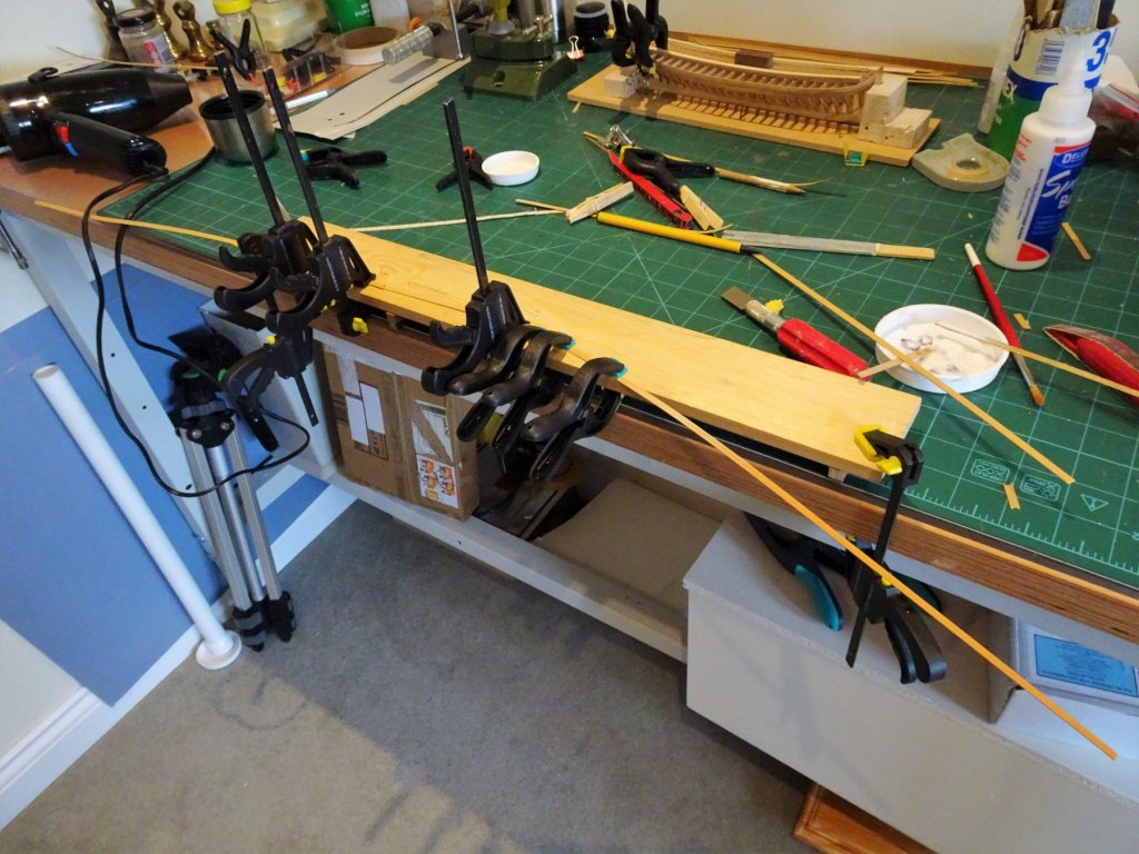
Thanks Nils and Steve. I did edge glue the planks Nils, the caulking still showed thro. There seems to be a limit to the edge bending with the Boxwood strip I am using Steve, and the downward bend over the first three bulkheads is just too severe without some buckling and within the limits of the 4mm wide strip the bottom edges just will not lie flat against the bulkhead at the lower edge. Shims would constantly have to be added with each successive strake on that basis, which is just not right. So, it's back to the drawing board. 7590 7592 After several days and much frustration I have decided to remove the first two strakes and start again. This will also allow me to re-instate the planking to take the decorative second transom which I snapped off earlier. Fortunately the planks came away without damaging the bulkheads. The topmost sheer plank will again be fitted full size, and this does not really present any problems. The second and subsequent planks however will be spiled to shape to hopefully allow the plank to sit flat on bulkheads I. J. and K. Round two.... B.E.

- 156 replies
-
- 5
-
-
- pinnace
- model shipways
- (and 1 more)
-
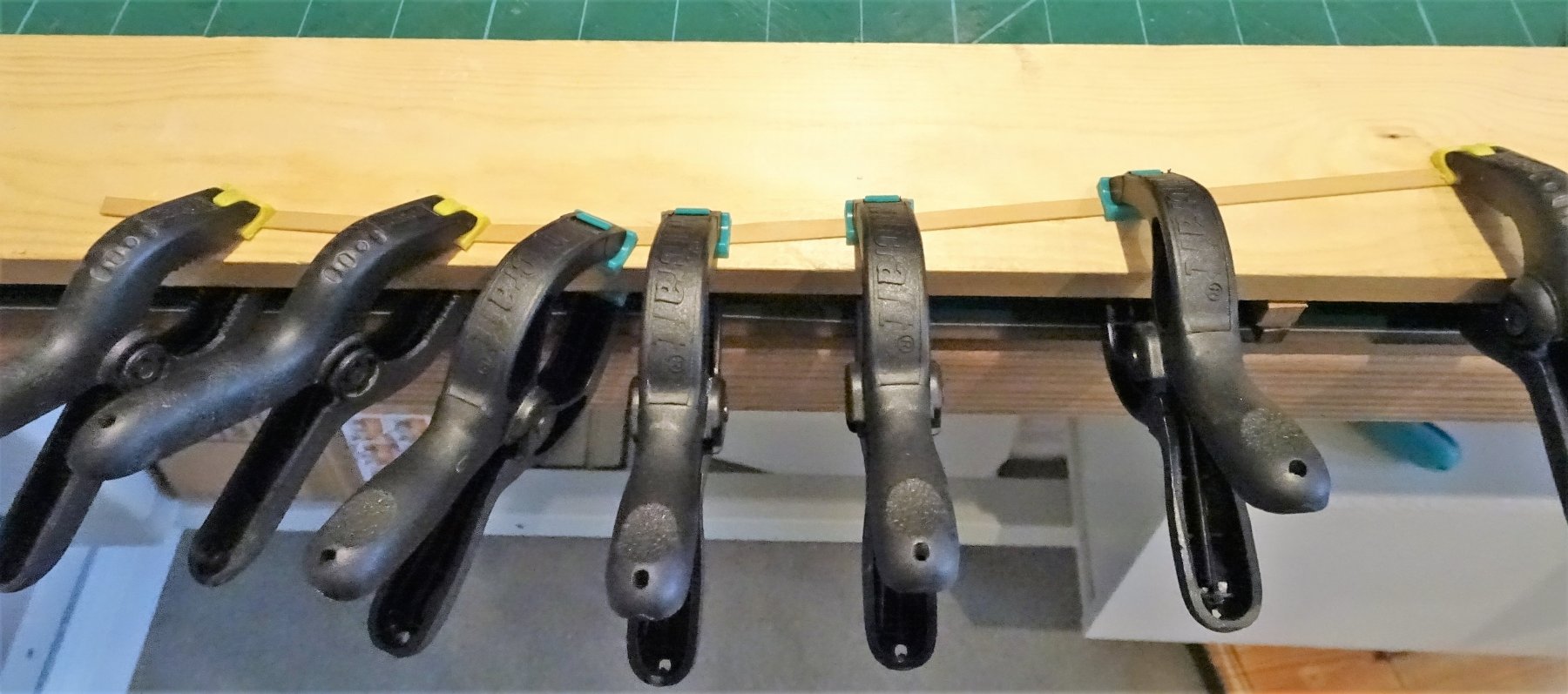
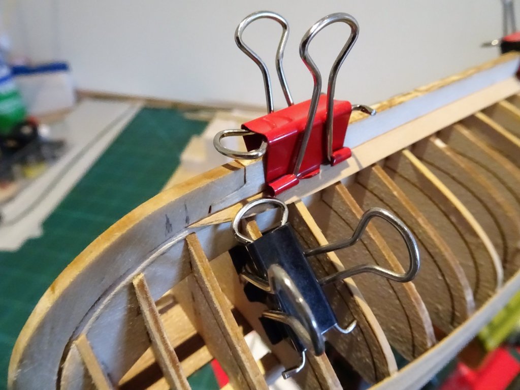
The first Boxwood strake went on well and I think it is firm enough to continue. 7140 Although a little thinner than the provided Limewood, it has a much better finish, and I think it will need much less sanding, so it will probably work out much the same in the end. The crushing and dinking element prevalent in Limewood is also not an issue. I fiddled about some time working out a strategy for the second planks and had a couple of practice runs. 7139 I tapered the plank to 4mm at the bow, starting the taper quite a way back from just forward of Bulkhead A. At the stern the plank was also similarly tapered from Bulkhead 12. The planks will bend to follow the strake line plank, but to reduce tension, once the tapers had been made the strip was given the wet/heat treatment to impart the required curves. The plank was then lightly bevelled on the back top edge, to hopefully get a tight join. A Pilot marker was used to impart a caulking line between the strakes. 7138 I found it a fiddly and frustrating business to get the second planks in place, particularly at the bow area where getting clamps in place to hold the planks during glueing, and if I thought the second plank was frustrating to fit, the third plank has even more shaping involved. Tapers are firstly applied towards the bow and stern, having marked the strips against the hull. I do this with the strip wet and cut the taper with a scalpel. A shallow concave edge curve along the centre section of the plank, with shortish convex edge curves at the bow (b/hG) and stern (b/h11)where the plank meets the stem and transom. The curve around the bow is then formed, all using the wet and hairdryer system. So far so good, but then the plank across the first three bulkheads at the bow refuses to lie flat at the bottom edge, leaving gaps between it and the bulkhead. Seem to be having trouble getting my brain around this build, and to cap a couple of tiresome days I managed to snap off the sheer plank extensions for the decorative transom. Joys of small boat building. B.E.

- 156 replies
-
- 11
-
-
- pinnace
- model shipways
- (and 1 more)
-
Cheers Steve, Michael, and Martin I think William thought I had retired so he's not too impressed that I'm apparently fiddling with a Pinnace. The Pinnace is 11½" long with a 3" beam, Martin, and these first strakes are giving me some trouble, far more rusty than I thought I would be. I don't think in imperial currency now but that doesn't mean I have forgotten how many pennies in a pound,(240 if you're wondering) or our lovely old coins, silver sixpences, Half Crowns, and Florins, the Farthing with its Wren motif, the Ha'penny with its sailing ship. or the Thrupenny bit with its Portcullis. Still reminiscing about our Imperial past won't get this Garboard Strake fitted........... B.E.
- 156 replies
-
- 4
-
-
- pinnace
- model shipways
- (and 1 more)
-
Kind of you to say so John, and enjoy your new build, the Swan's make great models😊 B.E.
- 366 replies
-
- 1
-
-
- pegasus
- victory models
- (and 2 more)
-
Thank you Christos. B.E.
-
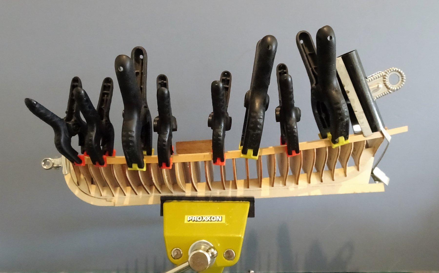
With the fairing completed the stern transom is added. 7026 This has very little to hold it securely at least until the first strakes are added, so I also drilled and pinned it to the false keel. Even so very soft hands are required to fair the transom piece. As a trial I am using 0.6mm thick Boxwood strip, slightly thinner than the provided Limewood. 7033 The sheer strake is applied full width. PVA is used to bond the strip to the b/heads, secured with an assortment of clamps. 7032 7051 Water and heat are used to bend the strip both laterally to follow the rise of the sheer, and to curve around the bow. 7053 7058 7055 The foremost Bulkhead K rises above the sheer line. 7060 The Sheerline strake extends beyond the transom. When I made the mini version for Pegasus I omitted the second decorative transom piece, still not sure what practical purpose, if any, this addition served, but as they were a feature of the 18th Century Pinnace, I will include it on this build. Once the glue has hardened overnight I will add the next strake, and then make a decision whether to continue with the Boxwood, or remove and revert to the Limewood. 7038 C'mon ain't you spent enough time on that today. B.E.


- 156 replies
-
- 22
-
-
- pinnace
- model shipways
- (and 1 more)
-
Contrasting hull colours look great Michael, the black wale sets them off a treat. B.E.