


RdK
-
Posts
120 -
Joined
-
Last visited
Content Type
Profiles
Forums
Gallery
Events
Posts posted by RdK
-
-
-
On 1/10/2021 at 7:15 PM, Ab Hoving said:
Looks good Jan!
Shouldn't there be brails on the front side of the sails?
Great job man,
Ab, I was thinking the same...😄
And how about mizzen top-sail bow-lines and 'martnet and brails' on the mizzen? Were they on the Anna Maria?
Beautiful model, Jan! Makes me more and more want to do the "Hollandse Tweedekker" I have on my list! 👍
-Radek
-
Hi there and privjet!
Since I have seen your lightning on instagram I wanted to build a model with lights as well. I think it was your model, but it was 2 years ago or more. I am happy to see your build here on modelshipworld!😃
I use four strings of serial LEDs with 11 LEDs on each string.
The circuit board to distribute a flickering effect (to imitate candle light) will be in a small box on the stand under the ship. That way I do not need to buy 44 resistors... I use also only 6V battery (2 x 3V). Four LEDs with random flickering serve as the circuit for the flicker-effect and are distributed via a chip to the four serial strings. So I have four random flickering effects, which I distribute through the model. I will explain soon here when I will start to post my progress on the ship. As a ship I chose the fictive Spanish Galleon Neptune from the movie "Pirates" by Roman Polanski. So far I have found only one model of it, that has been made by a Russian Modeler named Vitaly Maslov. I could not find much information about his build, only a few photos.
My model, like my previous one, is being made from paper and cardboard...😊
Here's a video of my trial:
- mtaylor, Ian_Grant and dantist905
-
 3
3
-
Hi!
Thanks Nils for the nice tutorial!
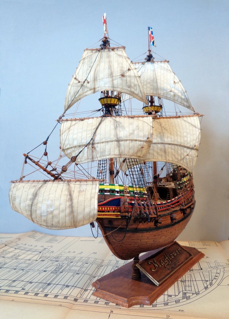
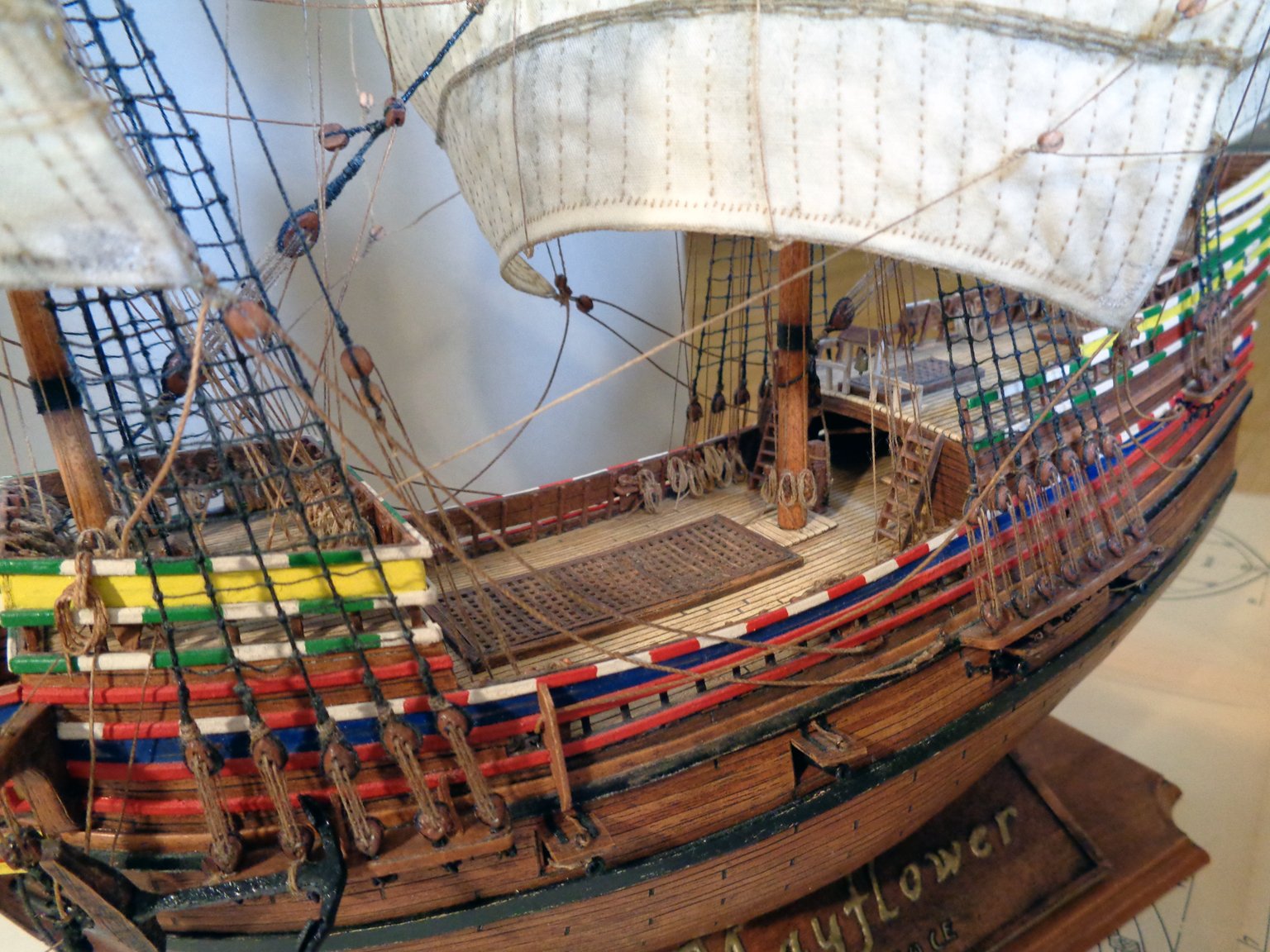
While I also agree that stitches are always way out of scale, sometimes it adds to the charm of the model. I wanted stitched sails on my Mayflower, scale 1:100, which seems ridiculous, but I am very pleased with the result.
However, the catch is that I stitched it all by hand... 😅
-Radek
- mtaylor, Jorge Hedges and Mirabell61
-
3
-
Hi,
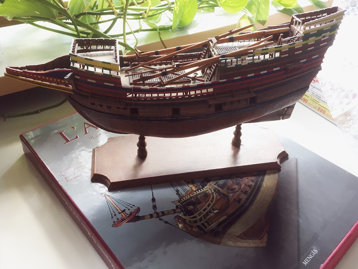
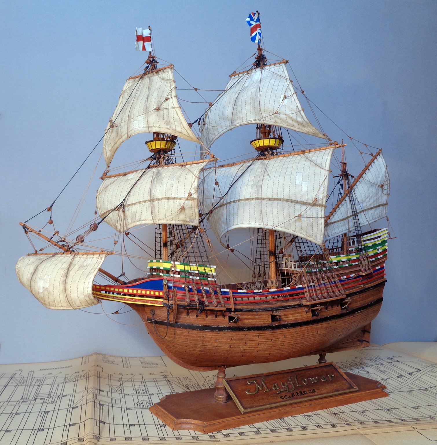
Thank you for the likes and congratulations. I asked my friend to make better photographs of the model, which I now present in the Gallery.
See you around the forum!
-Radek
- laarmada, mtaylor, Ryland Craze and 2 others
-
5
-
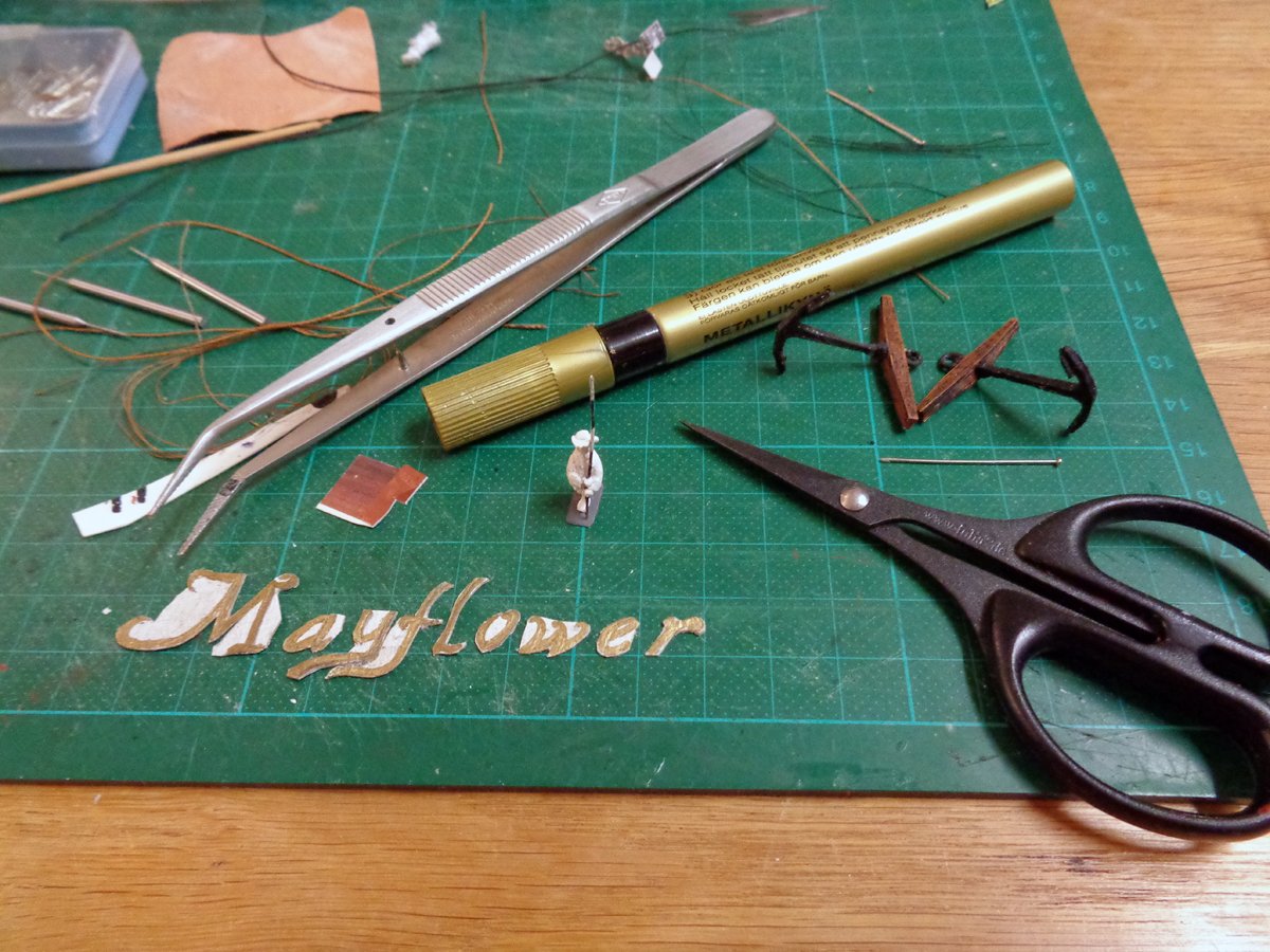
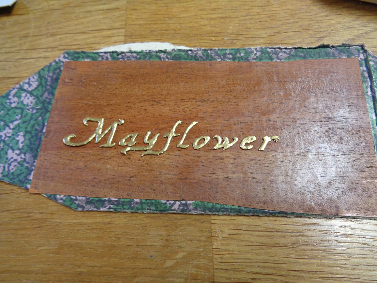
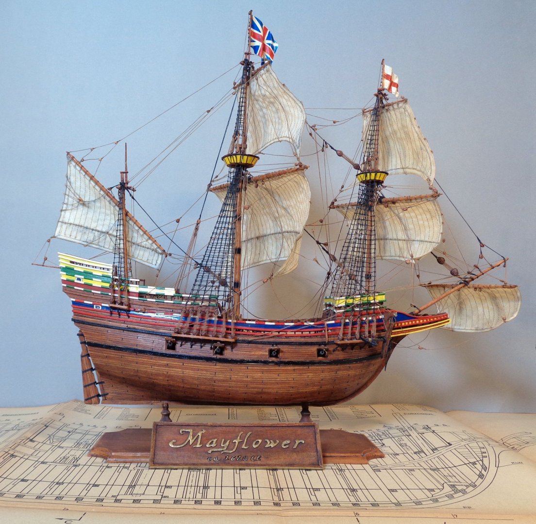
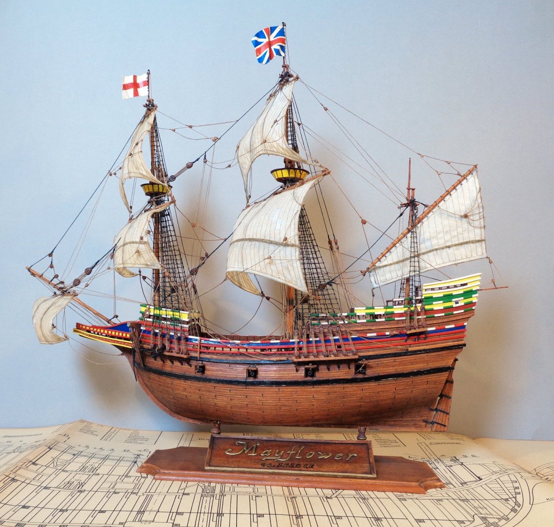
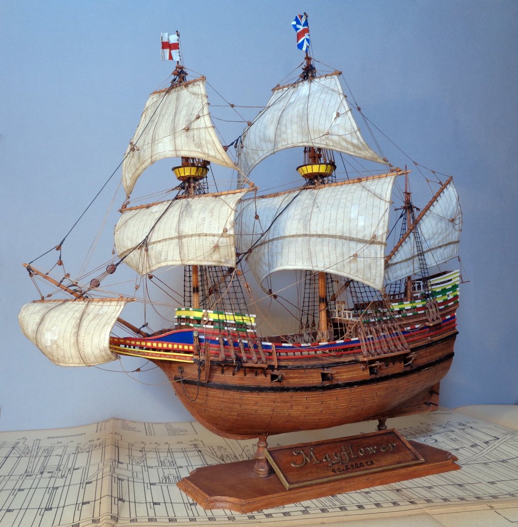
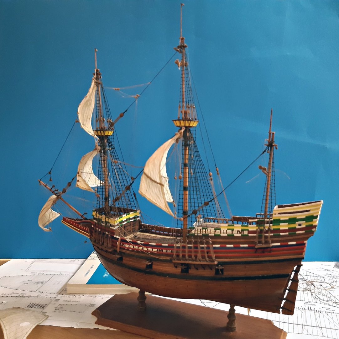
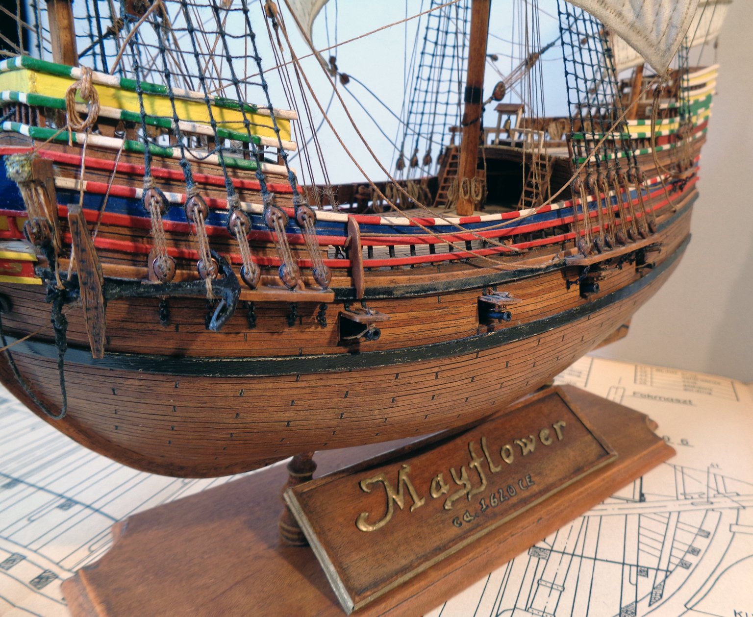
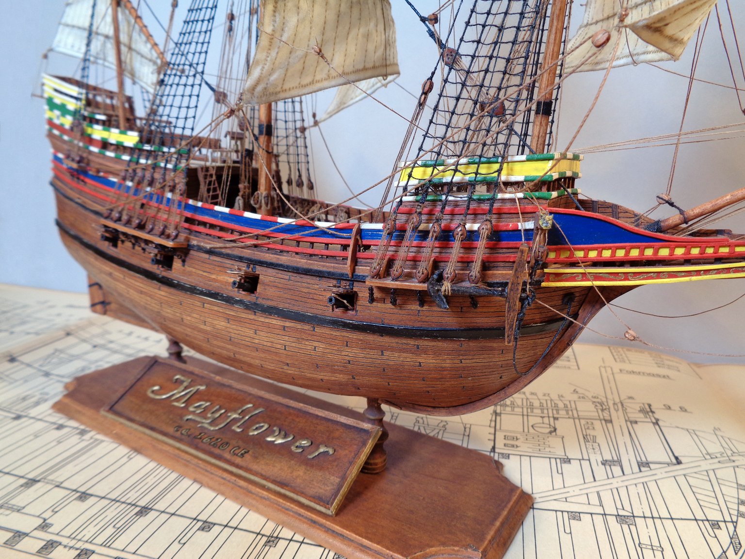
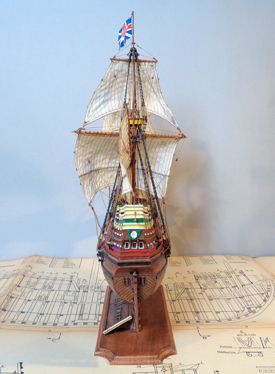
Name tag for the stand and the finished Mayflower...
Thank you all for the likes and comments! 😊
...So I finally finished the model this week, after a journey of 10 years with ups and downs, the survival of the harsh, cold north and a completed study in geochemistry...
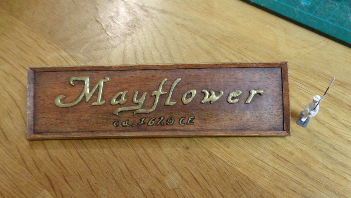
Here are some pictures about the name tag, which is of course made entirely from card. I used some thicker card with the self adhesive foil with wooden patterns on both sides and altered it with oil paints. The letters were drawn and then cut from a pizza box. Then I used a golden waterproof marker to give the letters a bit of a 3D-appearance. Worked out to my satisfaction. The edges were also painted golden.
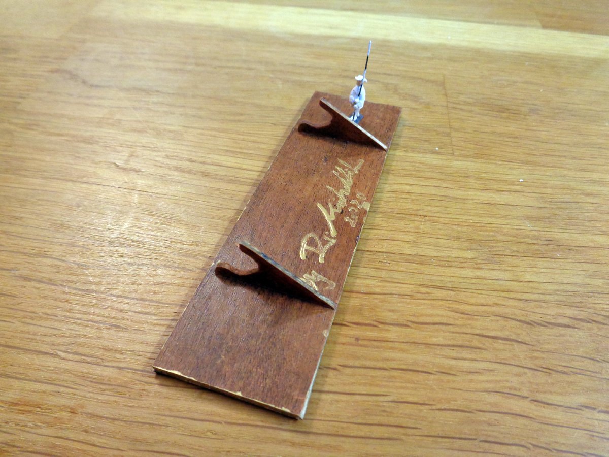
After glueing all parts in place, I "signed" it on the back side and still altered the edges around the letters and the sign a bit more with black oil paint.
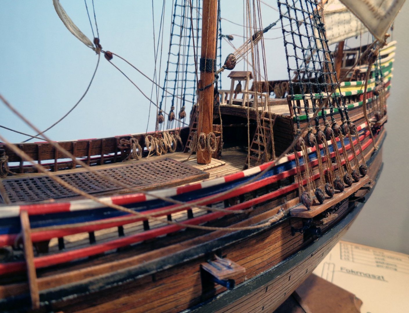
The rope coils for the deck were at the beginning a complete mess because the CA-glue soaked in them totally, making them look like chewed and spit out again... 😕 I changed then to the CA-gel, which was much better to apply, but still I made some mess in the one place or another...
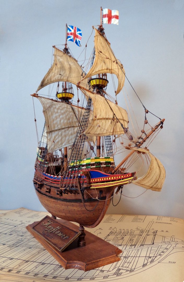
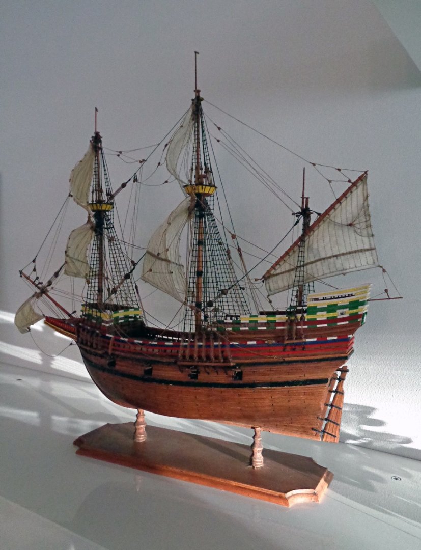
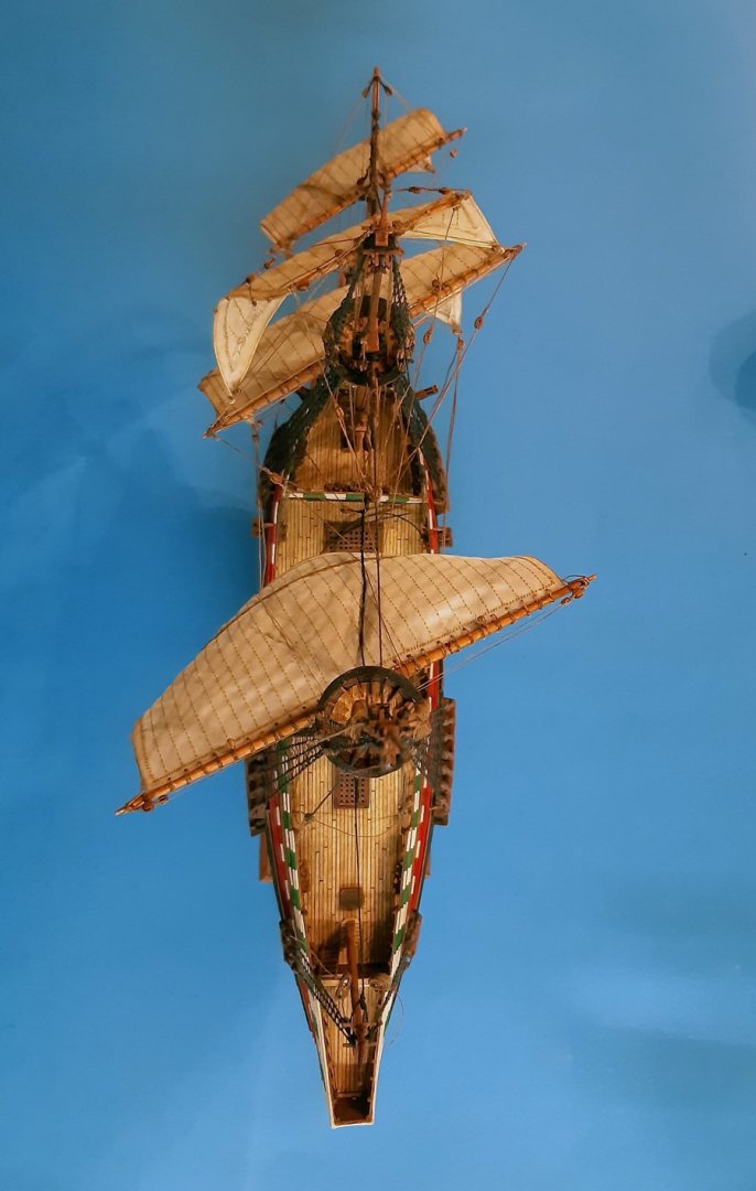
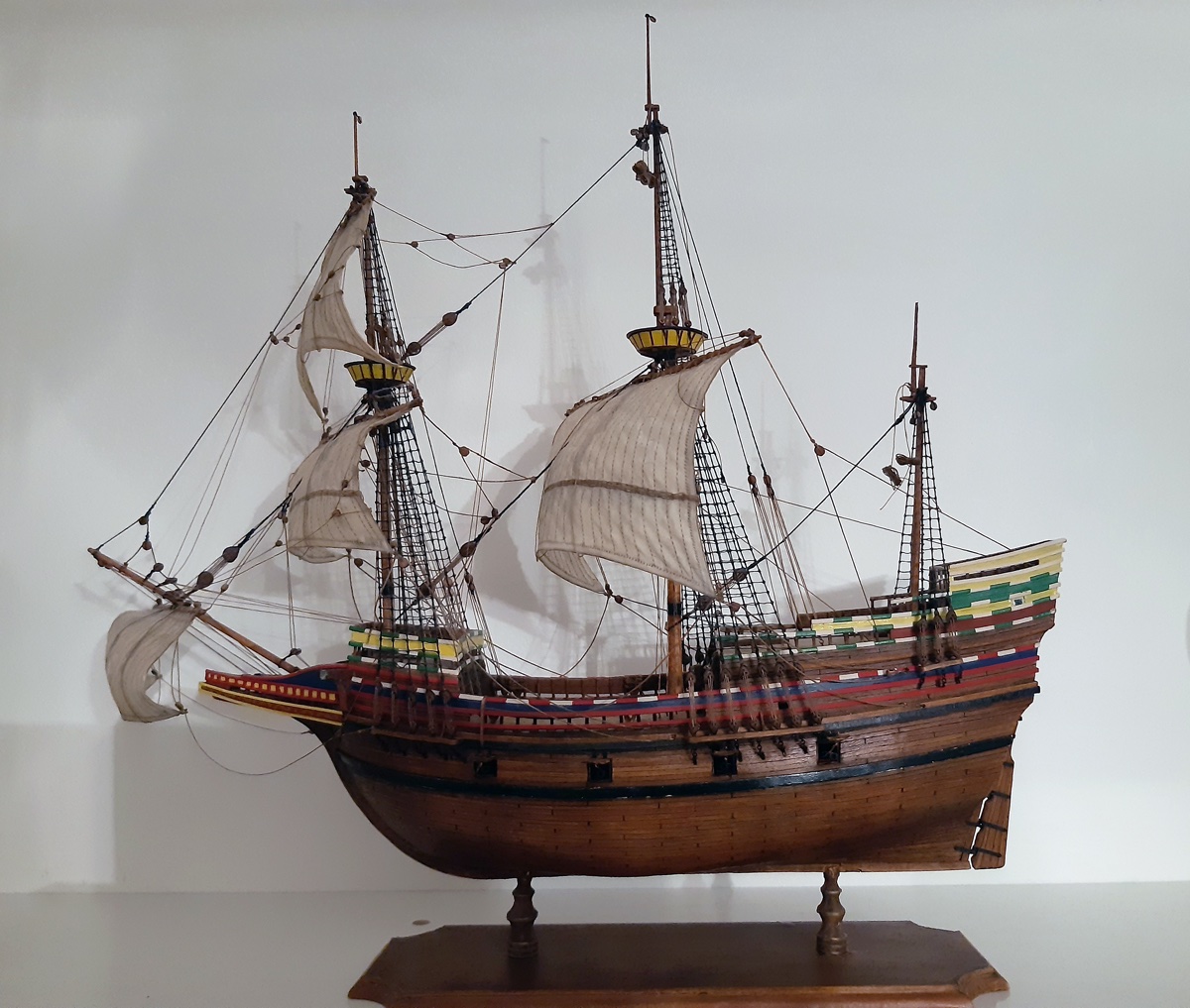
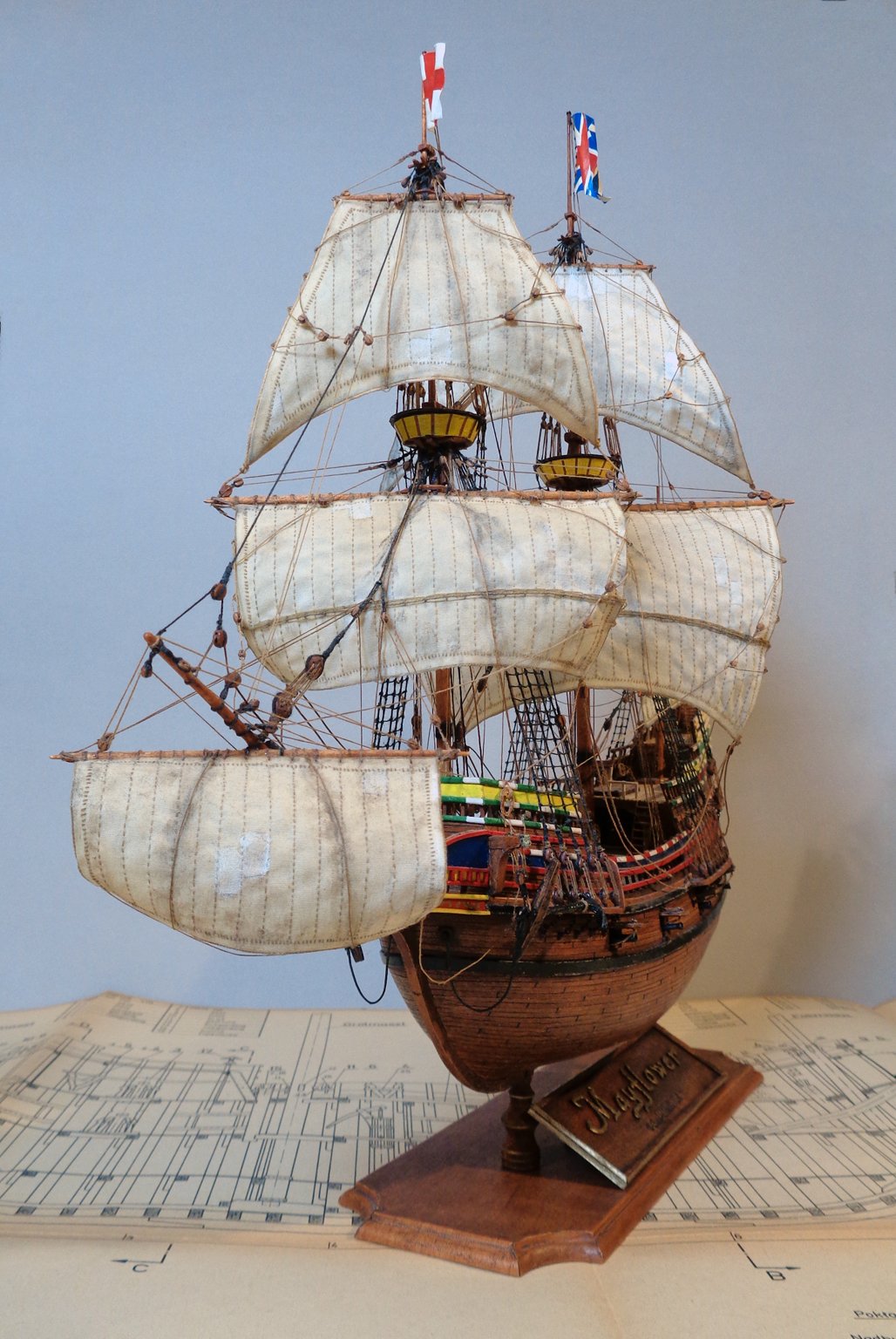
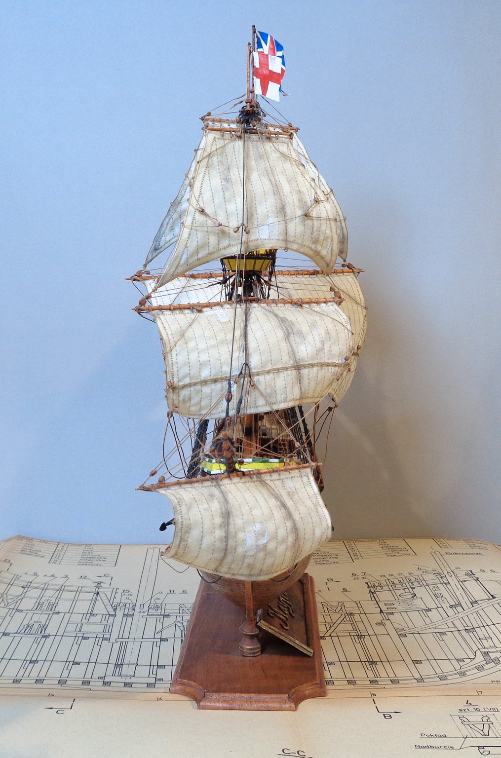
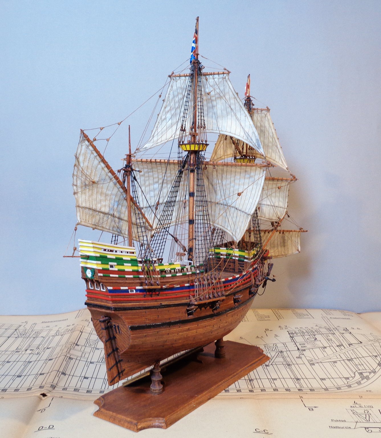
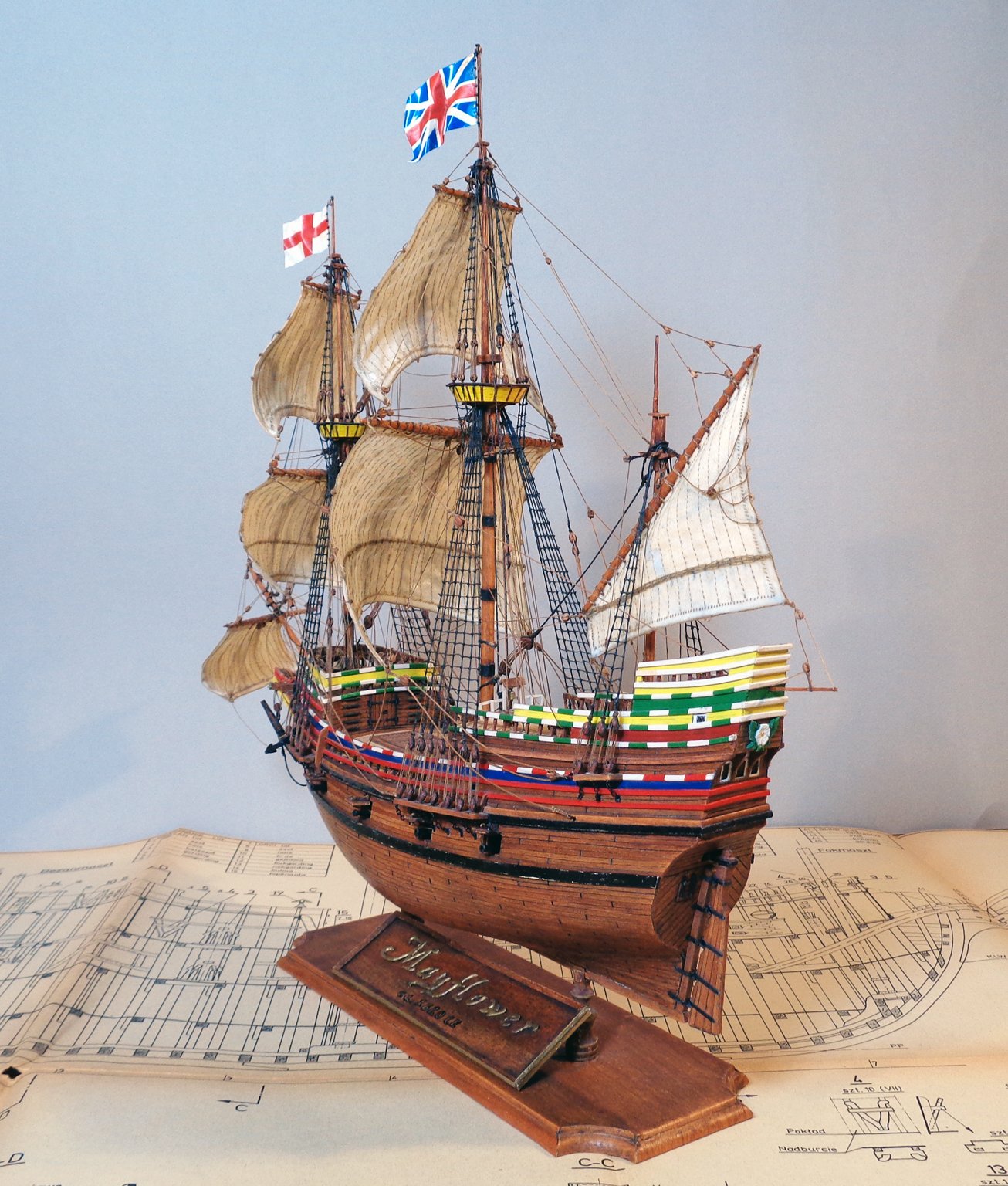
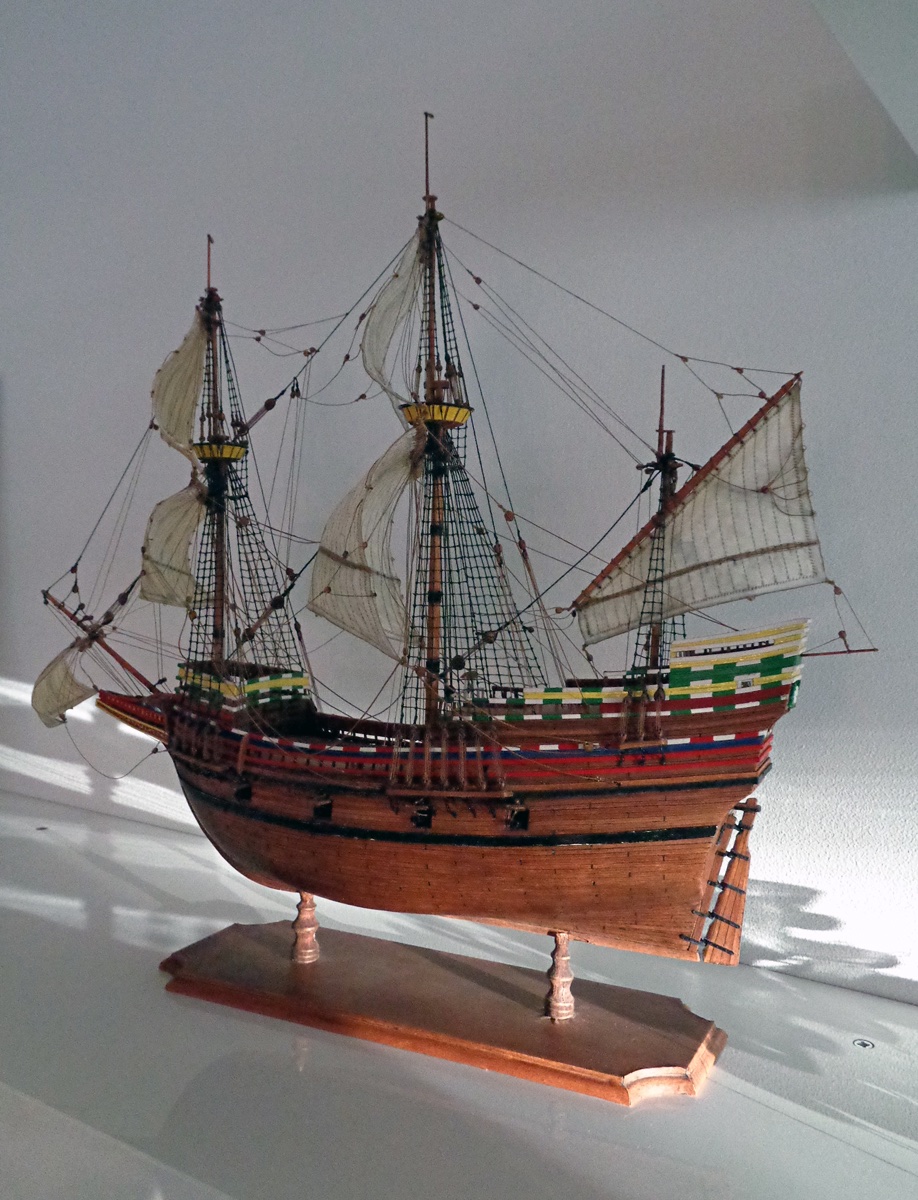
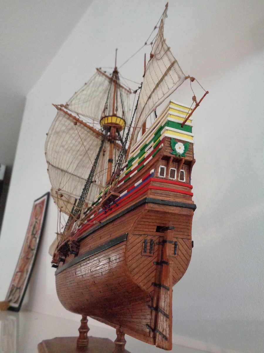
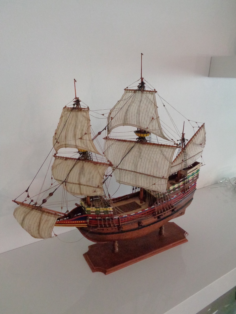
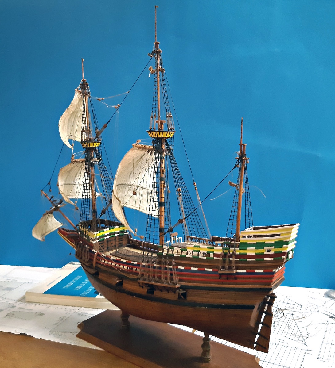
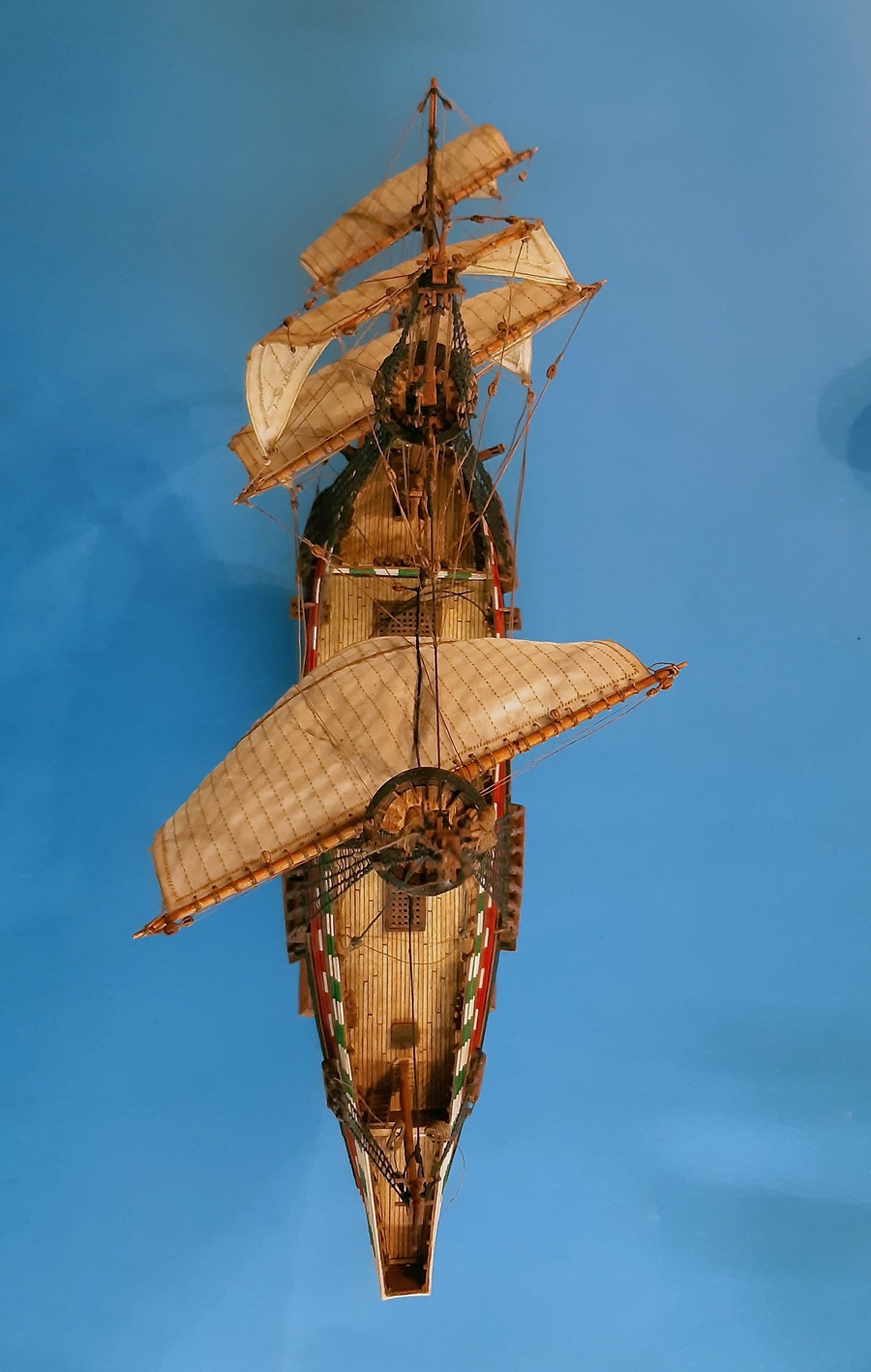
And here some pictures of the finished model:
The MAYFLOWER , based on the plans from Waldemar Nowy (1976) from
"Plany modelarskie, Vol. 78, Nr. 2, 1977"
Waldemar Novy in turn based his plans on the plans for the Mayflower II, by William A. Baker (1958).


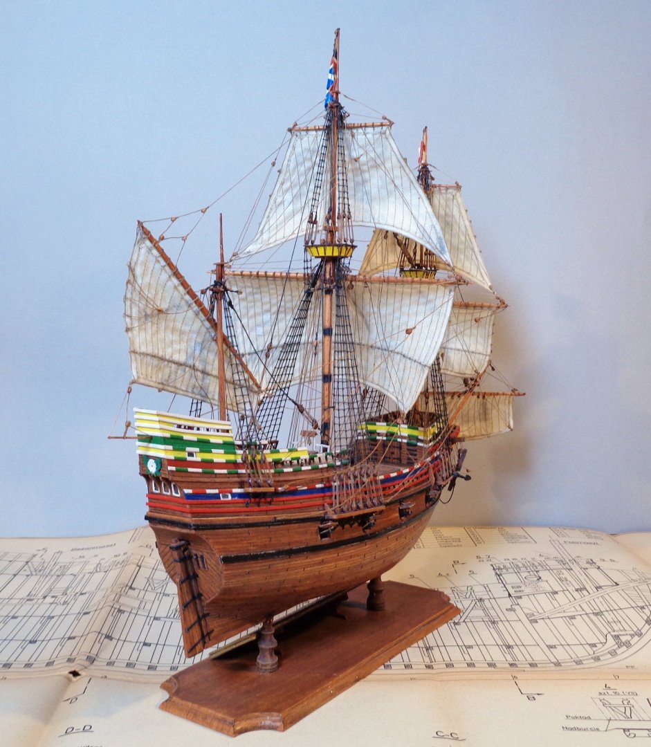


I will try to make some better pictures and post them in the Gallery as soon as I have borrowed a better camera with a tripod.
Kind regards,
RdK
-
6 hours ago, mhkash said:
Hi Radek ,
Excellent work and great shots, I really find what you are doing is amazing , the Guns part is splendid .. will do the same with my current build
thank you for sharing
regards
Hi and Thanks. The shots are just snap-shot camera shots. Often the images are grainy or not as sharp as they used to be with my old camera. Building the cannons this way is typical for paper modellers...
")
-Radek
-
Cannons, Sails and Flags
Hi all!
Here a bit about how I made cannons, sails and Flags.
Rolling thunder...
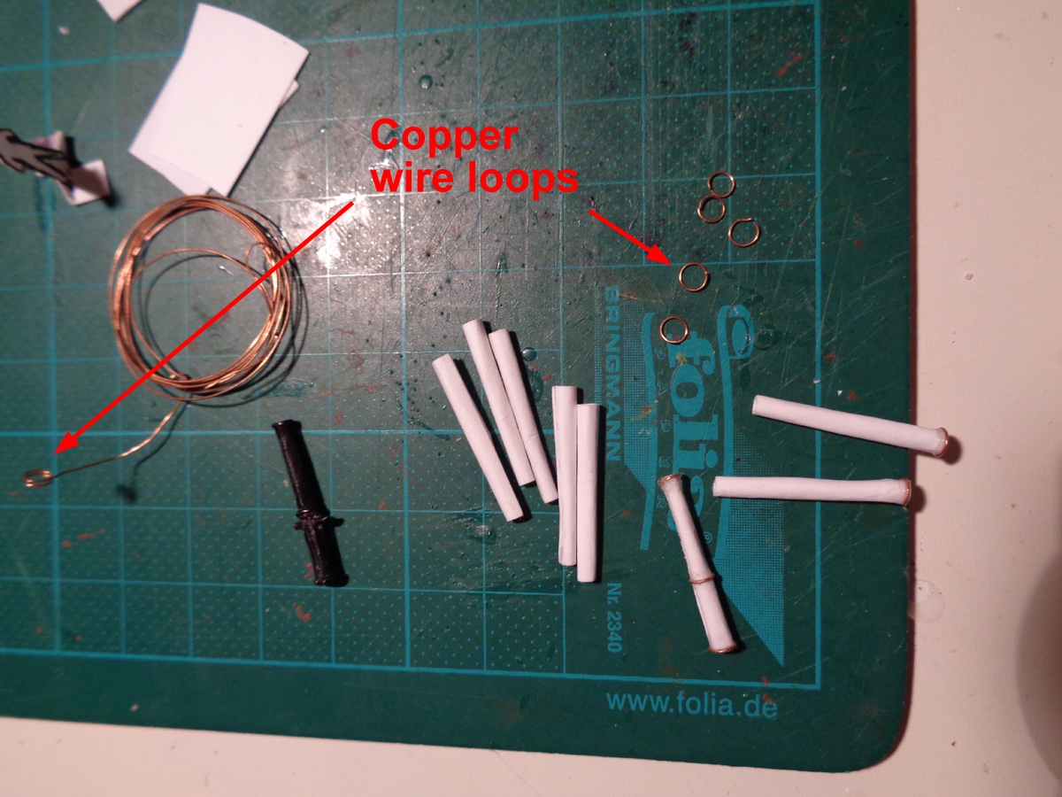
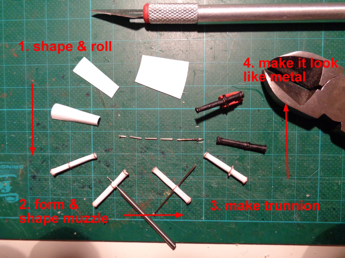
Making cannons from a slightly thicker paper is really easy when comparing with the magnificent ones carved from wood or cast from real metal. Also in this model scale 1:100 and with them not really visible, there is no need to make them exactly as they look in real. For instance you cannot see the cascabel so there is no need to do it. So I decided to simulate only the muzzle, muzzle swell, and trunnion of the cannon and make a simplified cannon carriage without wheels and any rigging. The Mayflower was equipped with at least one minion cannon, which is about 7 feet (2.2 meters) long, so I rolled eight of these.
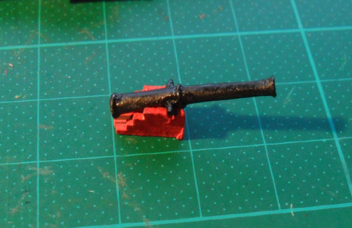
I used card for the barrel, some copper wire for the muzzle and the other reinforce rings. For the trunnion I cut a pin into the right size. The muzzle swell was imitated with some CA glue. In the end I coated the cannon a bit with CA for integrity but also because the black marker, when applied on CA gives a slightly metallic luster. Important is that it is acetone free, as acetone will dissolve the CA!
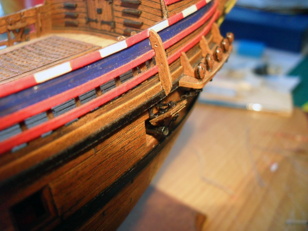
The gun carriages were placed in position already before the planking so all I needed to do now was to glue the cannons in place.
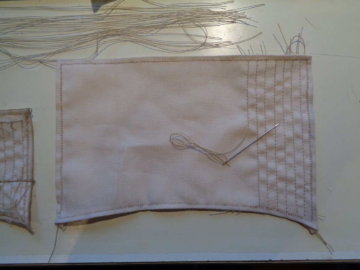
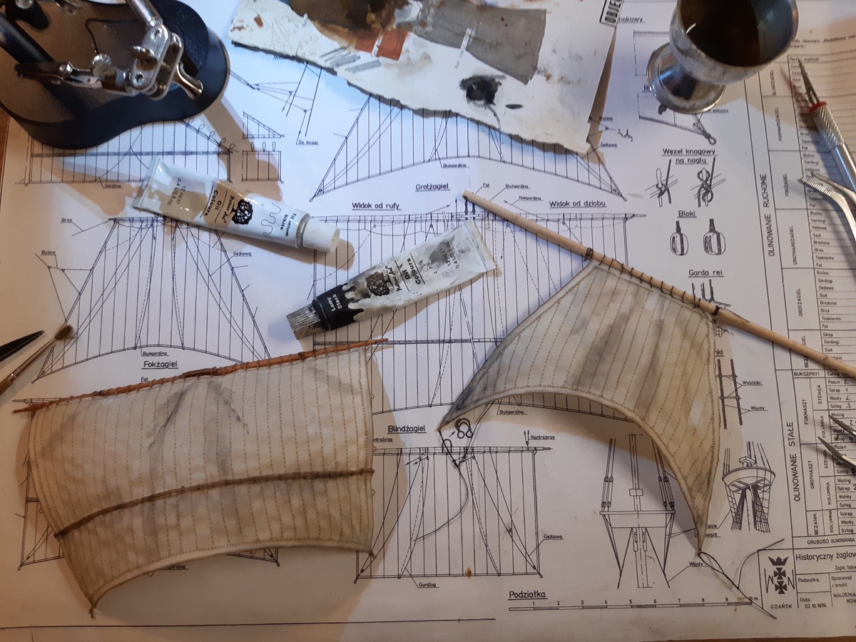
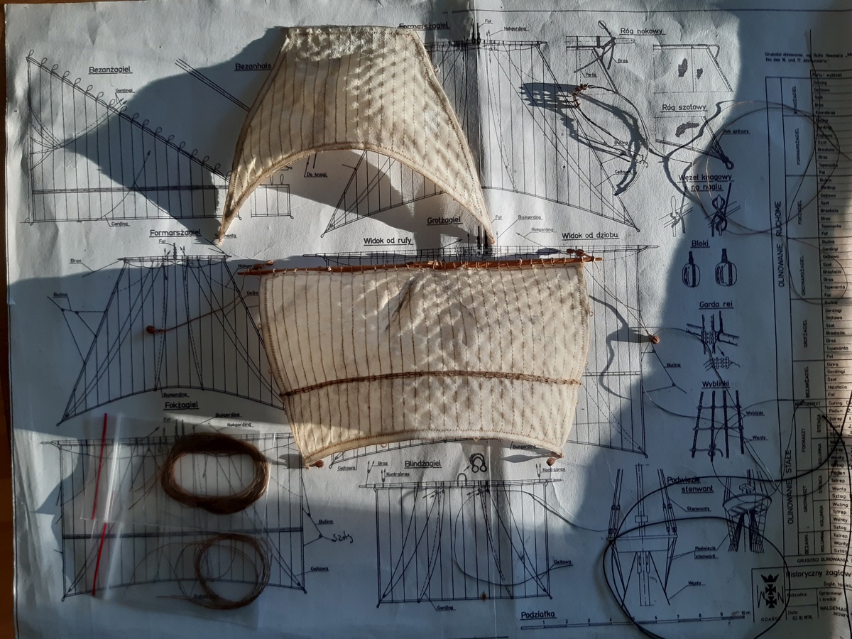
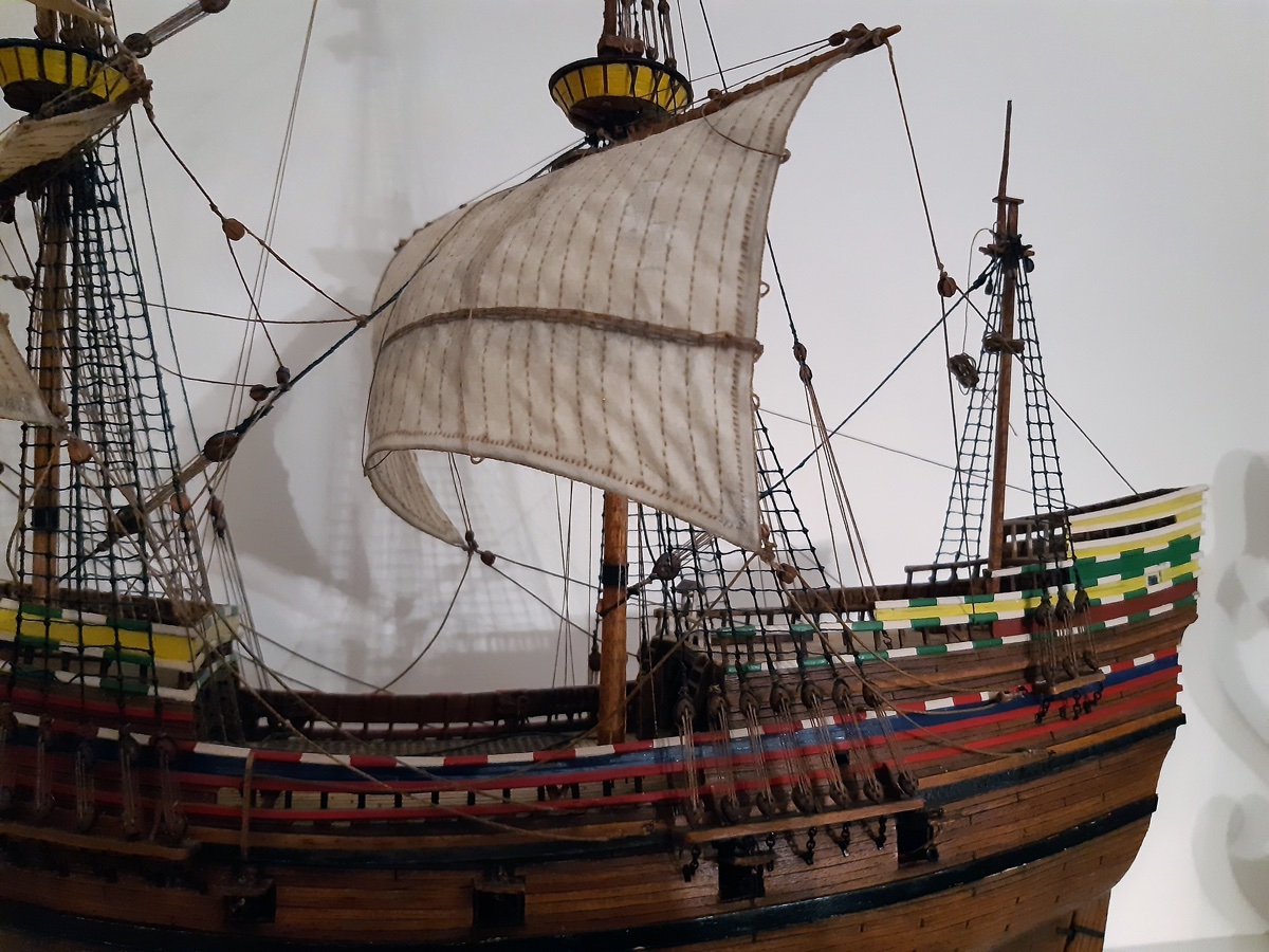
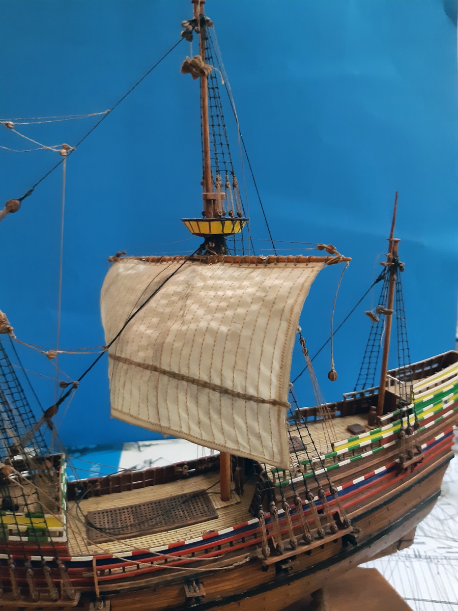
The sails...
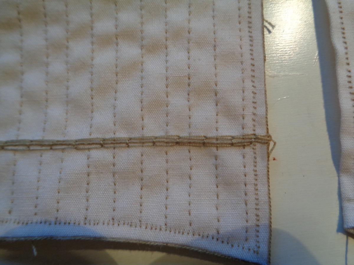
With the sails I wanted to achieve an antique, rustically model appearance, yet I wanted the sails to look dirty, as if they were on a long journey. So I chose as material an old white shirt from fine linen. I colored it with black tea. Then I cut them out with a small margin of 5-10mm, which I then bent and thus saw the edges. Then I imitated the seams of the individual panels by sewing (more or less) straight lines down the sail. The edges were then sealed with CA. Next time I might skip the sawing, but I must admit it was surely relaxing after a long working day, listening to the ticking of the clock and the afternoon sun shining through the window...
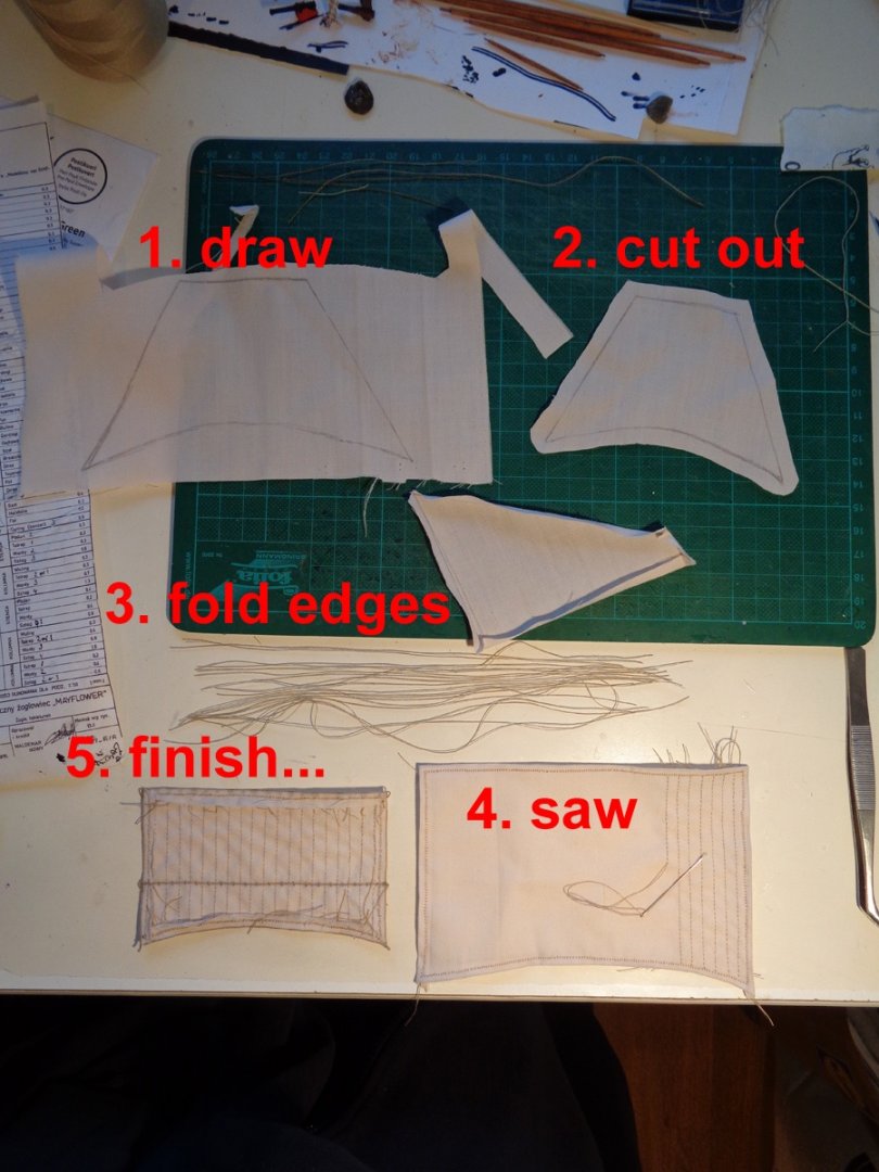
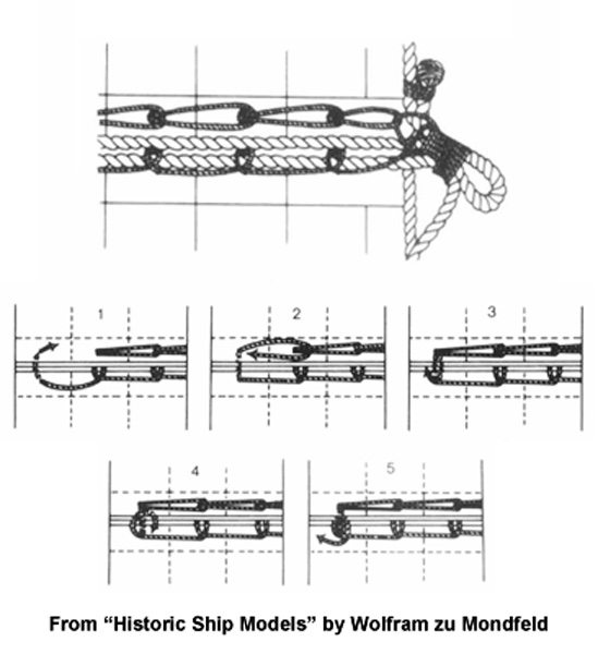
Where a bonnet is used, I sew it according to the pattern from zu Mondfeld's "Historic Ship Models":
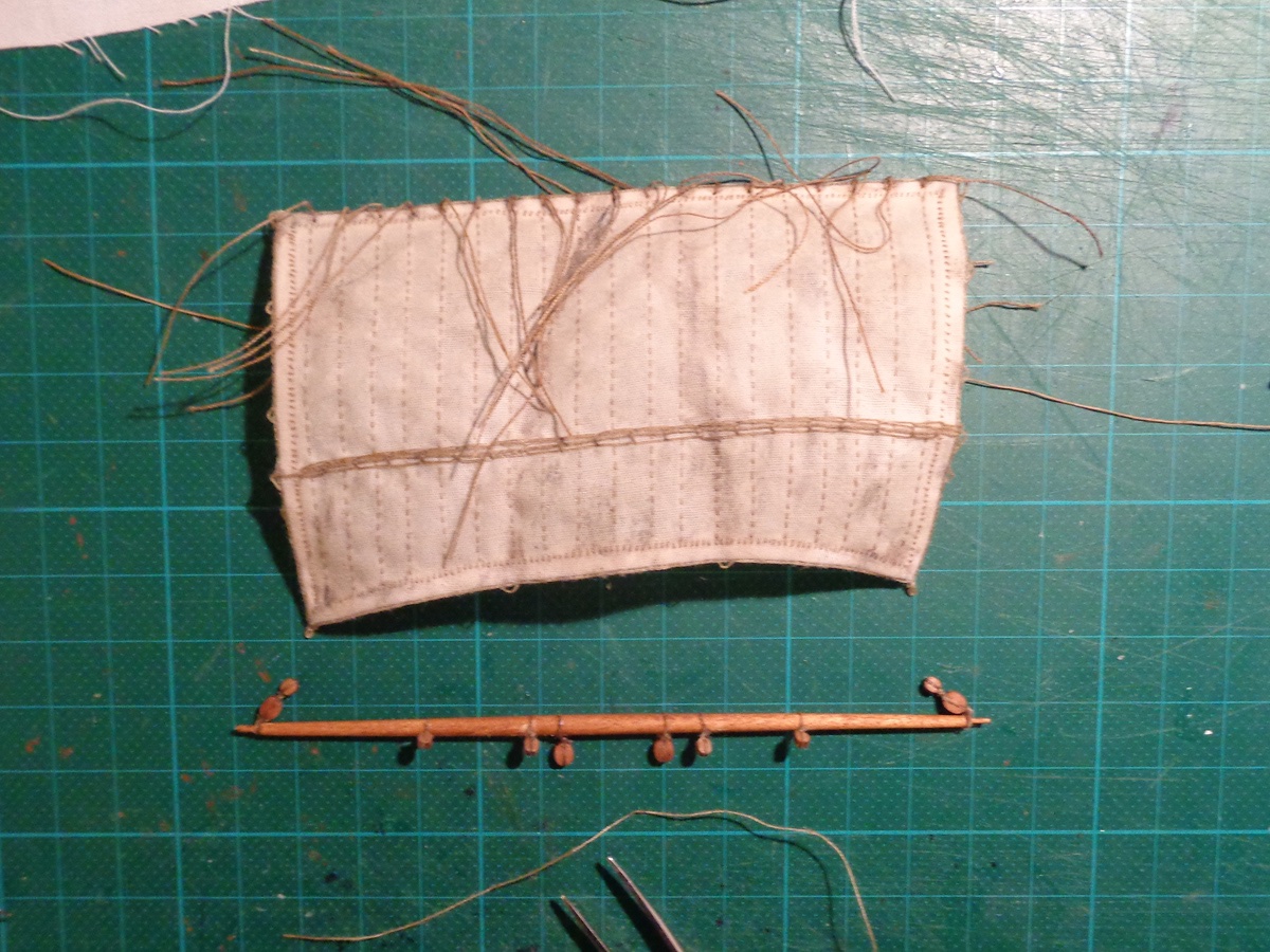
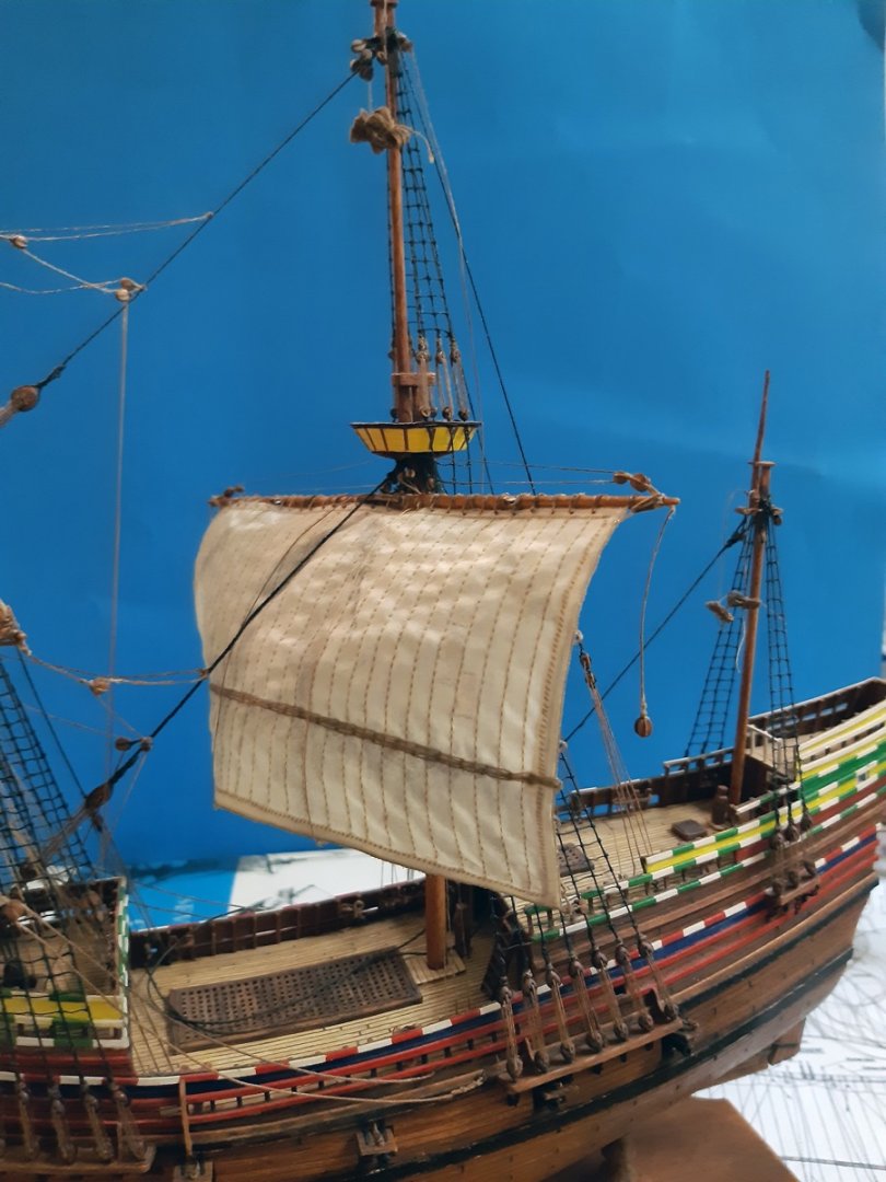
The ready sails I then shaped into a blown form by using some sand and clear varnish. This is a method I found in one of the polish ship model forums long ago... First I mount the sail onto a stick imitating the yard, attach it from all four corners into a hanging position, weight it with a bag of sand and cover it with the clear varnish from the bottom. But I still have to work on my execution of that method or use just simply some white glue instead of the varnish.
Once the sails were dry I altered them with oil paints and attached to the yard, prior to attaching them to the ship.

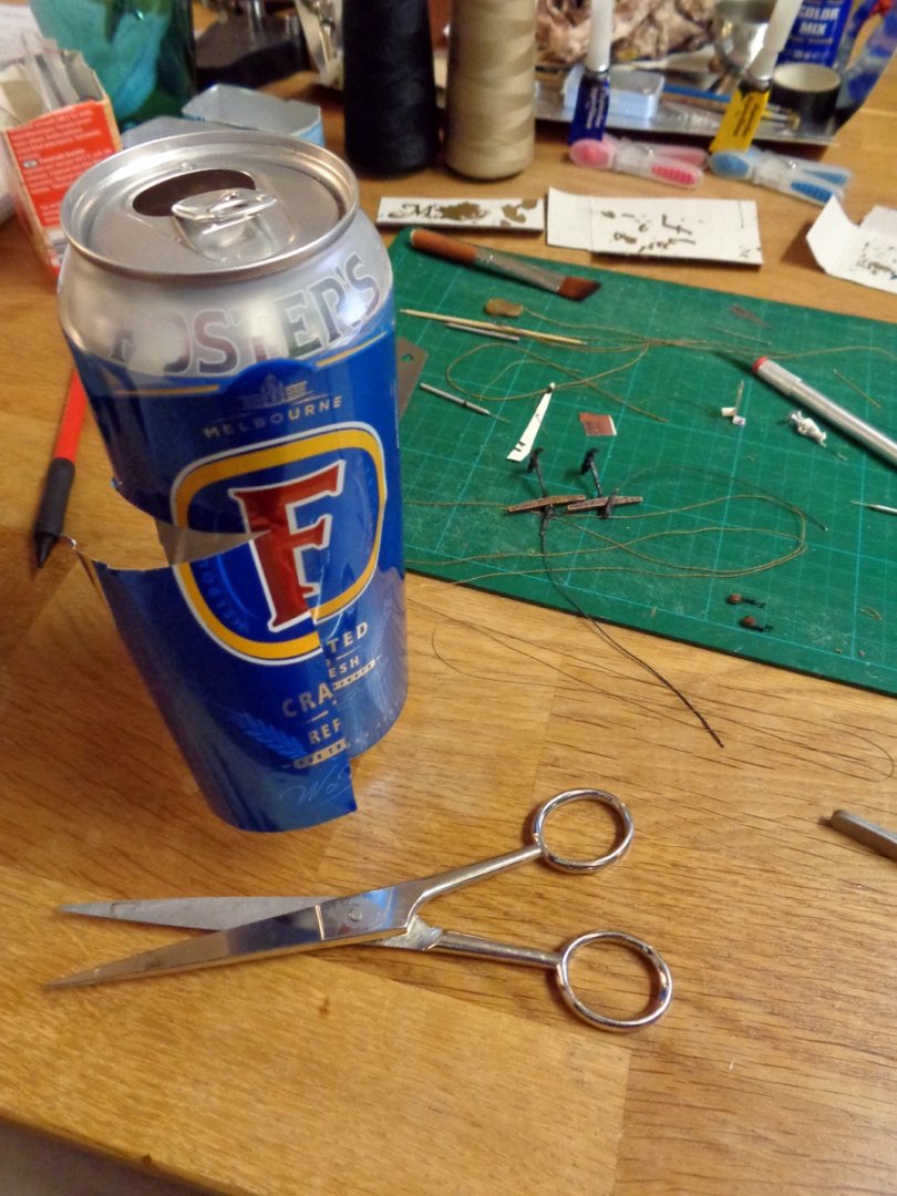
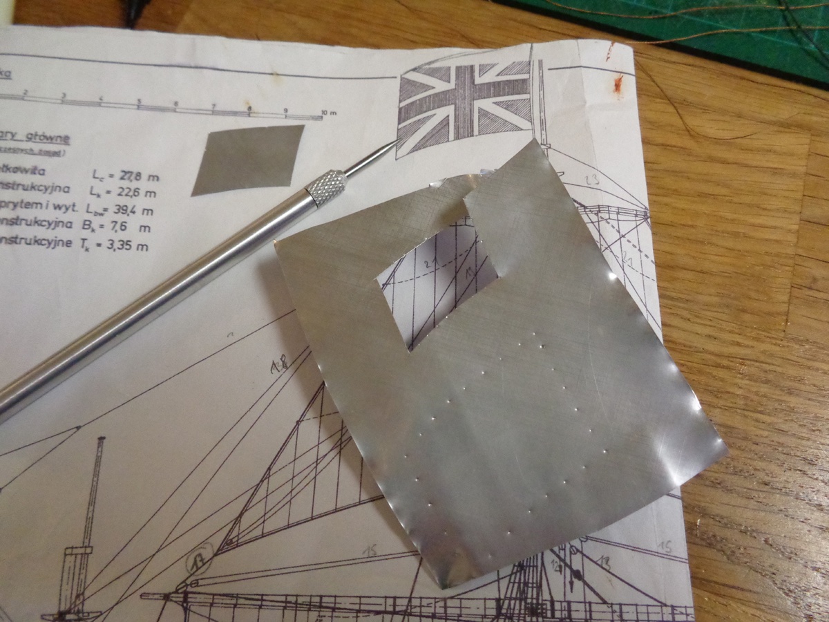
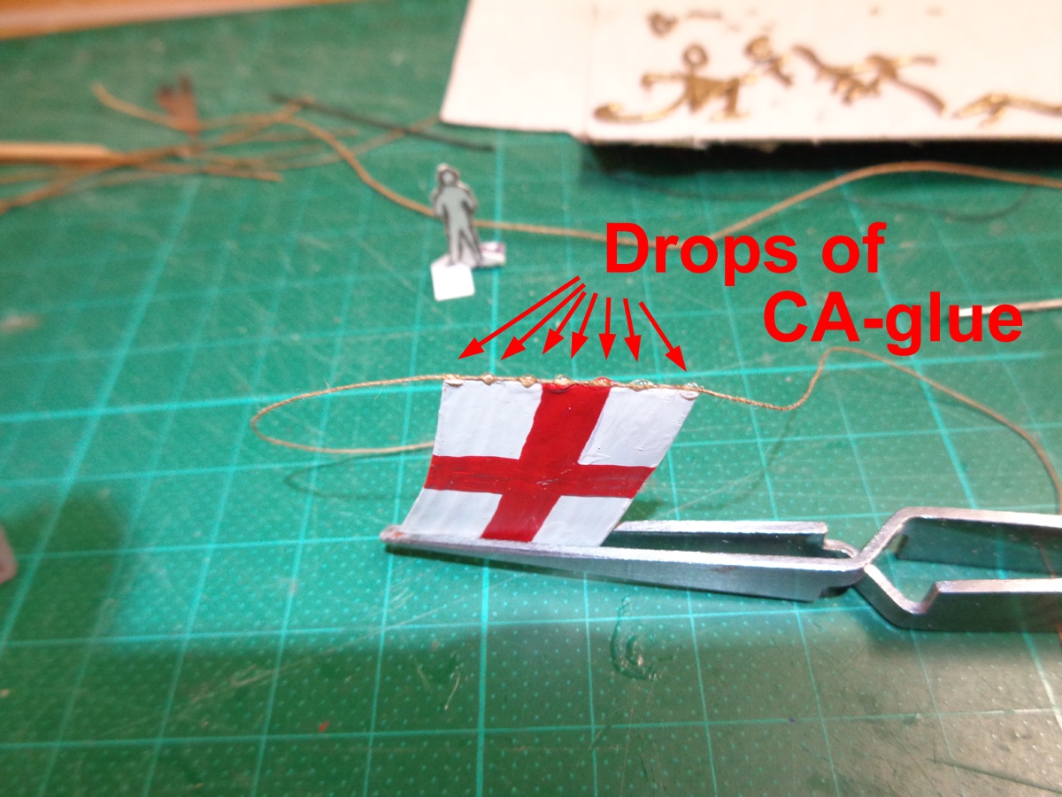
The Flags...
The method to make flags is also an old one. In order to shape them into a wind-blown appearance I use metal sheets and not fabric. For that I first drink my beer...😋 Then I copy the flag dimensions onto the sheet by simply piercing them through the plans onto the underlying sheet, preferably a bit outside the dimensions so when cutting, the piercing marks won't be visible on the edges. The flag is then painted with enamel paints (the ones for plastic models) and altered (with turpentine-diluted oil paints) if needed or wanted, and then bent into the desired shape. The attachments to the halyard were imitated with drops of CA-gel glue and colored black with a marker.
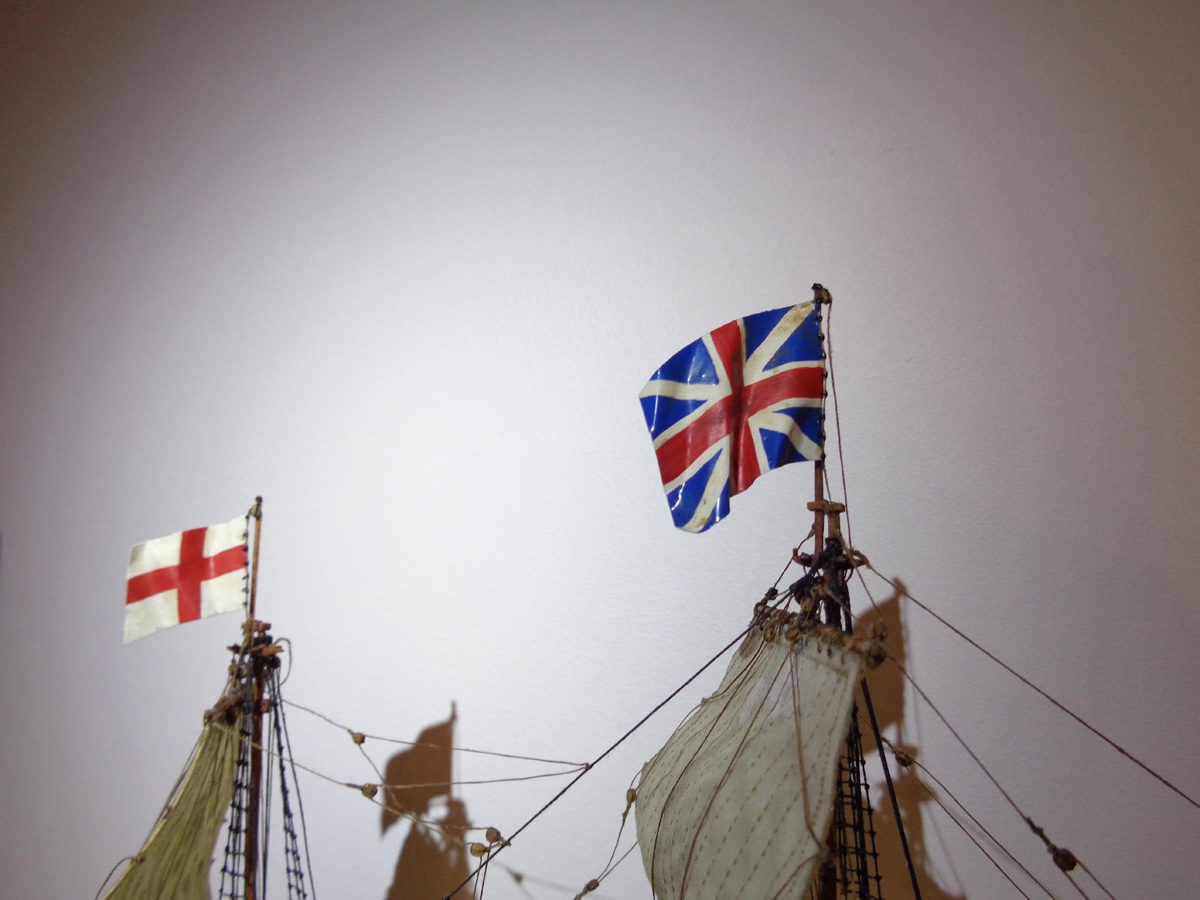
So much for now. I finished the Mayflower this week and will post the pictures of the finished model as well as a small description of making the name sign for the stand tomorrow or so.
Rgds,
Radek
- GrandpaPhil, mtaylor, daHeld73 and 2 others
-
5
-
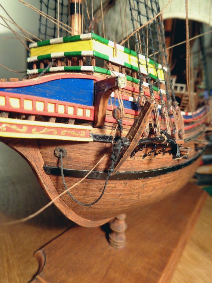
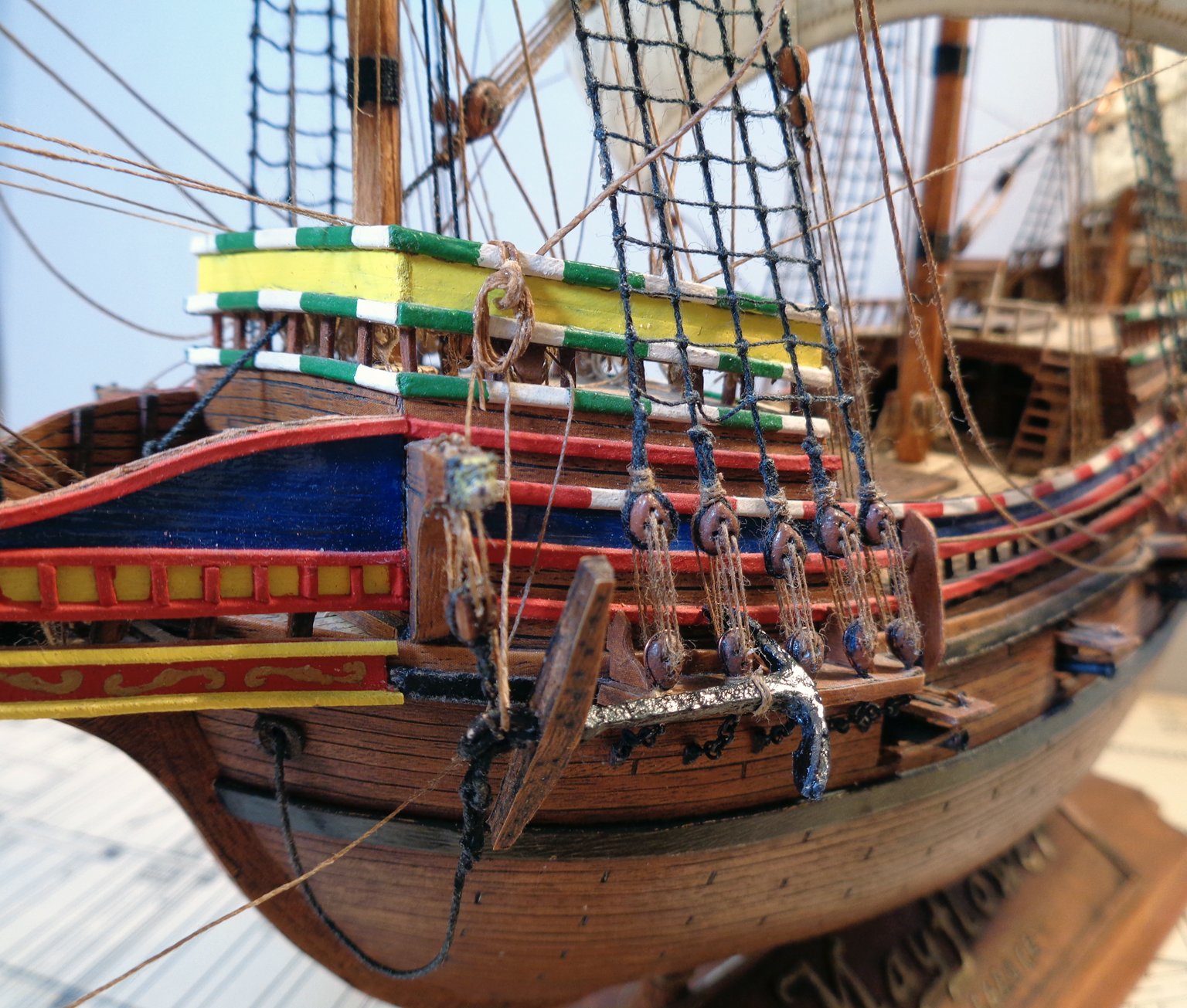
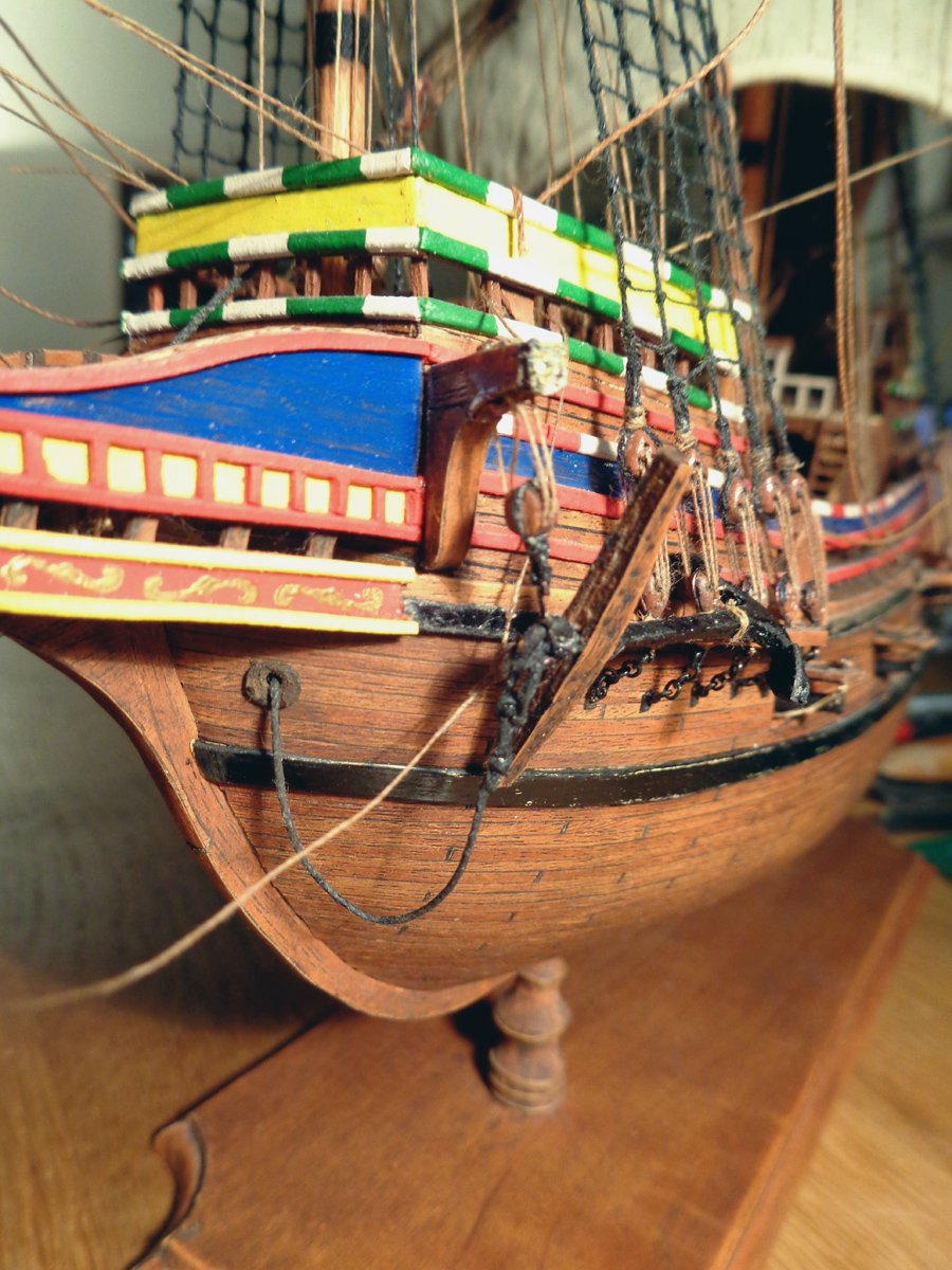
Anchors...
Hi all!
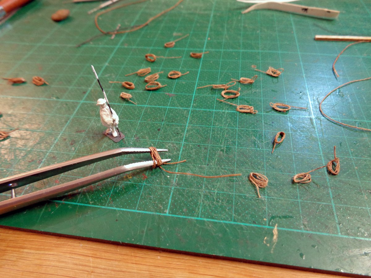
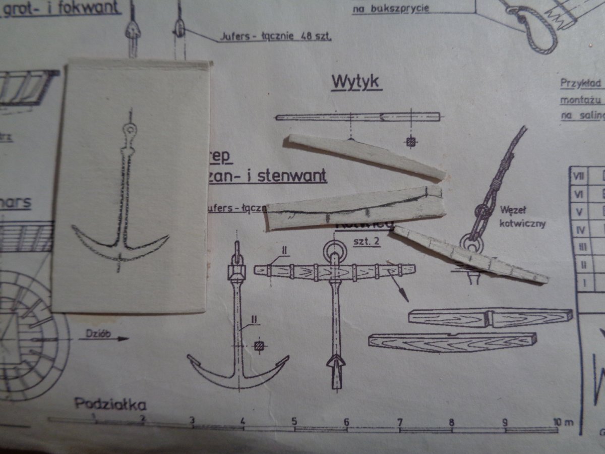
Here a bit about my way of making anchors (sails and flags in the next post). The anchor I made from the original plans by Waldemar Nowy turned out to be from a too modern era, as pointed out by Ab, so I followed his advise, made some additional research and did them accordingly.
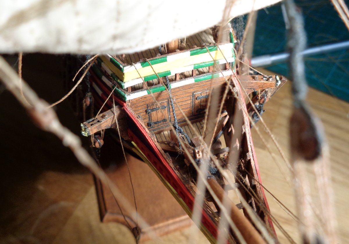
I used some 1 or 1.5mm card, copied the anchor shape on the card by piercing through the plans onto the underlying card, drawing the lines and cutting out with scissors and scalpel. Here some images from my first try:
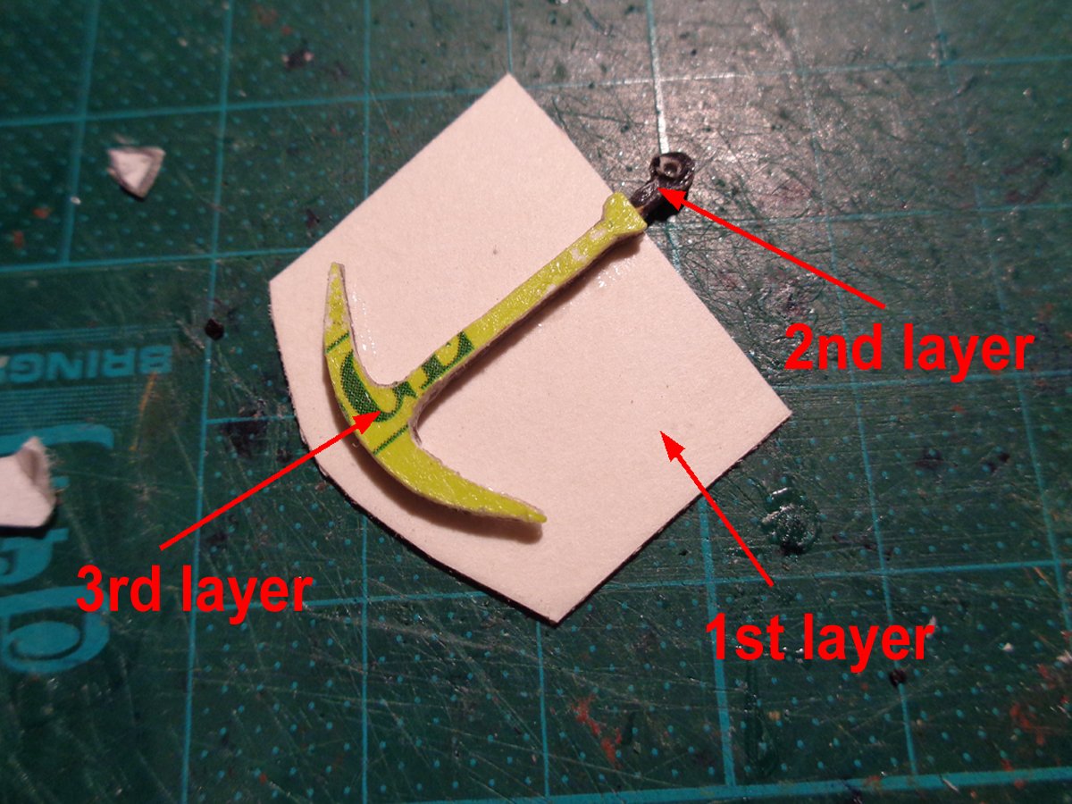
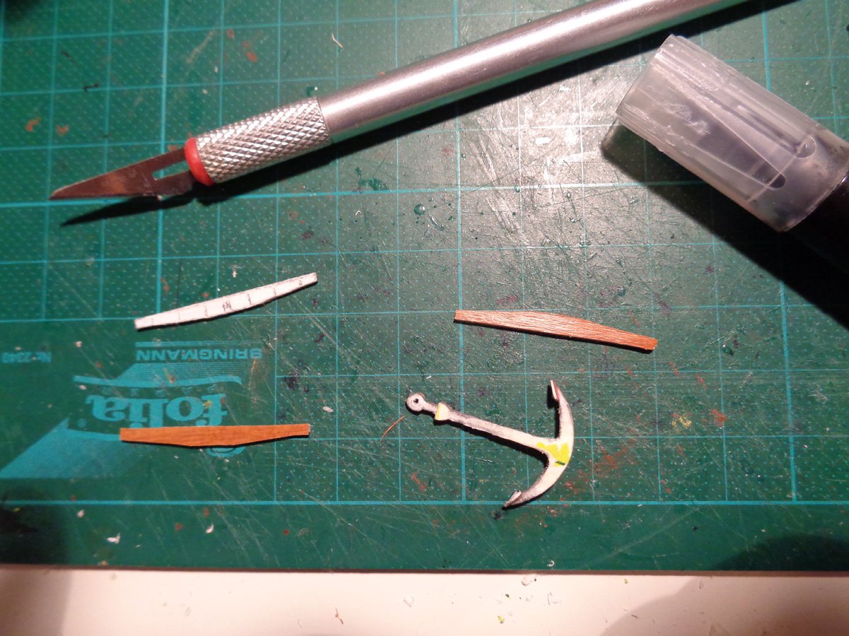
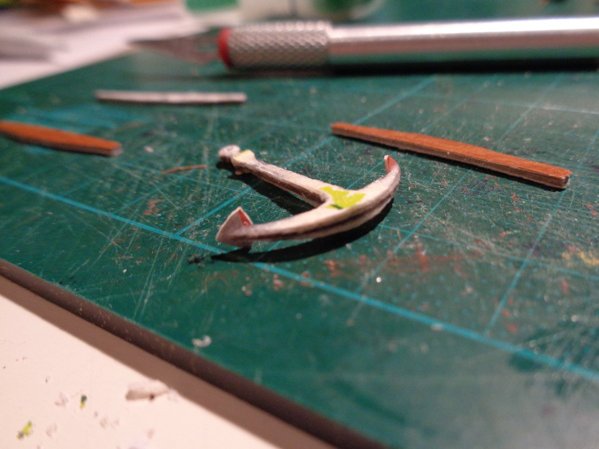
And here some images of the second one and the correction of the first one:
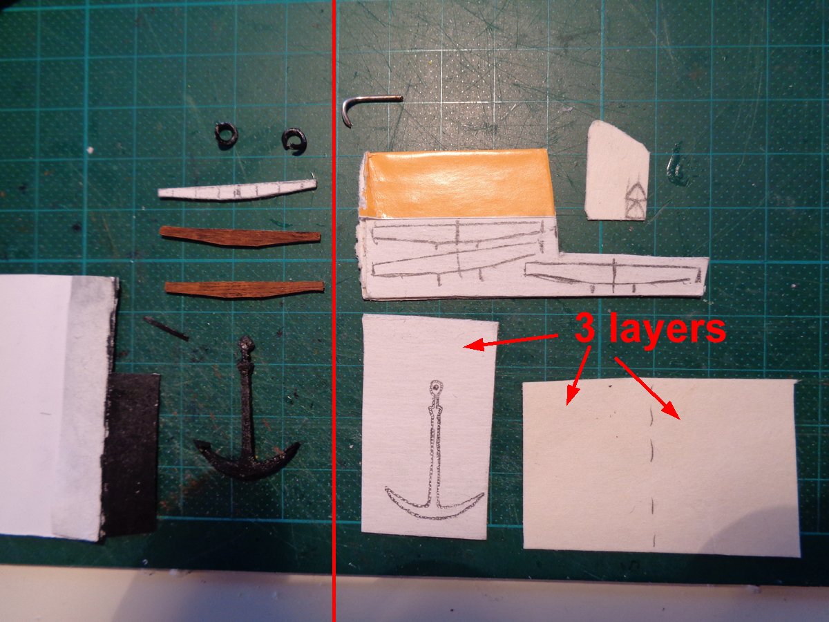
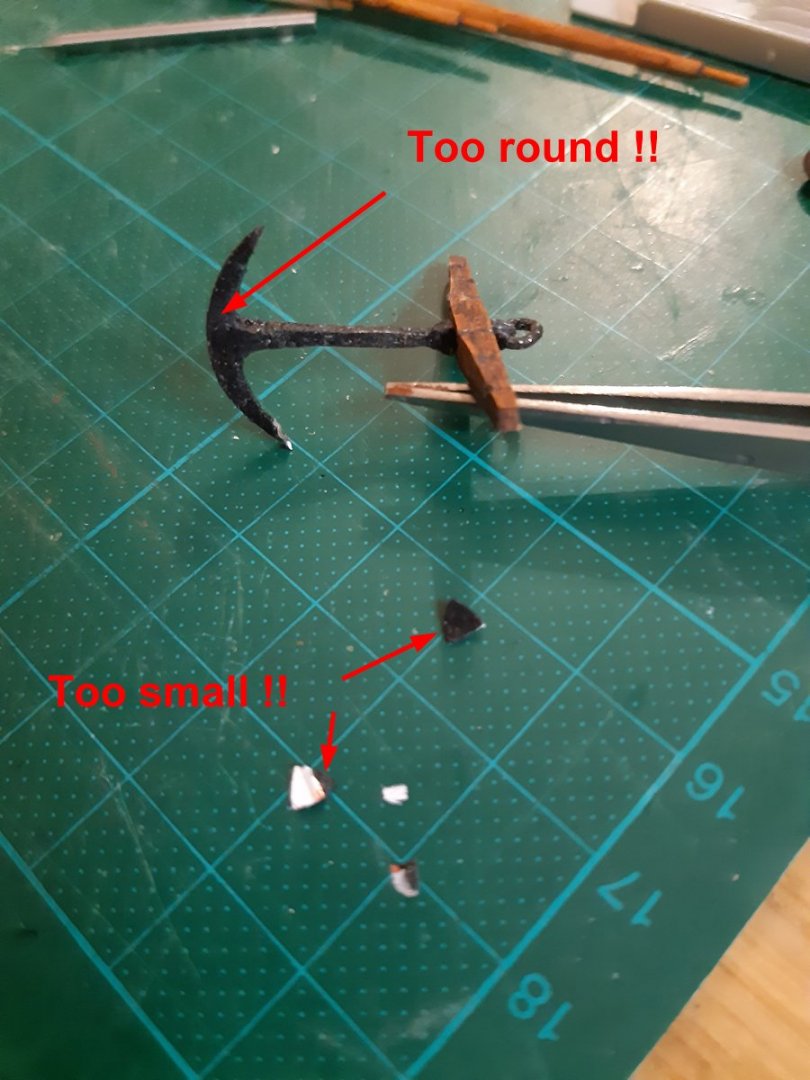
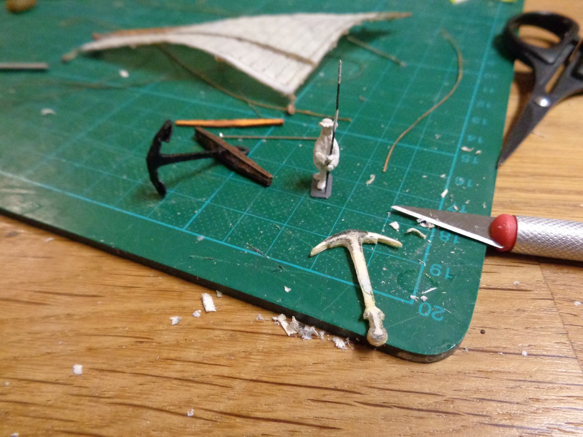
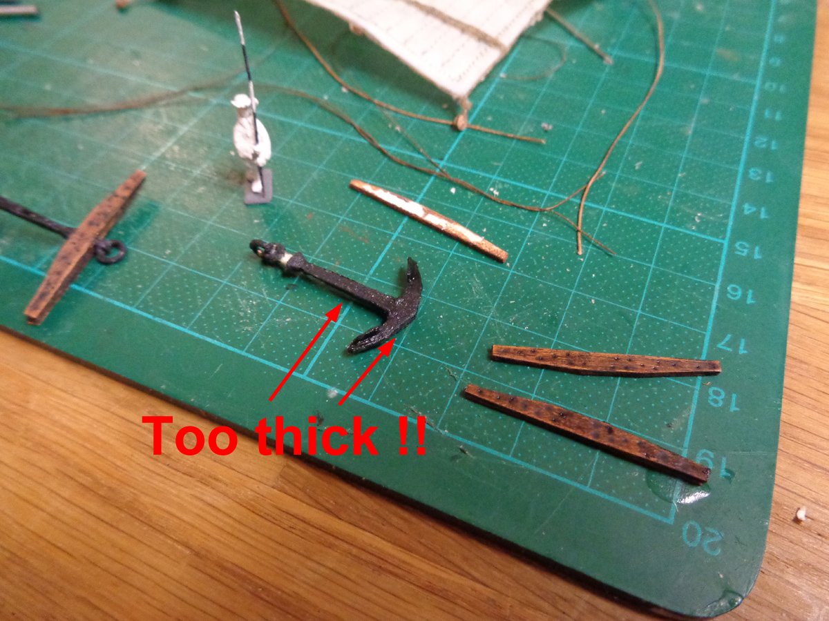
I used a lot of CA glue to strengthen the soft card parts and shape them into the form with a scalpel, similar to shaping a piece of wood. Then I painted the anchor with some black water-proved marker. Interestingly, on the shiny glue-soaked card, it gave the anchor a metallic luster.
The anchor stock was made from card with the self-adhesive foil and altered with oil paints. I removed the metal bands, following Ab's advice.
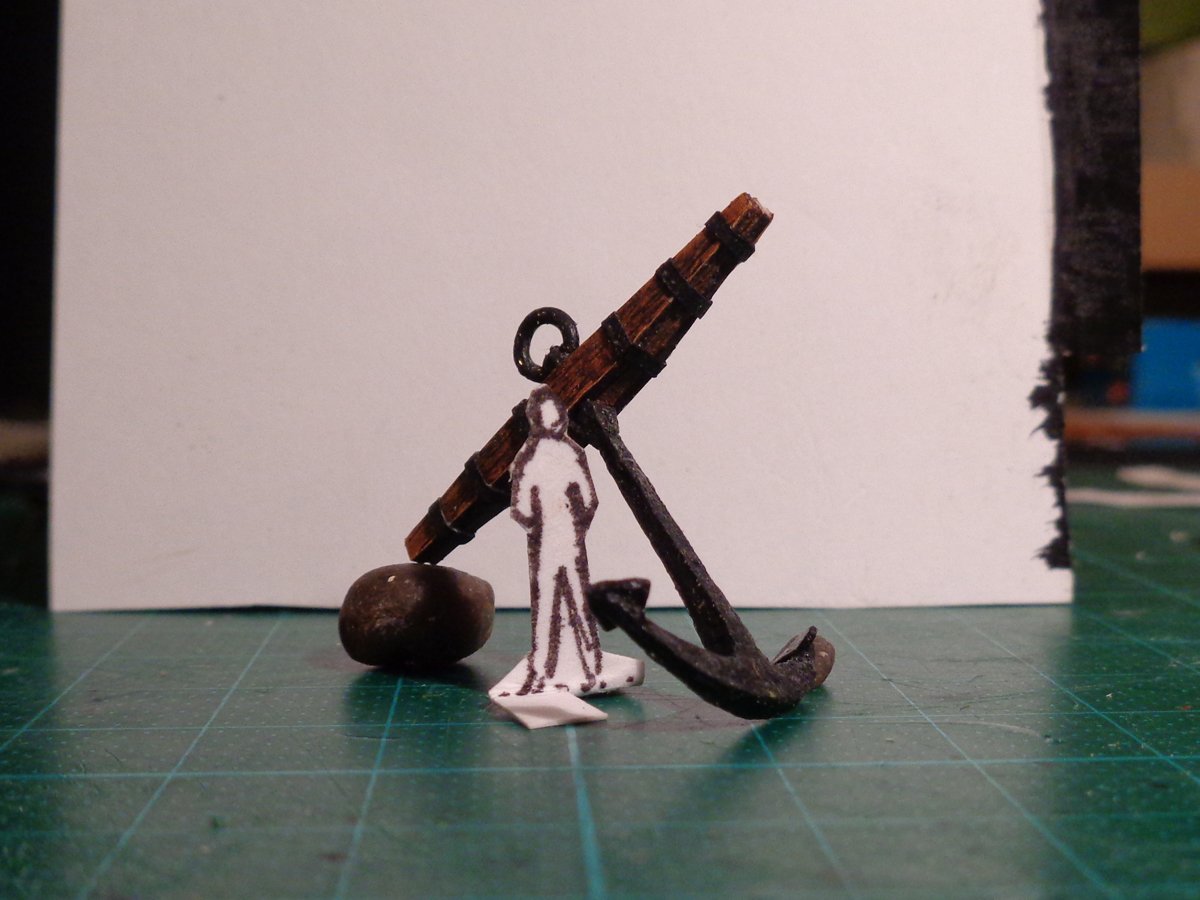
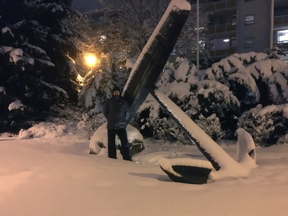
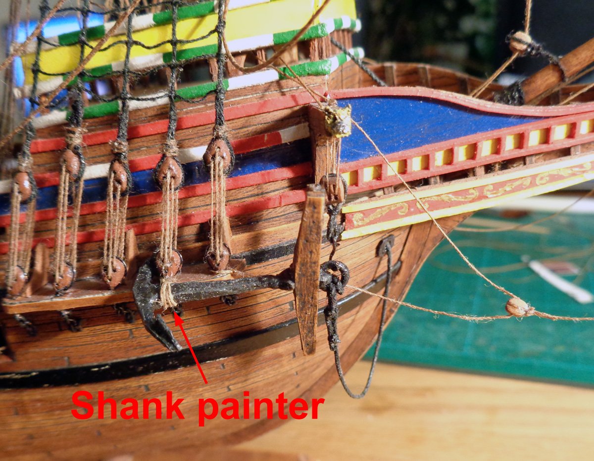
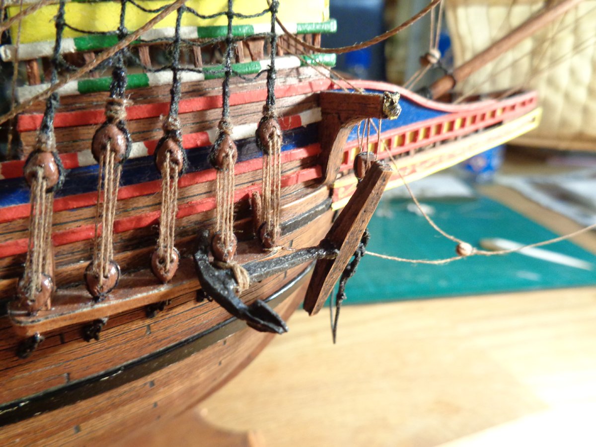
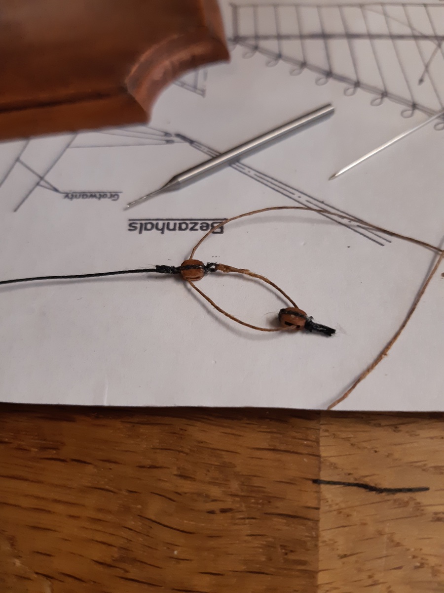
Then I tried to figure out the rigging of an anchor at the cathead. There is surprisingly little material on that topic. But I found some images here on the forum and in the book of Wolfram zu Mondfeld.
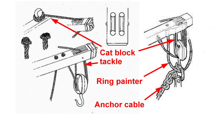
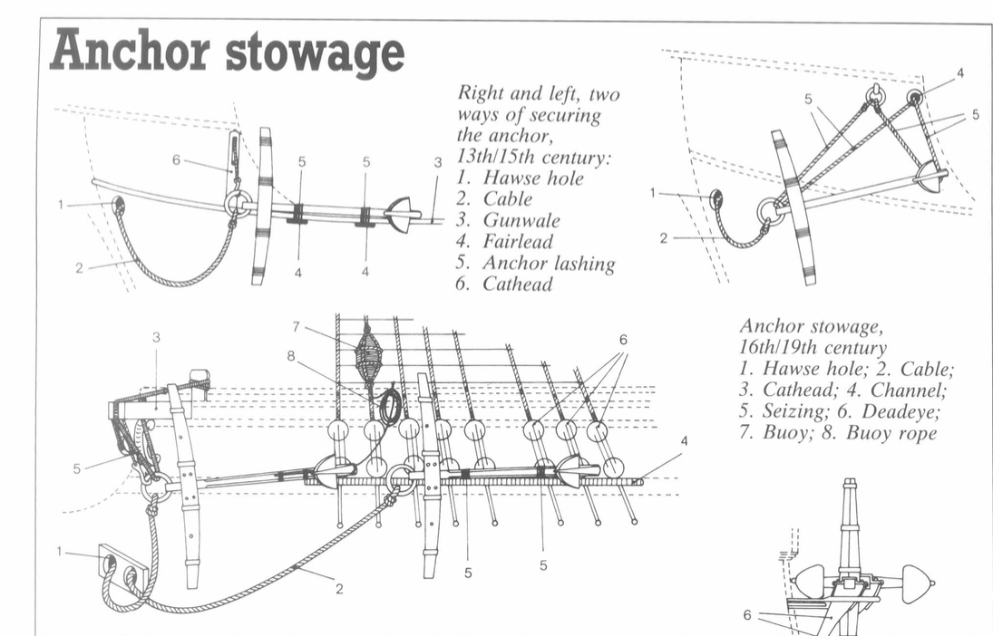
The question that went through my mind was how to make the ring-painter or cathead stopper, or as it is called in zu Mondfeld's "Historic ship model", under No. 5 "Seizing" or "Anchor lashing". I did not want to let it run via the cathead back to the deck, as my cathead did not have the required grove on it, nor a guide for the rope attached to the side (sheave for cathead stopper), as is the case in later catheads. Since no one really knows and I thought the Mayflower is in a time of transition to a more "save" storage of the anchor, I decided to go with what's practical and let it run from the anchor-ring straight back to the deck and the nearest belaying point, similar to the description in Mondfeld's Anchor stowage for ships of the 13/15th century, as if the builder did not yet had the idea of letting that rope go back via the cathead so it would keep the anchor a bit farther away from the hull. However, it starts from the cathead with a rope that has a big knot on the upper part, like in the first image I found here on the forum. Here some pics of the process and the last two pictures show my solution to the anchor lashing/ring-painter.
So much for now, next post about the sails and flags. The Mayflower is almost finished, I am just attaching the rope coils on the deck. So I will finish it in the next few days.
Kind regards,
Radek
- mhkash, mtaylor, GrandpaPhil and 2 others
-
5
-
10 hours ago, mhkash said:
Hello Radek
Really Excellent build , and the grating is Super .. When will you start your next model .. do you have any idea yet
Thanks!
I struggled with the grating a bit, was not easy to cut out every single hole with the scalpel...😅
My next build is in progress, it will be the fictive Spanish galleon "Neptune" from the movie "Pirates" by Roman Polanski.
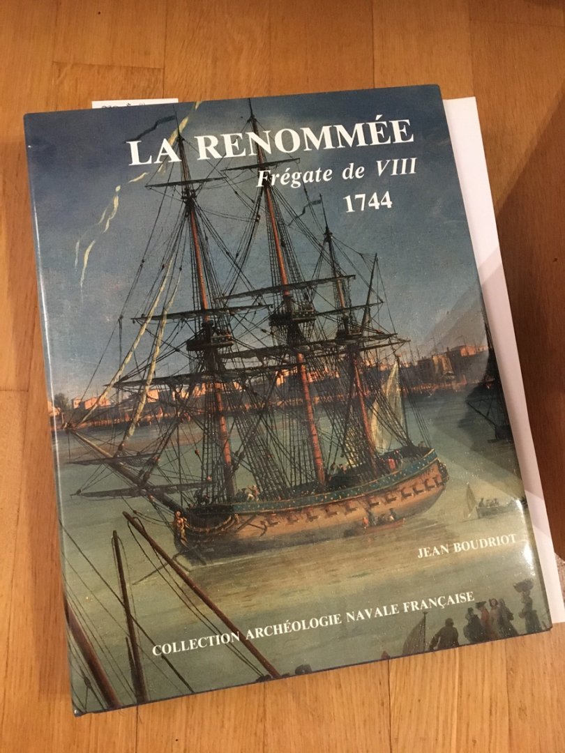
And when I get bored with that, I have started to look into my LaRenommée Monograph...
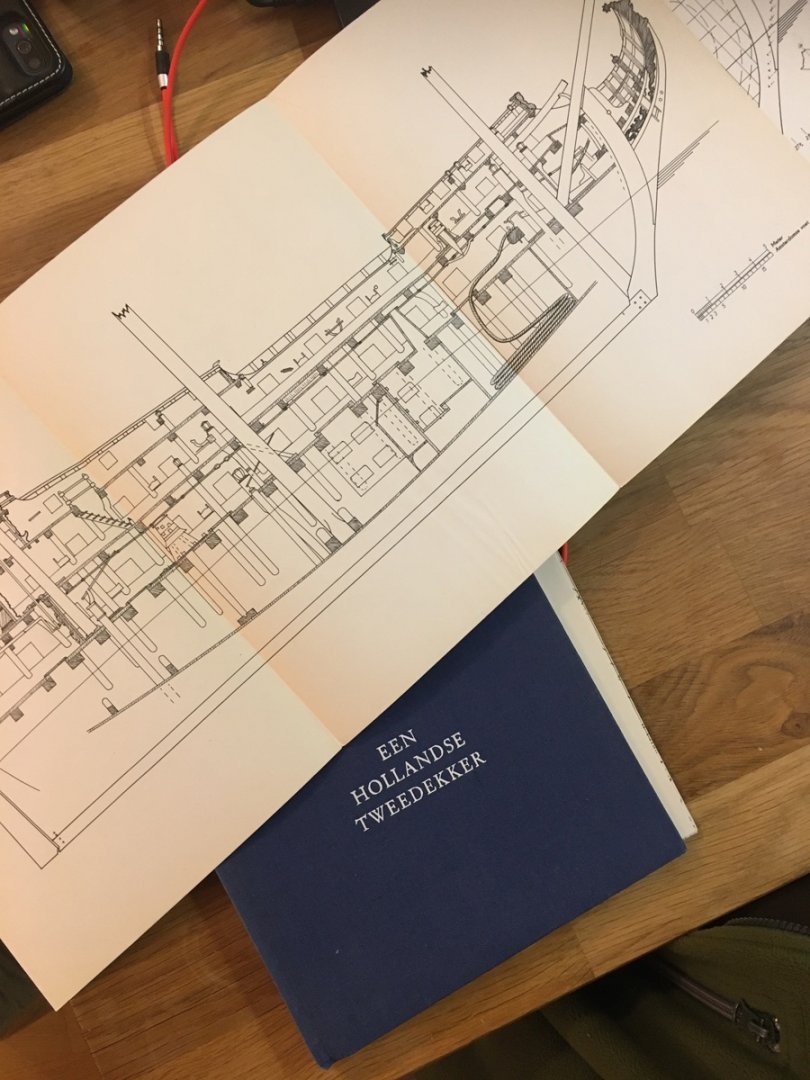
Also, I have to fix two of my old card models, a carrack and the Bounty (sorry no pictures at the moment because both models are in the attic)....So lot's to do. And then there is the book "Een Hollandse Tweedekker" that is on the list as well.
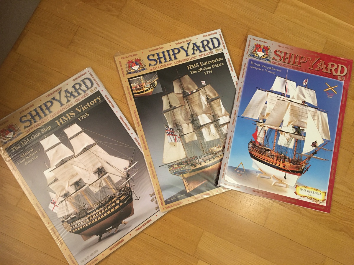
As if that would not be enough, my brother bought me this year some Shipyard paper models of the Bellona, the Enterprize and the Victory...😅😅
But first, I need to finish the voyage of the pilgrims in this 400 year anniversary year 2020...
Then I'll practice installing light in the model as well as sculpturing some 3D-figurines on the Neptune. Then I guess it will be time for the Tweedekker and in between my Renommée project, which I will introduce here once I am sure what I am doing.
But I have to balance real life with hobby, and apart from ship modeling I like to climb, play basketball, practice my rusty piano skills and of course manage with my full-time job! At least my studies are close to an end, looks like next spring I can finally defend my PhD-thesis...😳
So much for now. Back to finishing the Union Jack for the Mayflower! 😉
-Radek
-
9 hours ago, amateur said:
The size an number of the gratings is based on the contemporaneous model. So, why should you change?
Gratings were used for all ships with a lower gundeck. Real warships had even gratings over the full length of the ship.Or do you mean the number of strips used for the gartings (the size of the holes. Than you should try to follow the rul that the size of the holws is slightly smaller than the with of a foot (ie around 10 cm). The museum-model has holes slightly wider than that, but not as wide as yours.
Jan
Thank you for the clarification, Jan. Always something to learn for beginners such as me...😊
-Radek
-
Hi Tomek!
Nice to see your build here! Although I am a scratch-build modeler, should your project make it to the shelf, count me in a s a customer! :)
-Radek
-
-
-
-
Hi!
I wish I could do some wooden model even like your first one!Nice work on the hull so far! My first ever wooden ship, the Elbing Cog based on paper-model plans from the polish company Mały Modelarz was also from balsa.I replaced the card with it because I wanted to do something from wood but don’t have the tools or space for it. I worked mainly with a scalpel and some CA glue and painted it with some sort of wood-finish...You can find some photos of it in the gallery.
But I returned to card and paper because it is cheaper and does not require so may tools...Currently I finish my Mayflower, which I started
10 year ago!😱
How do you color your model? The deck looks very authentic! One point though: The grating seems a bit big. And I like the open gun ports.
Rgds,
Radek
-
Hi everyone!
Thank you Tony!
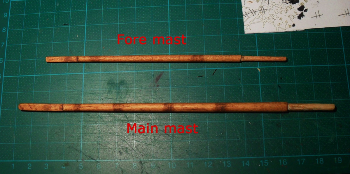
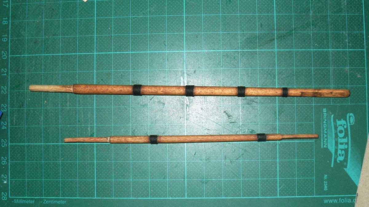
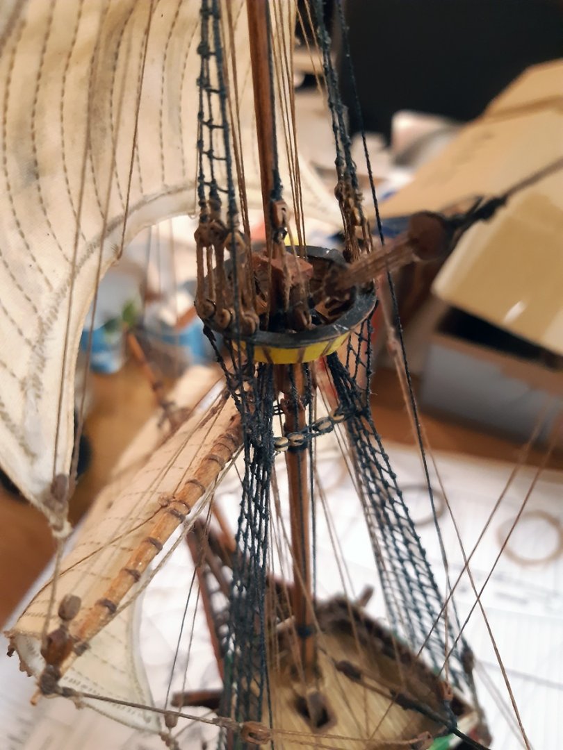
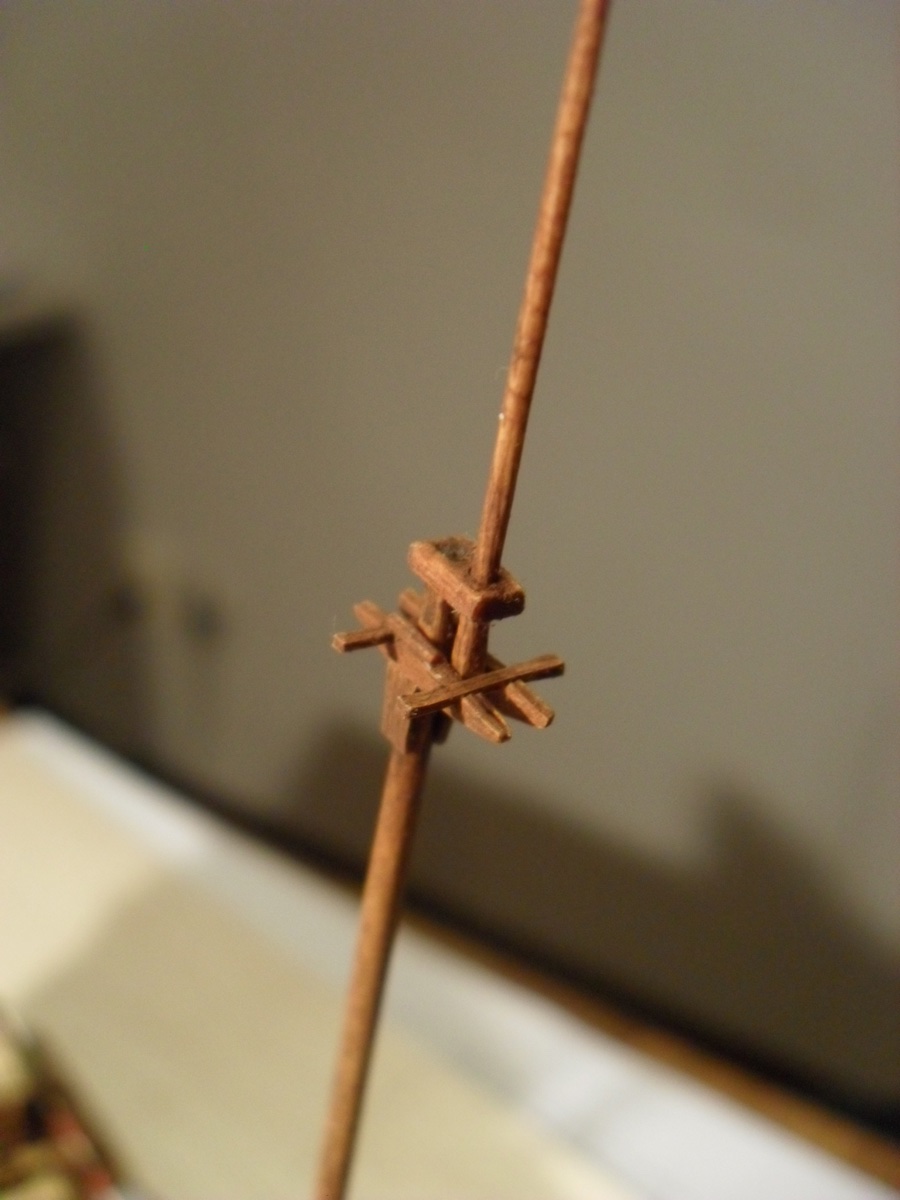
At this stage I finished the rigging of the ship, only the flags, the rope coils on the decks and the anchors are missing. I will post some pictures about the current state soon. But first let me show my work on the masts....
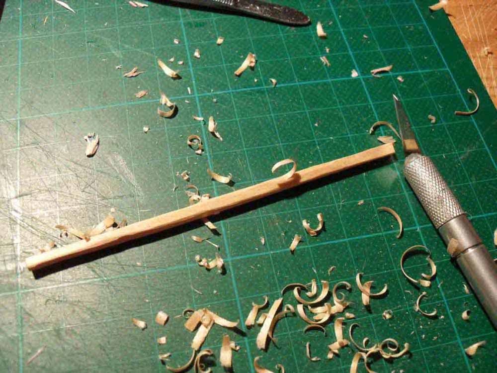
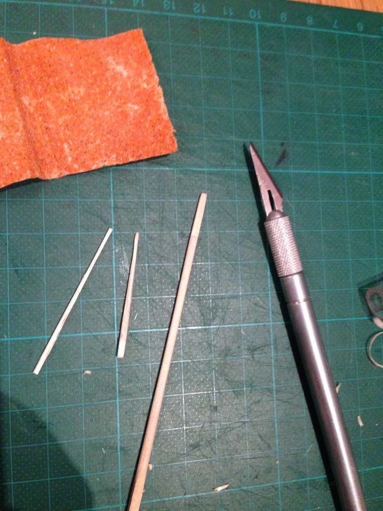
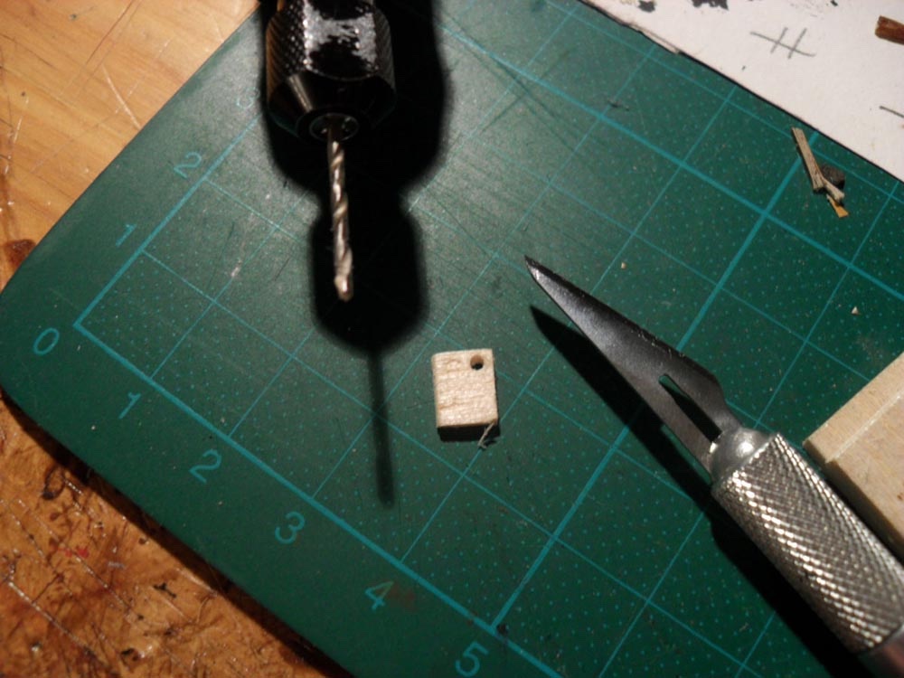
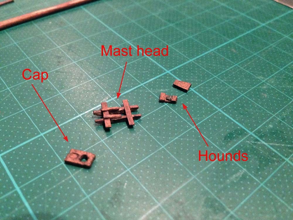
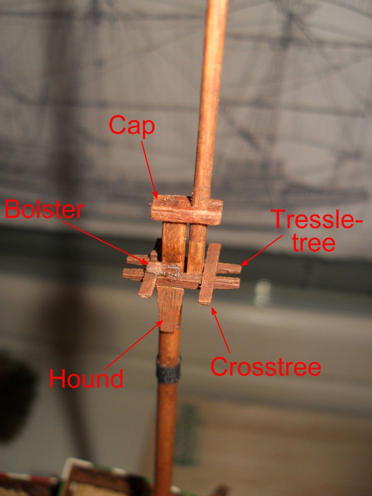
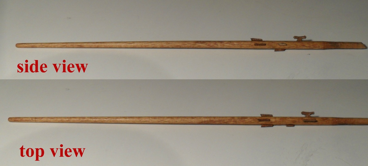
I made them from wood. Just some round wooden staff from the hardware store. I do not know what type of wood that is. But it was easy to cut it roughly in shape with the scalpel and then sand it down to the right size.
Then I painted it with the oil paints 'Burned Umber' and 'Burned Sienna' and altered them a bit with 'Black' around the places where the woolding is attached.
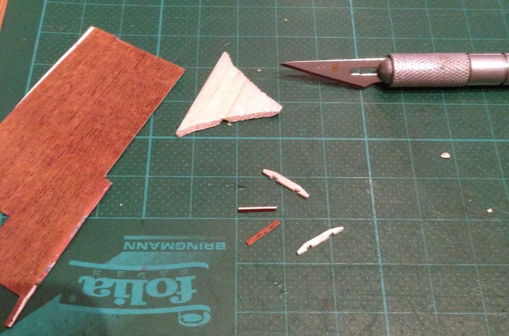
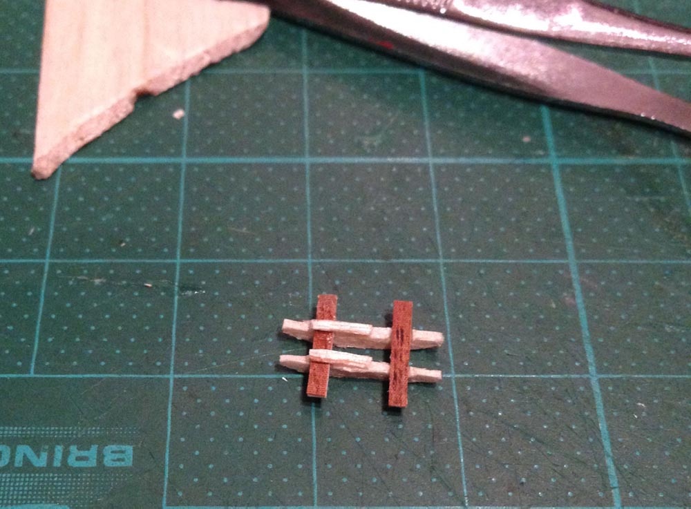
The trestle tree was made from a mix of cardboard, the self adhesive foil and some balsa wood....

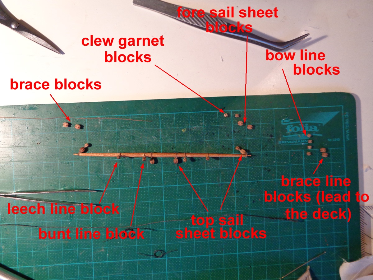
The yards were made in a similar way like the masts. First a bit carving with the scalpel and then sanding it down...
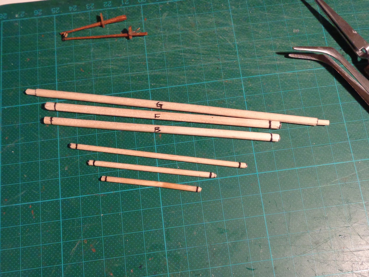
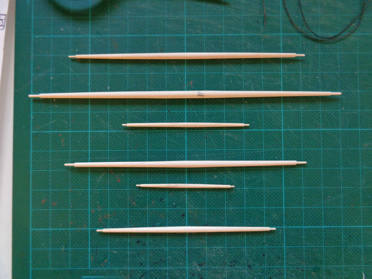
Later I painted again with the same brown oil paints as mentioned and rigged the yards, before attaching the sail and onto the model.
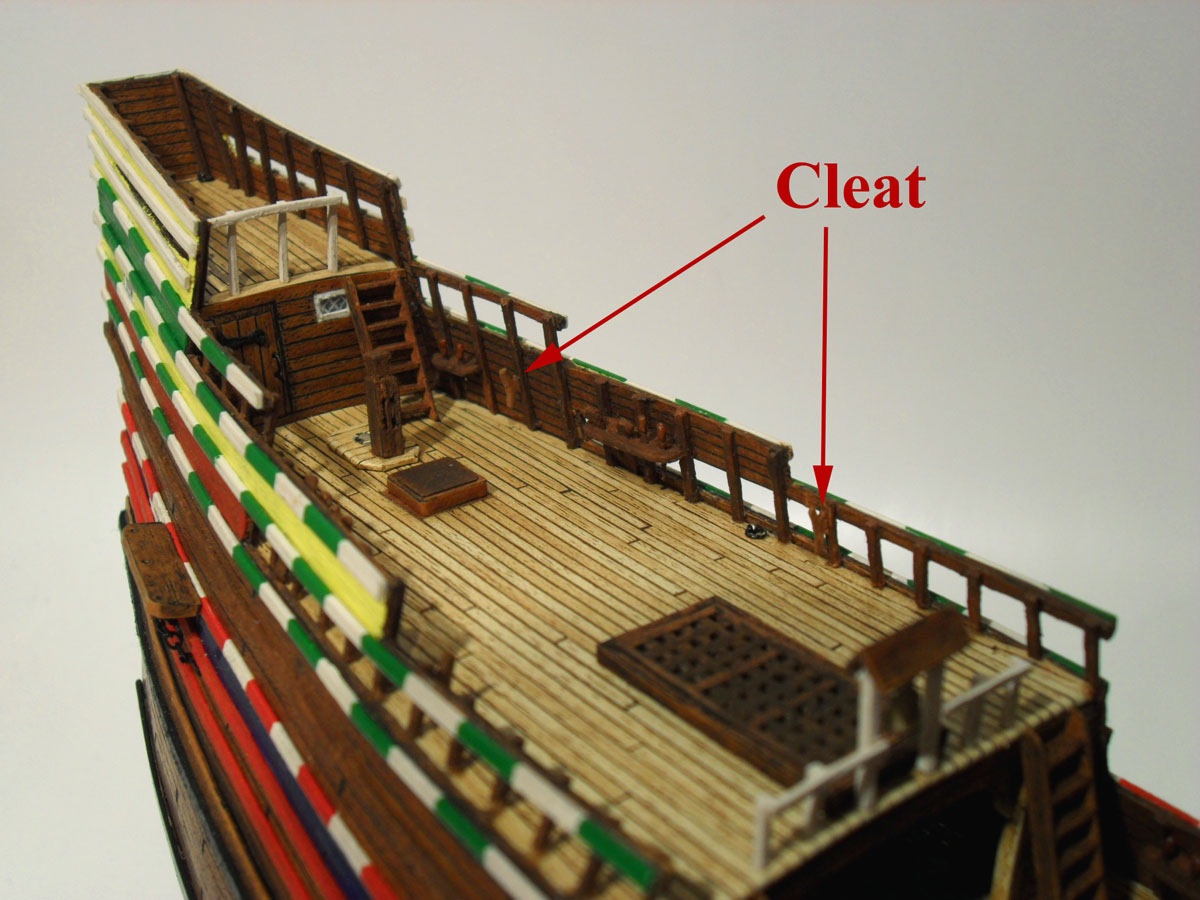
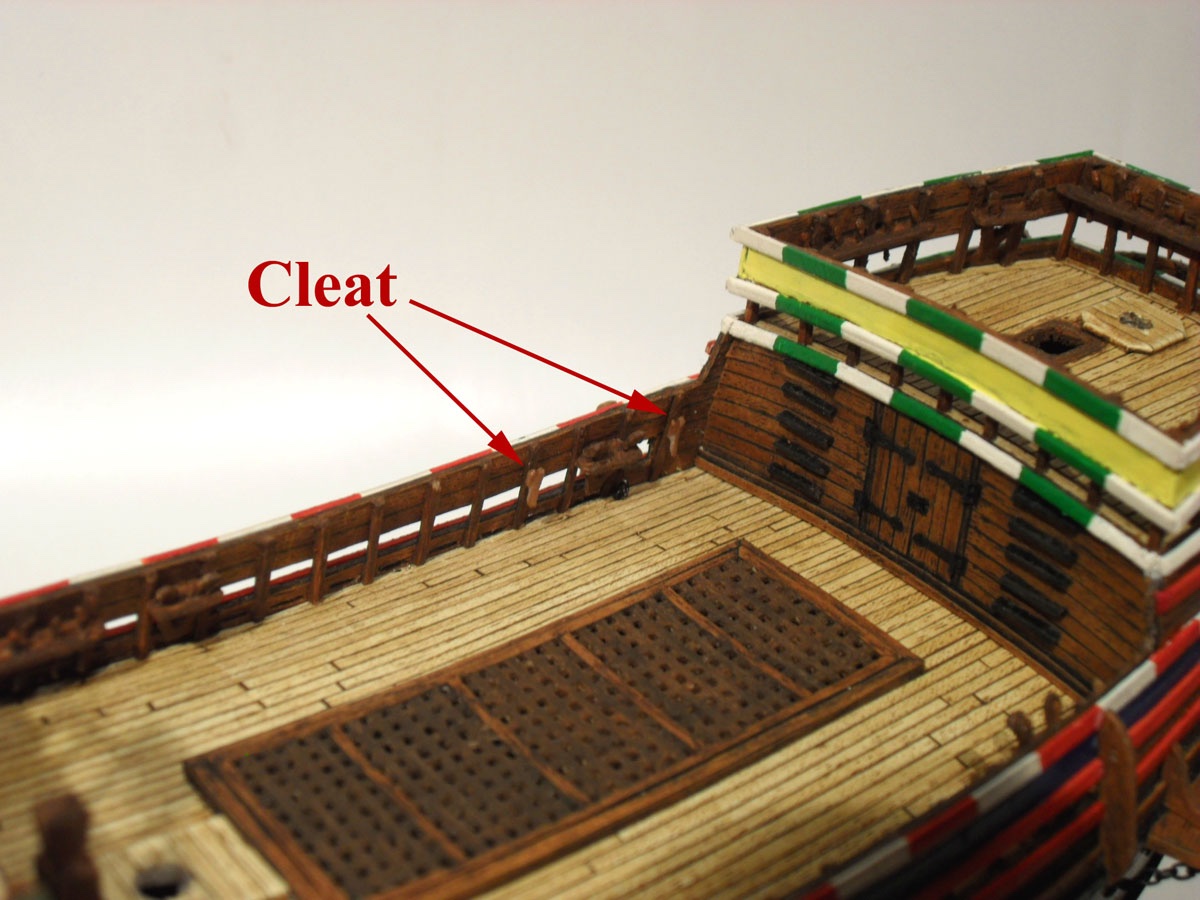
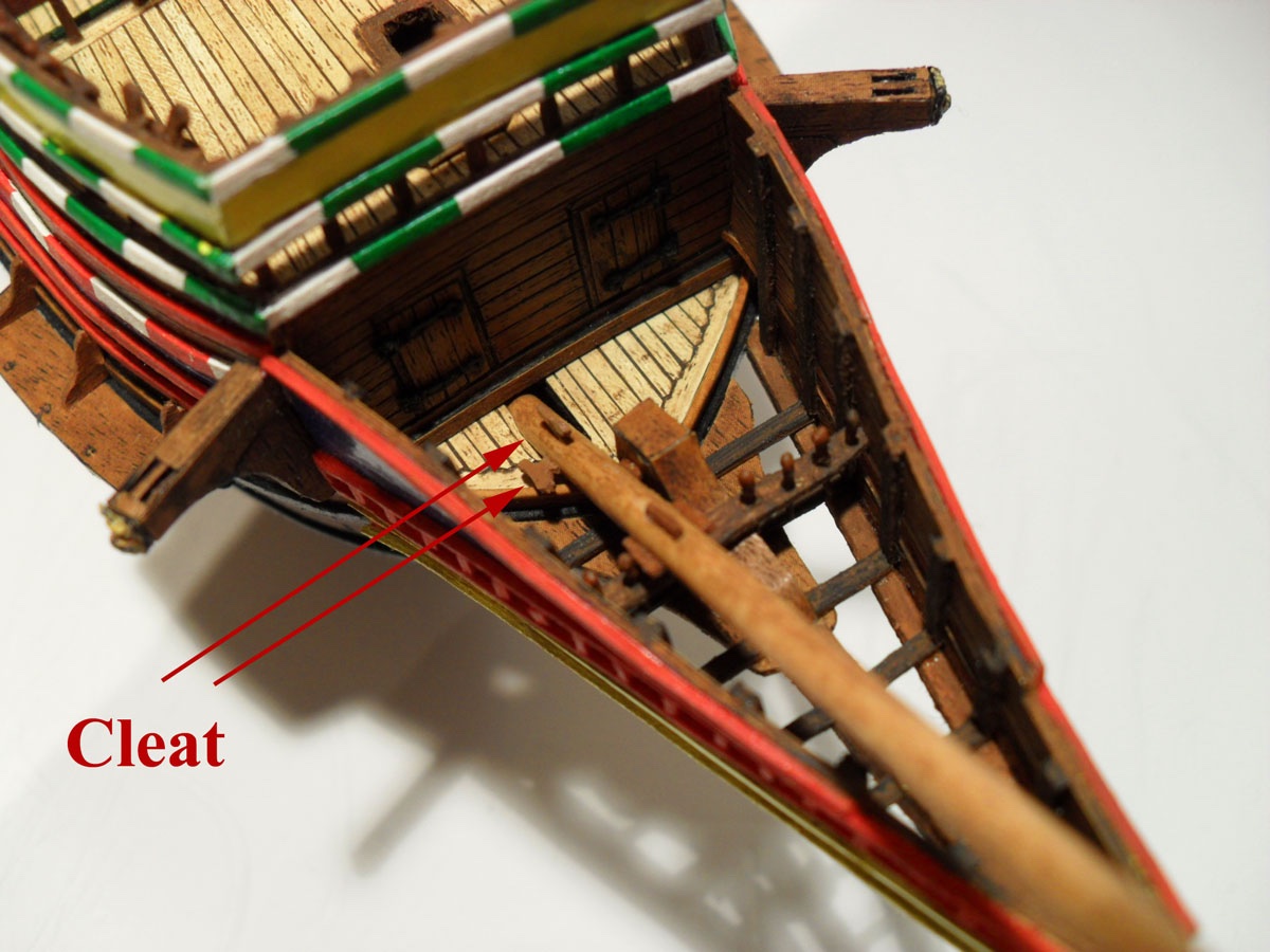
Small deck fittings like the cleats were made from cardboard painted with either Humbold enamel or a brown paint marker.
At that state I had to make a break to my modelling and wrap up the Mayflower...just to take it out some 5 years later...
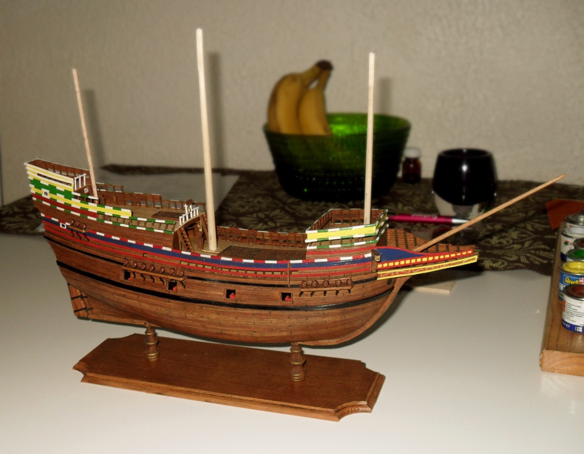
Right now the model is in the following state:


My apologies for the bad quality of these last three pictures, I have to work out my (not anymore so new) snapshot camera....
So much for now.
Rgds,
Radek
-
Rigging compromises...
Hi everyone!
The anniversary of the landing of the pilgrims is here... Today, 9th of November 400 years ago the Mayflower arrived in the new continent. Sadly I did not manage to finish my Mayflower in time, my pilgrims are a bit late, I guess...
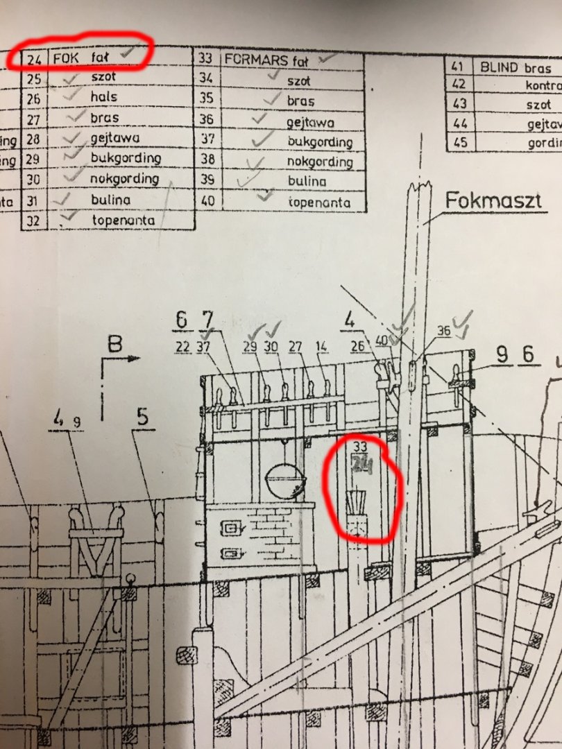
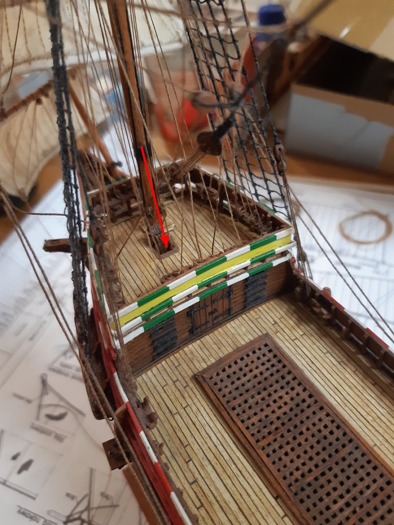
But I had now time to continue with my model and encountered some rigging problems. For one I mentioned already that the halyard for the fore top sail and the topsail are missing in the plans. I found the answer to the rigging in Anderson's "Seventeenth Century Rigging" (Thank you Ab!) , where he describes it as being mounted in the top in three parts.
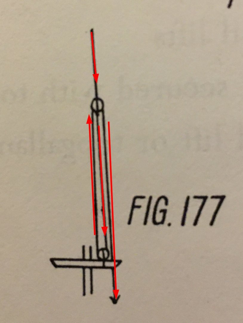
He also describes the halyard to be attached at the deck to the sides or the rail. However, in the plans it is attached at the same position as the fore sail halyard inside the fore castle.
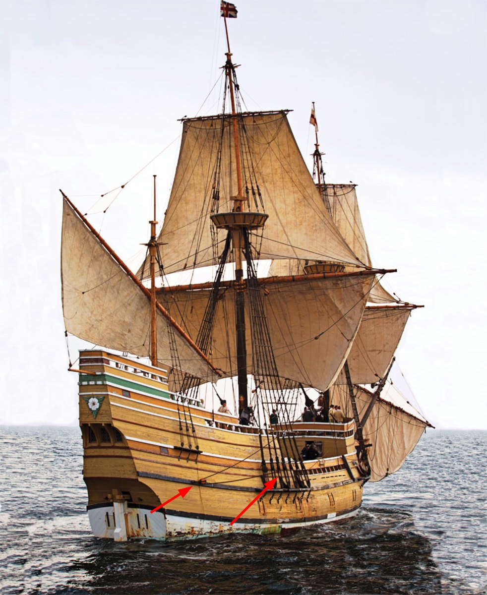
In comparison, the Mayflower II has a top sail halyard that is according to Anderson from the 1700s onward, so too young for my model. It can be seen in action in some of the restoration videos and for instance on this picture:
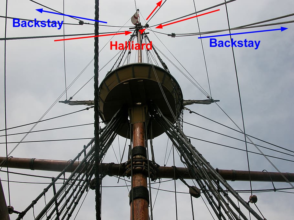
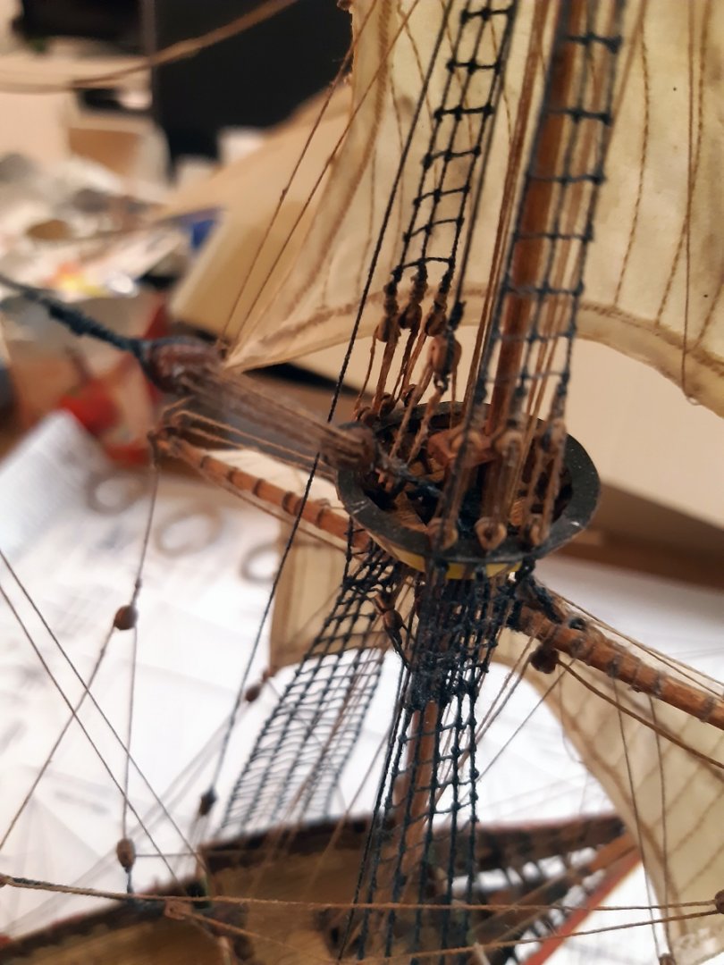
I decided to make a compromise between Anderson and the plan and on the ship it looks rather clumsy in 1:100...

Another rigging problem occurred when looking at the plans for the main sail sheets. The plan shows the attachment to the side of the ship as follows.
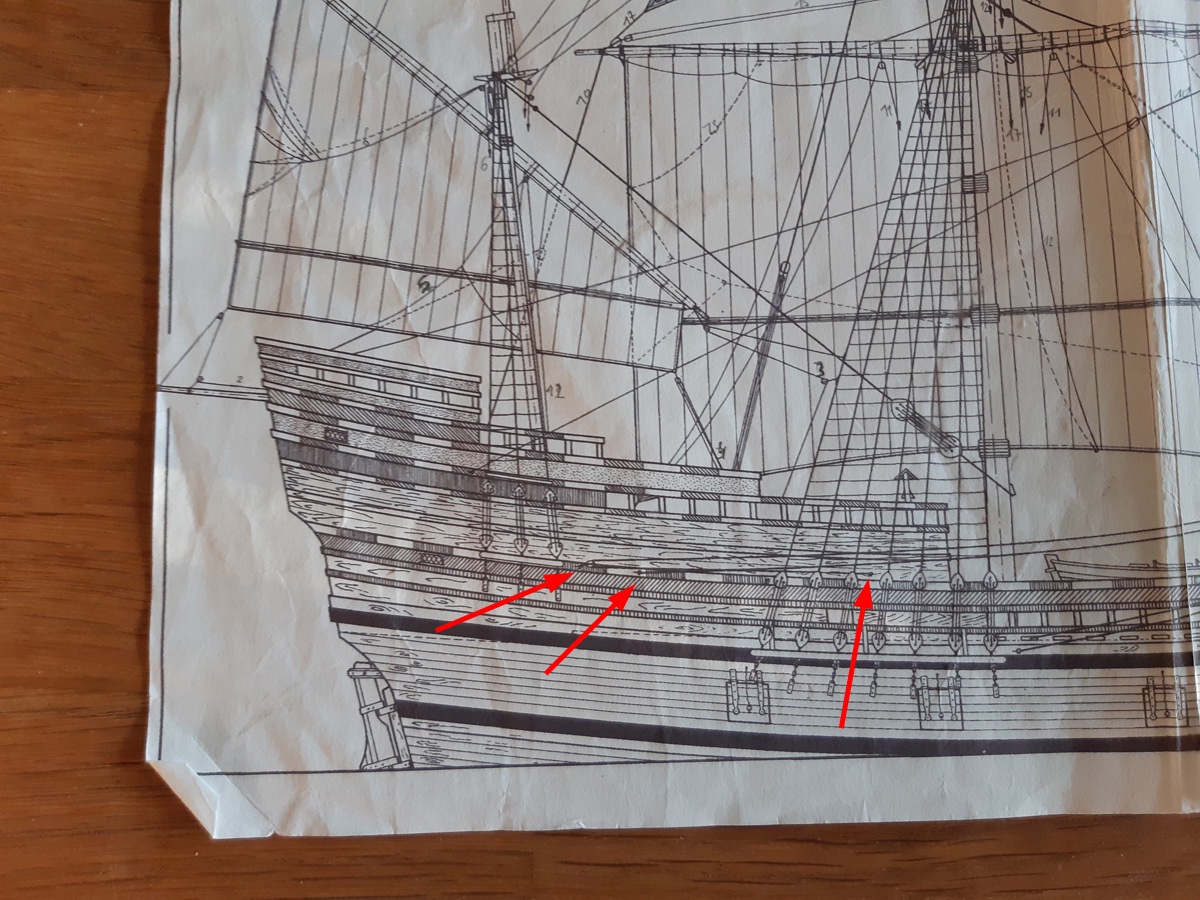
The Mayflower II seems to have a completely different arrangement and it also appears as if the main sheet and the main tack would be one and the same line....confusing....😓

Anderson on the other hand describes the attachment as being during that era (early to mid 1600s) not typically with an extra block on the side (but possible) and typically starting from a ring-bolt on the wale, leading to the block at the clew of the sail and back to sheave in the bulwark or to a block on another ring-bolt and then to a hole in the side. This second block should be above its standing part. The sheet should also never foul guns or chain plates. I did the following on the model:
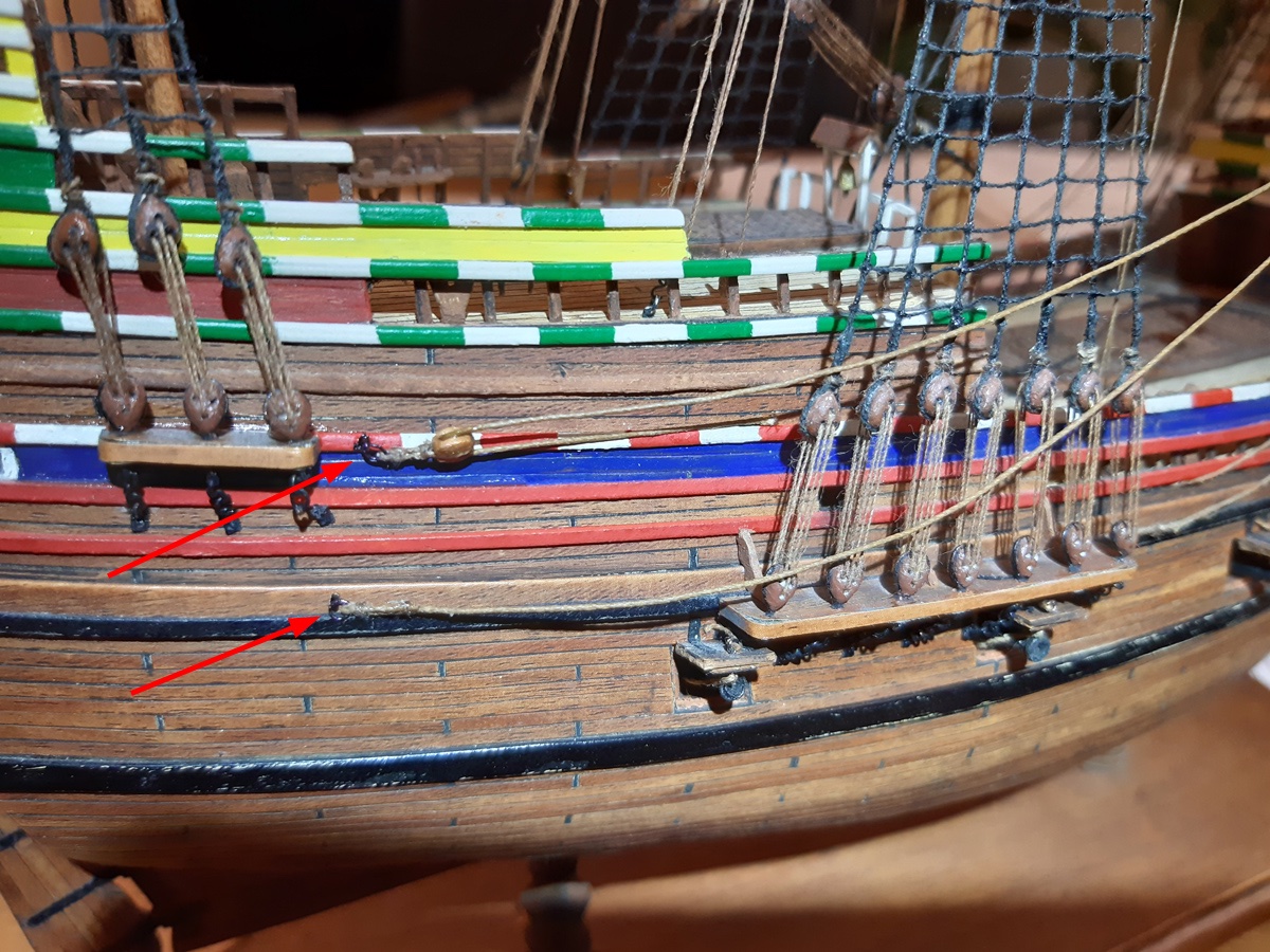
A similar and more confusing problem appeared with the main sail braces, but more on that in the next post. Here some pictures of the progress so far with the last picture being the most up-to-date state of my Mayflower. Sorry for the not so good quality of the pictures.

See you soon!
-Radek
- GrandpaPhil, mtaylor, daHeld73 and 2 others
-
5
-
-
Hi everyone,
again, my sincere apologies for having that build on hold. As only a part-time PhD student it is not easy to focus on what's important. But the good news is that I have only one talk to prepare for my studies, which leaves me with more time to get the Mayflower back to the shipyard and finish still this year.
Otherwise I hope all of you are well in this difficult times of the pandemic.
All the best and see you very soon with some updates here!
-Radek
-
Hi there,
Ab, If you are notoriously lazy, what am I? ...Considering it takes me 10 years to finish a small vessel like the Mayflower... 😄
And the oversized stitches made me laugh heartily, because it is so true, Ab! I just imagined a sailmaker handling an oversized needle..!😂 But I am glad you like it, and I agree, they add something authentic to it. I also like the idea of drawing the seam stitches and will try that in my next model.
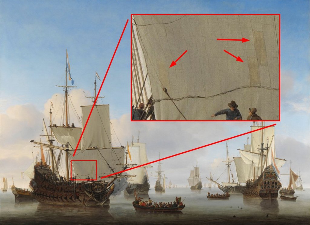
21 hours ago, druxey said:Patches can look darker if light is coming through from behind them, Radek.
Thank you for the information druxey. I was not thinking about that.
But in the case of this painting, the patches are really darker than the sail cloth. The light seems to come rather from high up and almost straight above the ship from the left. And look at the main topsail patches:
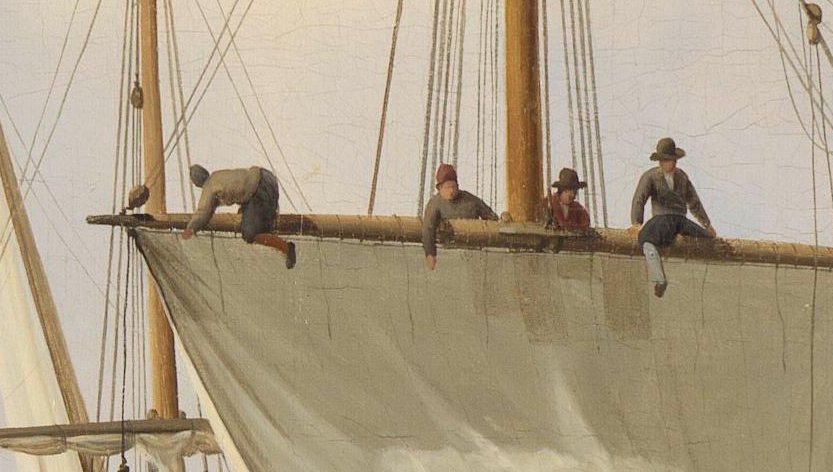
Maybe, they were made from cloth during the voyage and it got dirty while it was stored? Or it was simply a slightly darker cloth...
As for the silk span in Europe, I've found only that brodak.com seller, which apparently sells his product also in some selected european hobby shops. Ab, I've sent you an email. But I am not sure if that is the same stuff.
-Radek
-
Hi,
My method of sails is quite 'amateur' by stitching them, simply for the relaxing joy of stitching and I like the structure of the wrinkled cloth in the end.
But apart from that, tea for dyeing - the more tea the darker - and I use Lord Nelson's black tea...
") Then I shape them with the clear varnish as described here. Then I use diluted oil paint (diluted with turpentine) to alter - the less the better - and the thinner the better. I guess acrylic paint is good too and you can use some alcohol, if it does not dilute the starch as much as water..? I also noticed that just a bit of some dirty water does the trick also. After all, the sail cloth for our models is just like a piece of fabric so why not behave like little children again and get a little bit messy?
Then I shape them with the clear varnish as described here. Then I use diluted oil paint (diluted with turpentine) to alter - the less the better - and the thinner the better. I guess acrylic paint is good too and you can use some alcohol, if it does not dilute the starch as much as water..? I also noticed that just a bit of some dirty water does the trick also. After all, the sail cloth for our models is just like a piece of fabric so why not behave like little children again and get a little bit messy? 
Druxey, I alter my sails after shaping...😊
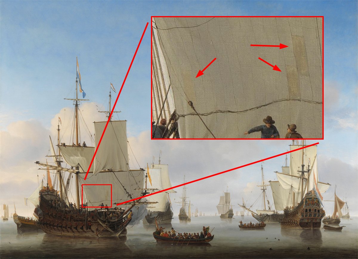
On a bit more professional note: Patches do not necessarily have to be brighter than the rest of the sail. Look what detail I've found on a Willem van de Velde II painting (you know it probably already):
Maybe just paint/draw some different color patches on the sail? Maybe that can be accomplished with white paint, too?
Here's an example of my first try to imitate some patches on the foresail of my Mayflower model (I might try some other color next time) 😅:
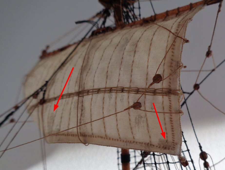
Just some suggestions. Working on finishing my sails right now and hope to posting some progress on my own build soon.
Thanks Ab!
-Radek
- Benjamin Raule, Piet and mtaylor
-
3
-
Hi Ab!
Nice pictures again from your son! I just changed the desktop background today at work to another one of your splendid masterpieces ("Pinas in de mist")! Van de Velde himself and his son would get jealous! ;)
The models look very real on the pictures. One word of constructive criticism if you allow me: Make the sails more dirty...maybe not as dirty as I exaggerated in my Mayflower model, but they seem (to me) too clean on the pictures...Maybe that can be done in photoshop as well? That way you keep the real models clean... :)
Great job on the Speel-jacht!
Seeing your projects piling up inspires me to continue with my own ones.Thanks!
Looking forward to seeing more!
-Radek
-
Hi there!
Thank you for the informative lessons (of the Dutch as well as your ship building career)! The model comes along nicely! A very interesting design, too. Reminds me of an oversized rowing boat. Looking forward to see more.
But until then stay save with that heat scorching the lands in Europe! Here in Helsinki we have enjoyable "Finnish summer temperatures" of around 20 degrees which feel even colder due to the sea wind - just ideal to work on my thesis (and unfortunately not on my Mayflower...).
Rgds,
Radek


Neptune by RdK - Scale 1:100 - CARD - Spanish pirate galleon from Roman Polanski's movie "Pirates"
in - Build logs for subjects built 1501 - 1750
Posted · Edited by RdK
change order of images
Hi everyone!
This is my next build after finishing The Mayflower, which you can see in the Gallery here.
I started this build already a while ago, back in 2012. Life circumstances caused me to give it a break in an early stage. However, with my life in order (more or less) and no other project going on (I put my Renommee idea on hold for now and next in line is then anyway the Hollandsee Zweedekker).
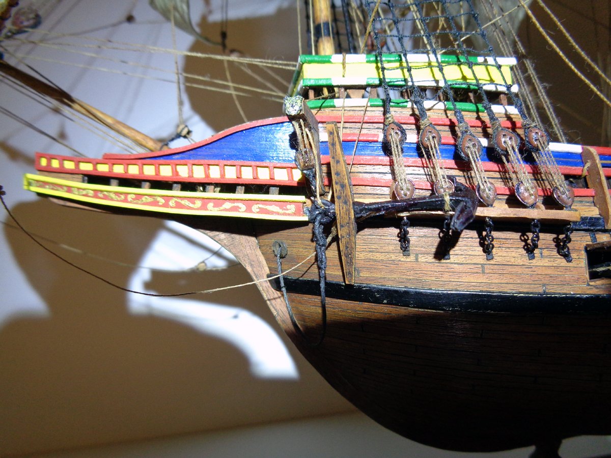
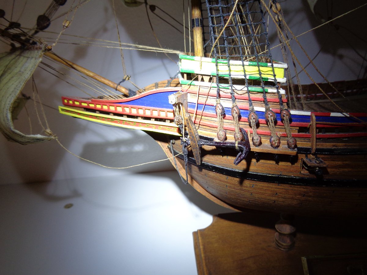
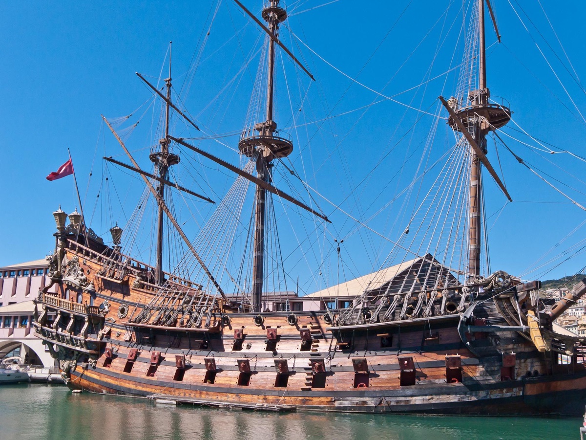
The ship is the replica of a Spanish treasure galleon, ´The Neptune´ for the 1984 movie "Pirates" by Roman Polanski.
This built is an excursion into LED lights and model clay sculpturing. Ever since I saw this replica on the internet, I always wanted to build it, mainly due to the rich decoration of the stern.
I have never really tried to sculpture such details from the clay, my only experience with it being the deadeyes, catheads and a small shipwright when I made the Mayflower. But you'll never know if you are good at something (or not) if you do not try! So here I go...
Another experiment in this built is the LED lights, that flicker like candles. If I am not mistaken, dantist905's Soleil Royale was the first model I've seen with LEDs like that. So here I try to make my own version of it, partly successful so far.
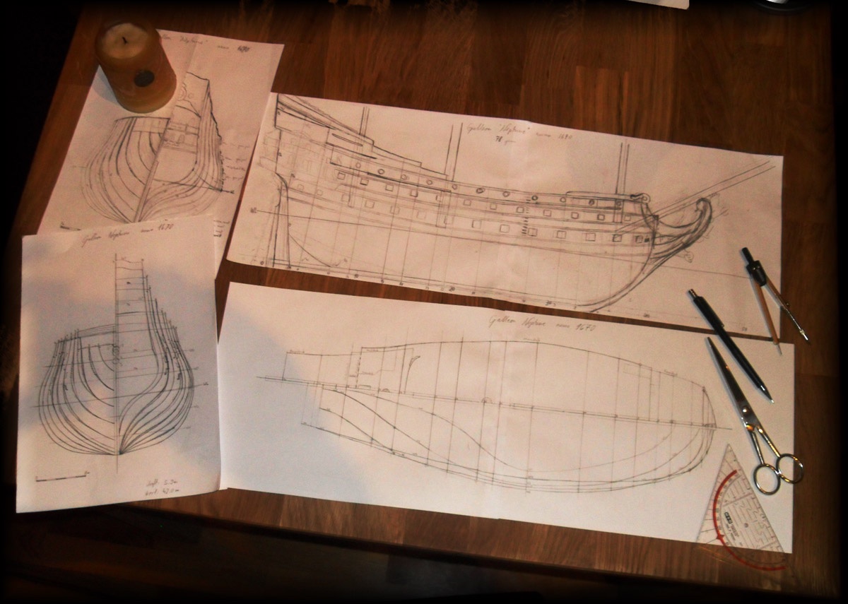
Since this is a fictive ship, a prop (theatrical property), it is not historically accurate and gives me a bit of creative space... But the drawback of it is that I have no plans and background on this ship so I have to make it up, including the history of the ship. I created a story around this ship over at papermodelers.com but it develops based on the comments there and what happens during the build. Without previous knowledge I set the construction of my version into 1670 and later I saw a plate from the interior of the replica that has the fictive date of 1672 on it, so I was not that far away with my interpretation of the stem and stern...")
The only other model of this replica I know of was beautifully made by a Russian modeler named Vitaly Maslov.
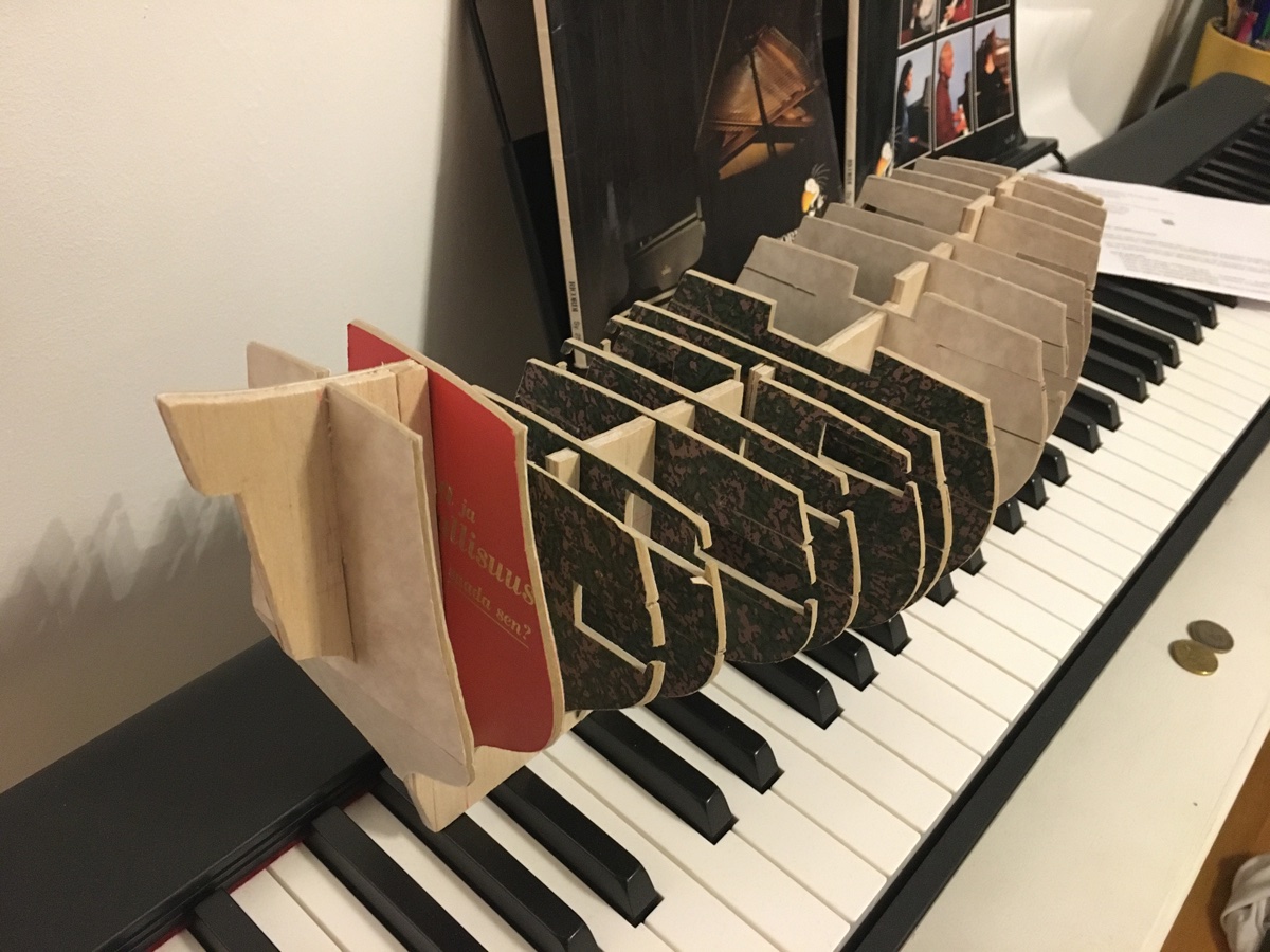
My version is not an exact 1:1 copy of the replica that is now in the port of Genoa in Italy, but I try to make some research on Spanish galleons of that era and whatever does not fit into the historical facts, becomes part of my fictive story.") Also, my version is made again from card and paper mainly.
Also, my version is made again from card and paper mainly.
Now I do not know if you guys here would be interested in the fictive story. I could only copy it here from the papermodelers-forum as it kind of develops there.
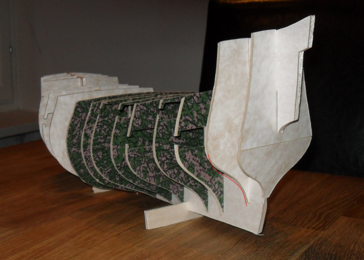
So far I managed to set up all the LEDs in the structure, the main deck, and the underwater hull card-layer. Work is progressing slowly but steady and here are some pictures from the progress so far.
Please let me know if you'd be interested in the story "...anno dei 1669...The shipwright Radék de la Sol de la Santa Cruz de Brazíl" and I can update it here.
If not, I'll just post here my research results and the progress of the build.
So much for now.
Rgds,
Radek