


SawdustDave
-
Posts
1,770 -
Joined
-
Last visited
Content Type
Profiles
Forums
Gallery
Events
Posts posted by SawdustDave
-
-
Beak refinement....
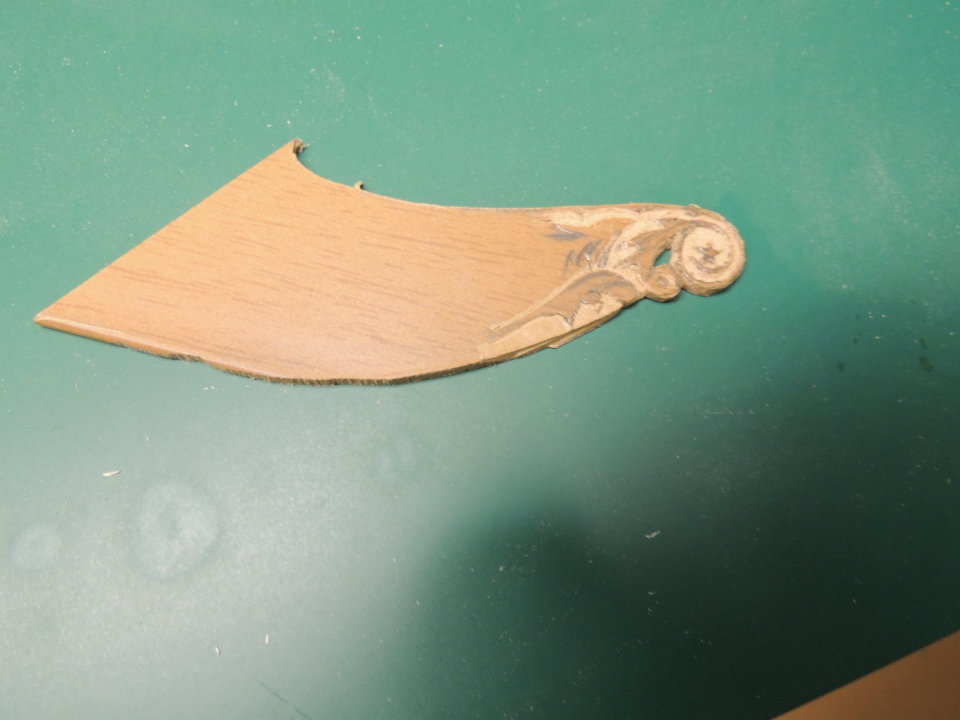
The last posting was an experiment, but needed refinement in order to entirely work. The idea to use a router to create and inlay proved to have issues in terms of allowing me to attach the bow stem to the assembly now, yet allowing me to work on the beak carvings off ship.
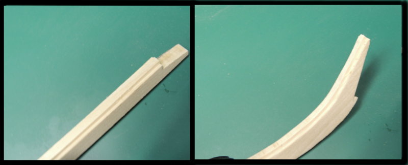
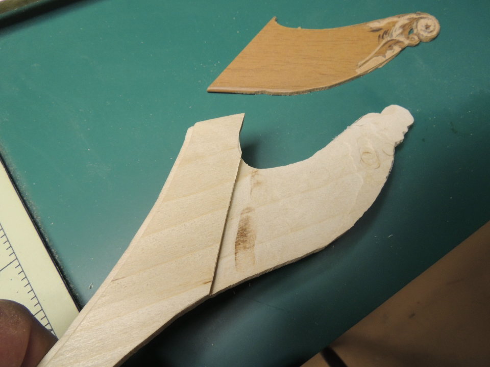
I worked it out by completely whacking off the beak and creating a tongue-and-groove beak that can be added after completing the carvings.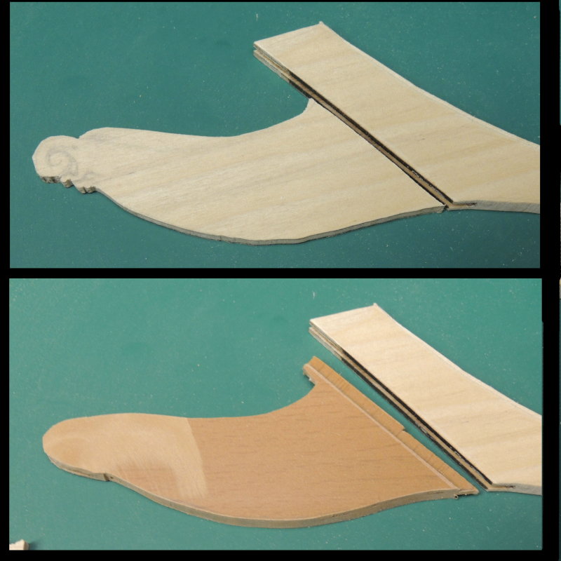
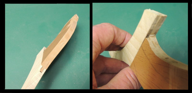
Problem solved!
-
Thanks Pat, CapSteve, and Piet....and for a host of other old MSW friends hooked up on this little project.

Happy New Year all!
- JesseLee, CaptainSteve, Jack12477 and 5 others
-
 8
8
-
-
Thanks Patrick....
I should clear up.....in bed by 10:30-ish..... woke up to pee at 4:30 and couldn't go back to sleep with this problem going round and round in my hard head.
Might as well put a pot of coffee on and go to work.... right?
- mtaylor, CaptainSteve, Piet and 4 others
-
7
-
The Billet Head....
I spent a lot of time finding and studying close up photos of the beak .... particularly the billet head. Most interesting was this old photo I found of the original billet head after being removed for restoration.

Since this is something that must be done off-ship, I decided I will need to do the carving before fitting the beak to the keel former. That represents a big problem with gluing up the entire assembly....right?!
Went to bed last night with this on my mind, realizing I would never be able to come anywhere close to creating that detail with the wood I used to create the bow stem....poplar is not great for carving small details.
The solution popped in me noggin at 4:30 am.... Up and to the ship yard!
Four hours later......
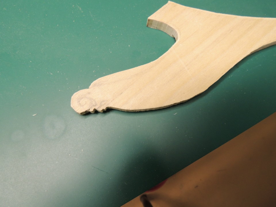
This is the beak as created from the plan pattern....

And here's the beginning of the poly vinyl billet head carving I began working on this morning. Much to go yet, but I'm fairly pleased with the experiment at this stage.

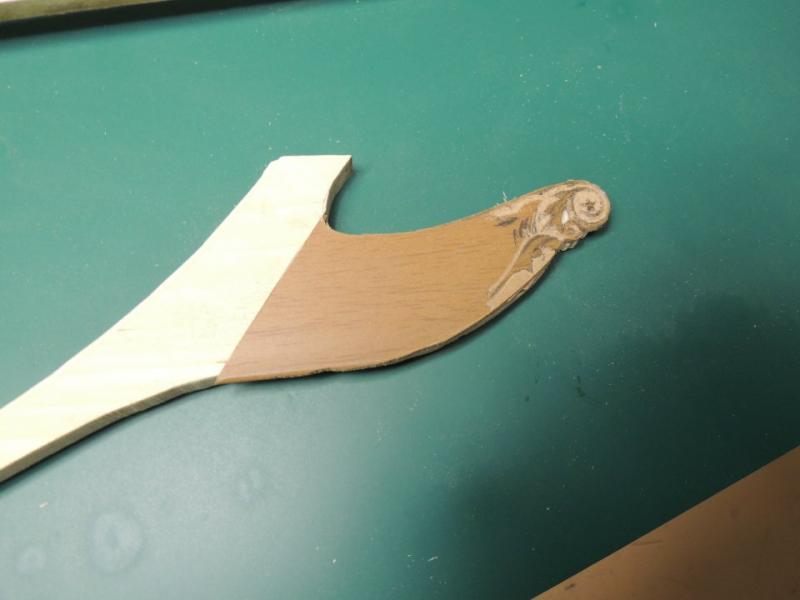
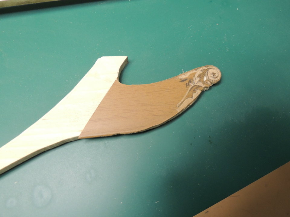
And the simple method that came to me at 4:30 am this morning.... inlay the carving onto the beak!
Used a small router to remove the material from the area where the inlay will be fitted.

Once finished and painted up with black and white details, I'm hoping it will turn out not too bad.
-
I managed to get the rabbits cut last night.
I did take a little different course in the method I chose. Instead of making the rabbit at the bottom of the main keel former assembly, I marked the tips of each bulkhead and re-cut the edge of that entire assembly flush with the marks.Then I simply shaped a slight bevel along the new cut.
Then I re-cut all five pieces of the keel assembly.....which no longer fit the modified shape of the keel former.....
Then I used a small router bit to cut the rabbit along the top edge of the new keel parts, including the stern post and beak.Everything came together real nice in a dry fitting.
- zoly99sask, mtaylor, Canute and 10 others
-
13
-
You're not mucking around with this one are you
 That is significant progress in a very short time.
cheers
Pat
Been told I need to slow down Pat.

- Canute, mtaylor, CaptainSteve and 2 others
-
5
-
Began the morning with my first measurement of the dry fittings of the bulkheads to the center keel.
Great news, and to my complete surprise..... laying a straight edge along the top of the bulkhead beams, every single one of them were perfect.
I fully expected to have some highs and lows that would require some tweaking....right?
This is kinda scary to me mates. I'm accustom to trouble....always prepared for a fight.
I think I can proceed to marking the bearding line and begin cutting the rabbit before attaching the keel and stern post.
- usedtosail, CaptainSteve, Canute and 5 others
-
8
-
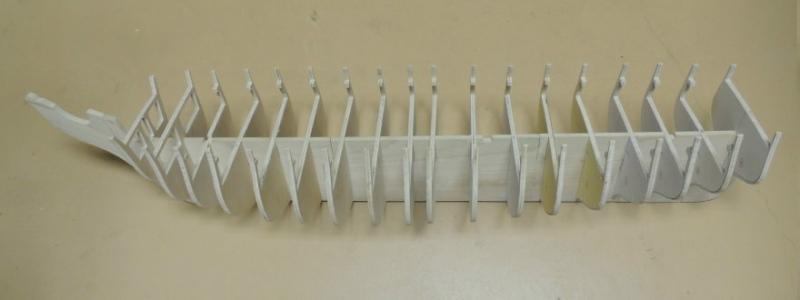
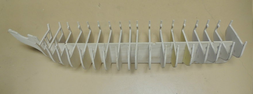
Bulkhead former's all cut out....
Finally finished cutting out all of the bulkhead former's and fit them into their slots on the keel former. Can now begin marking and cutting in the rabbit before adding the keel and stern post.
Then, of course, comes all the squaring, and measuring, and aligning of each bulkhead.
Note, all of the top beams have been removed from fifteen bulkheads, allowing the possibility of installing a full gun deck.
I have not yet decided just how far I will take the gun deck.... still studying photo's.... looks like a lot of exciting possibilities.
-
-
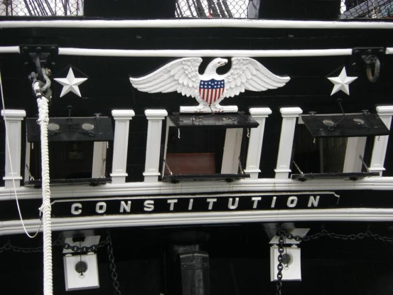
Just now beginning to browse for photo's to draw from. Holy Molly!
I'm beginning to feel like a "pig in a huge mud puddle".
Photo's like this is music to my ears....
But that eagle is a loooooong way off at this point.
- Ryland Craze, Canute, Elijah and 11 others
-
14
-
-
More good news (for me)....
Very pleased to see that all of her artillery is finished in black..... which allows me to create cannons to scale by turning a master, creating all of the cannons from molds. This was one of my big concerns relating to going with 1:60th scale.
-
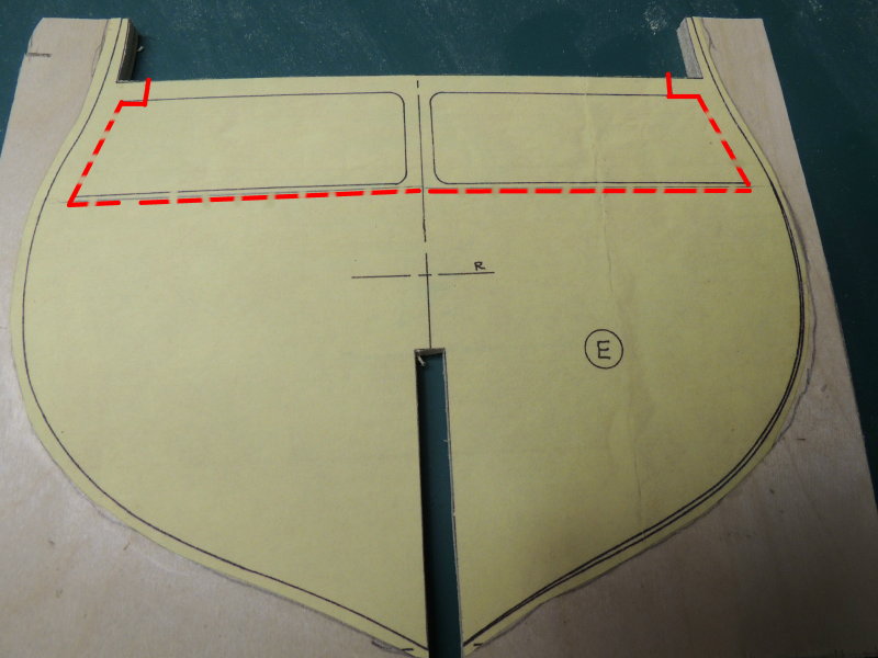
With all my focus up to this point being on just getting plan sheets scaled and printed etc. etc..... completely missed the gun deck option and how you guys have done yours.
Now, after spending more time on your logs, I think I understand what I must do to cut some of the patterns to accommodate the creation of a gun deck between bulkheads "E" through "L".Remarked the eight patterns like the pic below.
Looks like I'm in for a real sawdust day.
- tadheus, CaptainSteve, Canute and 9 others
-
12
-
Thanks for the tip Tom. For sure, now would be the time to do that.
Is adding a gun deck an option to be found within the instructions?
I'm actually beginning to wonder what the useful purpose of those two cut-outs in each bulkhead former. Assumed it was for planking, but after going through the instructions, it appears there is no planking of that deck.
So, the question becomes, If I do not intend to add planking to that gun deck.... Why should I go to the trouble of cutting out those two areas on each bulkhead former?
Anyone?
-
Cutting out bulkheads....
I'm not sure if this posting makes much of a real contribution to my experienced friends, however.... I'm hoping a few modelers taking their first shot at scratch building might find it helpful.
Creating the bulkheads from plan sheet patterns can be a rather lengthy process, requiring several stages of development..... printing the patterns, rough cutting plywood blanks for applying patterns, gluing patterns onto the plywood blanks, then cutting out the patterns, cleaning up the cutout part and fitting to the model.The bulkhead patterns seen here demonstrate an example of an issue faced by the scratch builder.
In order to remove the material from the two spaces within the bulkhead with a band saw, it is necessary to cut through the top of the pattern. After removing the entire area, I have simply inserted a replacement center post and added a space filler where I made the cut.
These three bulkheads are used to show the three stages. The yellow one is a plywood blank with a pattern glued and allowed to cure for at least an hour.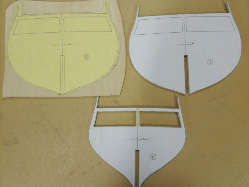
Of course, I should note that using a scroll saw does eliminate the need to cut into the pattern.
-
-
-
-
Hi Greg.... Referring to posting #10 above- that photo shows the clamping of the single 1/2" wide strip I added to the bottom of the assembly which was necessary for me to get the complete width BEFORE adding the false keel pieces.
In other words, the false keel has not yet been added.
But....yes I did use a straight edge AND "C clamps" in that glue-up.
Welcome Al Jesse and Mark.
-
Darrell.... All I can say is that I have many friends who have given me sets of plans after they have finished their build and no longer need them.
I did find a site with plan sheets for the Connie, but found them to be considerably inferior for my taste.
Just do a GOOGLE search on "free plans for USS Constitution"..... actually costs $2.
-
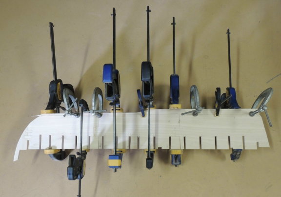
Clamps of every size and shape is the bread and butter of every woodworker....right?
The width of the lumber used to create the three main keel parts was about 1/4" too narrow for the pattern. So it is necessary to add a strip to the bottom edge of the assembly.
Not bad actually, as the solid continuous strip strengthens the joint between the three large parts.
Once cured, I will be able to trace out the bottom line and cut the full assembly to it's final shape.
- Geoff Matson, Jack12477, mmdd and 10 others
-
13
-
One more quick tip....
Just for those friends just getting in to the hobby.I find it really helpful to use this little digital timer to make sure I allow my glue-up's to dry properly before handling them.
It's so easy to lose track of time, or become impatient and grab an assembly before the glue is fully cured.
Seen here, the three main keel parts have been placed on my table saw top with two heavy tool boxes securing the joints while the joints are curing for an hour.
The timer will alarm after the set time, as a reminder that I can begin handling the assembly.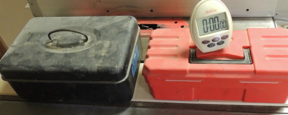
-
OK gang....... just created new topic under Scratch Builds Forum.
See ya there!
- CaptainSteve, JesseLee, Omega1234 and 3 others
-
6


USS Constitution by SawdustDave - FINISHED - 1:60th Scale
in - Build logs for subjects built 1751 - 1800
Posted
Hi John....Man, would I love it to be so close to any ship I'm trying to build.
Great offer, but with all the great photo's out there already, I wouldn't begin to know what to ask for at this stage.
I do know I am planning a spring trip....after I get a little further along.
Maybe we can hook up somehow when I go up.
Dave