


SawdustDave
-
Posts
1,770 -
Joined
-
Last visited
Content Type
Profiles
Forums
Gallery
Events
Posts posted by SawdustDave
-
-
-
As a favor to my very good friend Dr. Andrew Hendricks (my dermatologist), I have interrupted my scratch build of the USS Constitution for several days in order to repair this very old model of the Half Moon which was gifted to him by a friend in Italy.
The model is well over fifty years old, and the original builder is unknown. In shipping from Italy to America, the poor job of packing and securing it in the crate resulted in considerable damage to the fragile rigging and a couple of masts. Also, it appears the model had been stored is a very dusty place over the years. It may have been the dirtiest model I have ever seen.Dr. Hendricks is a major partner in a group of investors who, several years ago, raised over a million dollars for the building of a full size replica of this historic ship (Dr. Hendricks is seen in the middle of this photo).
Another model of the ship is seen behind the three investors.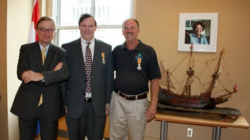
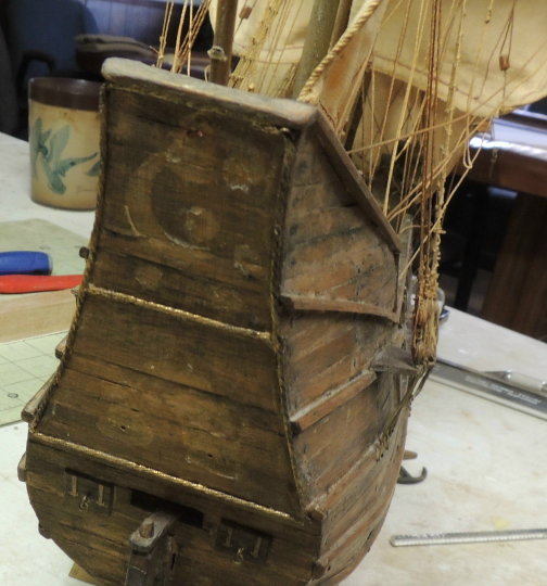
He gave me a call immediately after opening up the shipping container and discovering the condition of the model he was so looking forward to receiving.
Here's what he saw....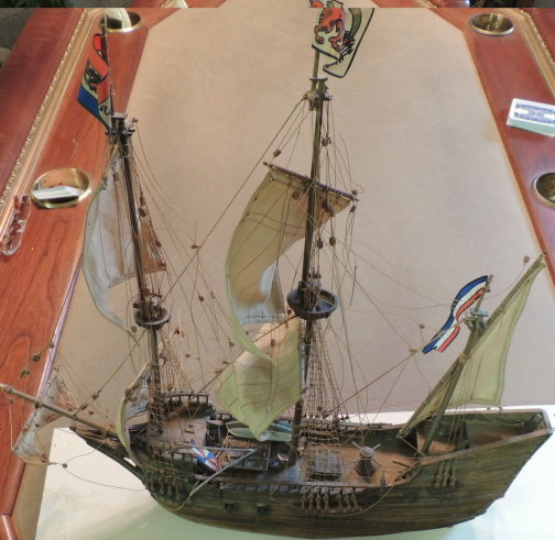
While the damage to the rigging was considerable, I found the the heavy line used managed to remain in tact without breaking, in spite of the age.
Much of the breaking occurred at belaying points along the spars where small thread was used to attach rigging blocks.
After reattaching all of the rigging, I had to spend several hours on re-tensioning quite a few drooping lines.Then there was the cleaning.....
Boy! Was she incredibly filthy!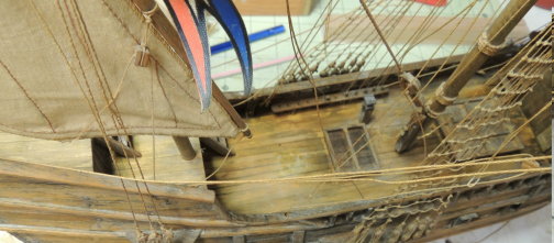
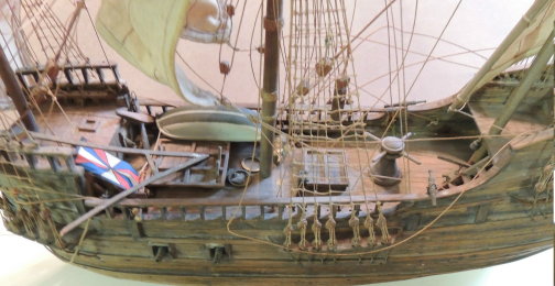
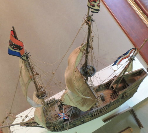
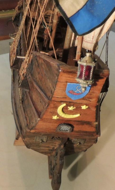
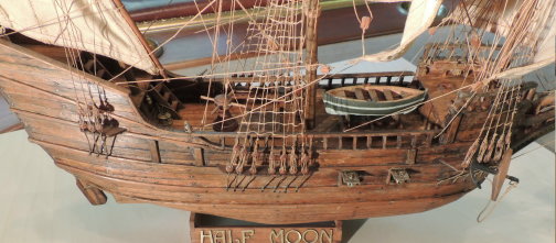
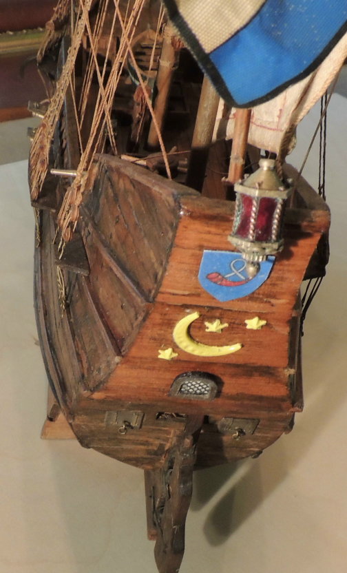
Here's a few shots of the finished restoration.
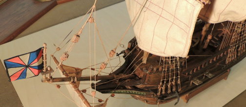
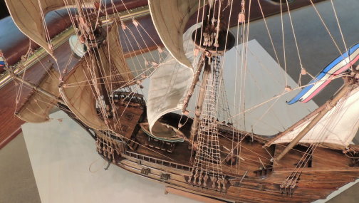
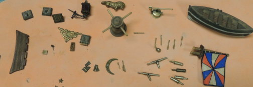
I did create the coat of arms shield for the city of Horne and also the single arched window to the transom.
- mtaylor, Piet, GrandpaPhil and 1 other
-
 4
4
-
-
Hi Jon.... Thanks for the visit.
Routers..... Being a long time old wood worker, I have a number of routers of different sizes. The DeWalt I have mounted underneath a table is the one I use most because I can set up fence guides for best control. I occasionally use the Dremal router attachment as well.
Other tools.... table saws, band saws, and drill press.... vertical and belt sander, vibrating sander, plus a few different Dremal Tools.
In other words, if makes noise and creates sawdust, I will find a use for it..... yahaha
Dave
-
I don't expect this posting to be of much value to many experienced modelers, but for the few who might be faced with creating scratch planks, here's how I approach it.
In other words, turning a choice piece of 3-1/2" X 1/4" poplar into a pile of deck planks....
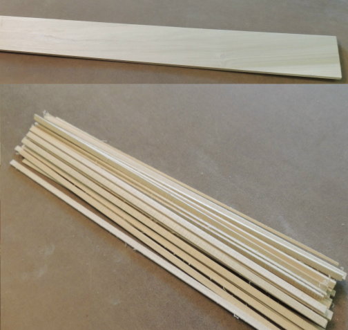
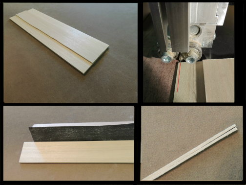
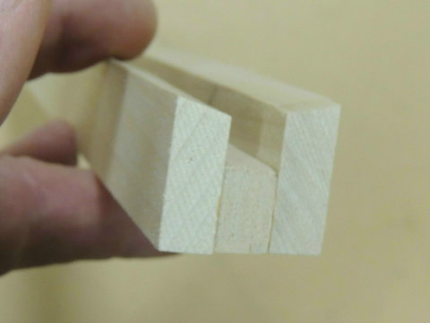
Before ripping the thickness of each plank on my band saw, I had to remove some width of the planks by passing the board through the table table saw. Standing on edge, the height of the blade is set to remove only about 3/4".... safely.
One pass on opposite edges gives me 1-1/2" of perfect plank width to take to the band saw.
Note that the edge of the board represents the width of each plank.
The plank thickness will be determined by the band saw cuts.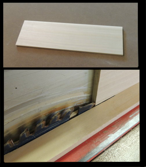
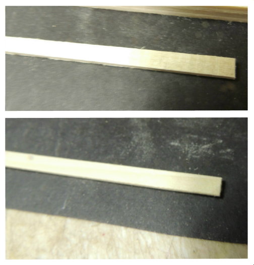
After each pass on the band saw, creating the thickness of the plank, I use a long sanding block to re-dress the edge, removing the rough surface caused by saw blade.
Done properly, the last cut will be something like the lower right pic.
Finally, each plank must be completely dressed with a long sanding block to remove the roughness caused by the band saw blade.
Quick note about the sanding block I use for dressing planks....
Years ago, I purchased a roll of this 100 grit paper used for safety "non-slip" concrete floors and stair treads. Can't tell you how many sanding blocks I've made with this roll.
The important point being.... compared to the typical sanding board we have all used (top right), this stuff will seriously remove material like no other sandpaper I've ever used.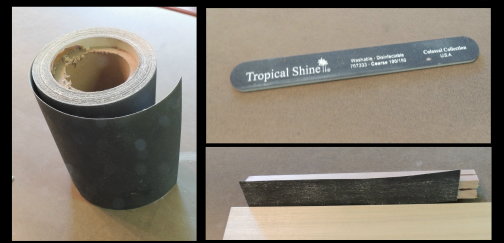
- Canute, zoly99sask, tadheus and 11 others
-
14
-
-
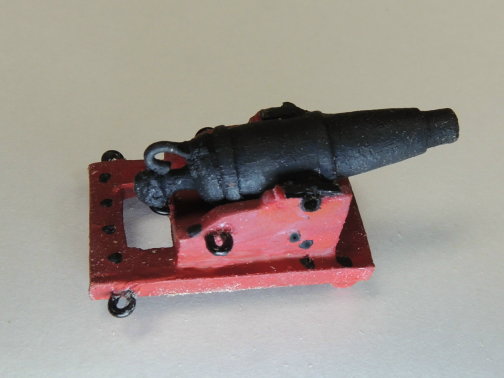
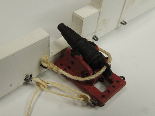
After several days of working on prototypes for cannons and carronades.... including their carriages, and rigging.... I guess I'm about ready to move back to the ship for a while.
With so many of these guns to create, I'm hoping to get the technique for creating and installing them down to within reason. The mock up of a gun port has been invaluable in that respect. I came to the conclusion that a few trade-offs was necessary in terms of being able to install each gun.The hooks that attach the block to the bulwark has to be much longer in order to get them to anchor into the eye rings.
I also learned that all rigging must be attached to the carriage and cannon before attempting to install.
Also.... the cannon restraining rope must be hooked in place before attempting to hook the block and tackle hooks.
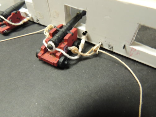
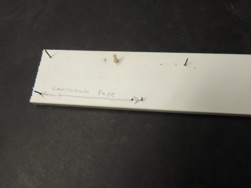
Finally, I was able to develop this little jig which will be used to make all of the rigging the exact same length.... very critical.
With 30 long guns and 24 carronades needed, my plan, for now, is to build three long gun and two carronade modules per week as I continue with progress on the ship..... in 10 weeks I should have all the guns completed.This is, by far, more fully rigged guns than I have ever installed on a ship.
-
Scaling the cannon prototypes....
I'm glad I paused to do this, as it turned out to be a little more involved than I anticipated.As we all know, while there are a good number of other things to work on, the gun deck of this ship is mostly about the guns.... lots of guns! Same goes for the spar deck. Also....Guns also mean gun carriages and rigging.
Having said all that, my primary concern being scale, and having a reasonable method of creating all the parts.
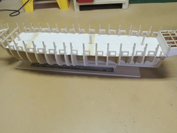
First, a quick shot of the framing of the gun ports for the gun deck..... note that I have created a cardboard deck which can be marked up for all of the fixtures that will be added, in addition to the guns. I located the masts on the deck in order to index the entire layout.
The next pics show the development of the carronades and carriages and rigging.
Created molds for the carriage parts....
24 carronade carriages and 30 long gun carriages will be needed.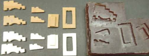
Each of the carronade barrels will be turned from hard rock maple.
I also developed a mock up of the bulwarks in order to work out the exact size of the rigging blocks, hooks, and rope. This is the part that was little more difficult than I expected.... mostly block and rope sizes.
I'm working on the same mock up for a long gun prototype.
- zoly99sask, CaptainSteve, Elijah and 10 others
-
13
-
Thanks to the many PM's here and on FB ON MY 74th birthday.
Great news from my dear son and daughter who called this morning to wish Dad a happy BD, and inform me that they were treating the old man to a trip to Boston and three days to take in all of the details of the Constitution first hand. Not only that, but my son is going to join me there in Boston. That will be a DOUBLE treat!
Meantime, back in the ship yard.....
Reason for the lul in progress is due to a ton of off-ship work.... mostly related to the realization that I will eventually run into a s....t-pot load of cannons and carronades including carriages and rigging material for each. All being a scale I had no idea what I will need.... etc.
I hate the thought of completing her gun deck and then beginning the arduous task of building and installing all those cannons. I would much rather, and hope to build and install her cannons as the gun deck bulwarks and deck planks are developed.
So, the entire last several days has been focused on building prototypes for her long guns and carronades.
Hopefully, I will be able to post a few progress shots tomorrow.
- UpstateNY, CaptainSteve, Canute and 9 others
-
12
-
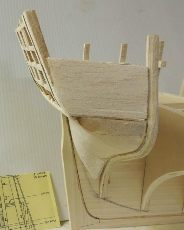
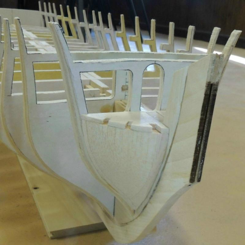
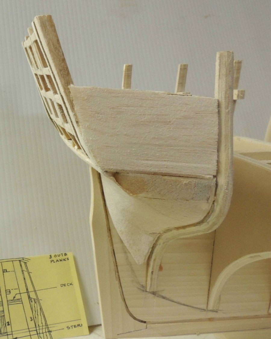
Transom re-framed....
Three days later.... a little over twenty hours of ripping out and fixing this very important part of the model.
Here we are back to the same point.....
First, the transom frames are now well aligned with the widened filler block.
Also, the frame-to-frame alignment has been fared left to right and top to bottom.
Finally, the six window openings measure precisely to the plan sheets.
-
Glad I brought this issue up, as it did cause me major heartburn. That profile diagram of the stern assembly caused me to make the counter block too narrow, as noted by Tom in his analysis of my problem.
Thankfully, I will be able to fix the problem with considerable woodworking techniques, requiring complete rip out of all the framing I had finished over the last three days.
I'm sure this will not be the last, nor the worst mistake I will make with this project..... life of the scratch builder.
Thanks Tom.
-
Tom' response further confuses my old brain..... easy to do.
I created the posting above by taking the frame pattern directly from the plan sheet and transposing it directly over the profile of the assembled stern taken from the plans.
Note that my stern filler block is a perfect match to the plans.....AND..... by taking off the 1/4" the transom frames I get a flush fit with the back edge of the filler block just as you stated.
It's not nice to mess with old people's minds. Hehehehe
BTW....for all you snowbirds who play golf..... we have mid 70's and sunny here in NC today. January golf! YES!
- CaptainSteve, Piet, Landlocked123 and 2 others
-
5
-
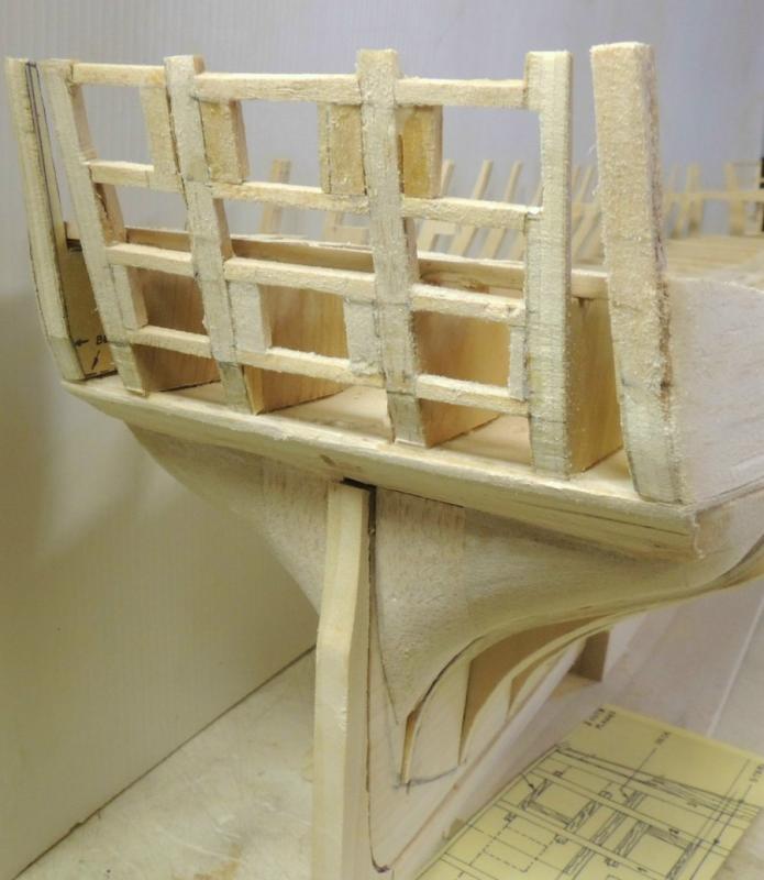
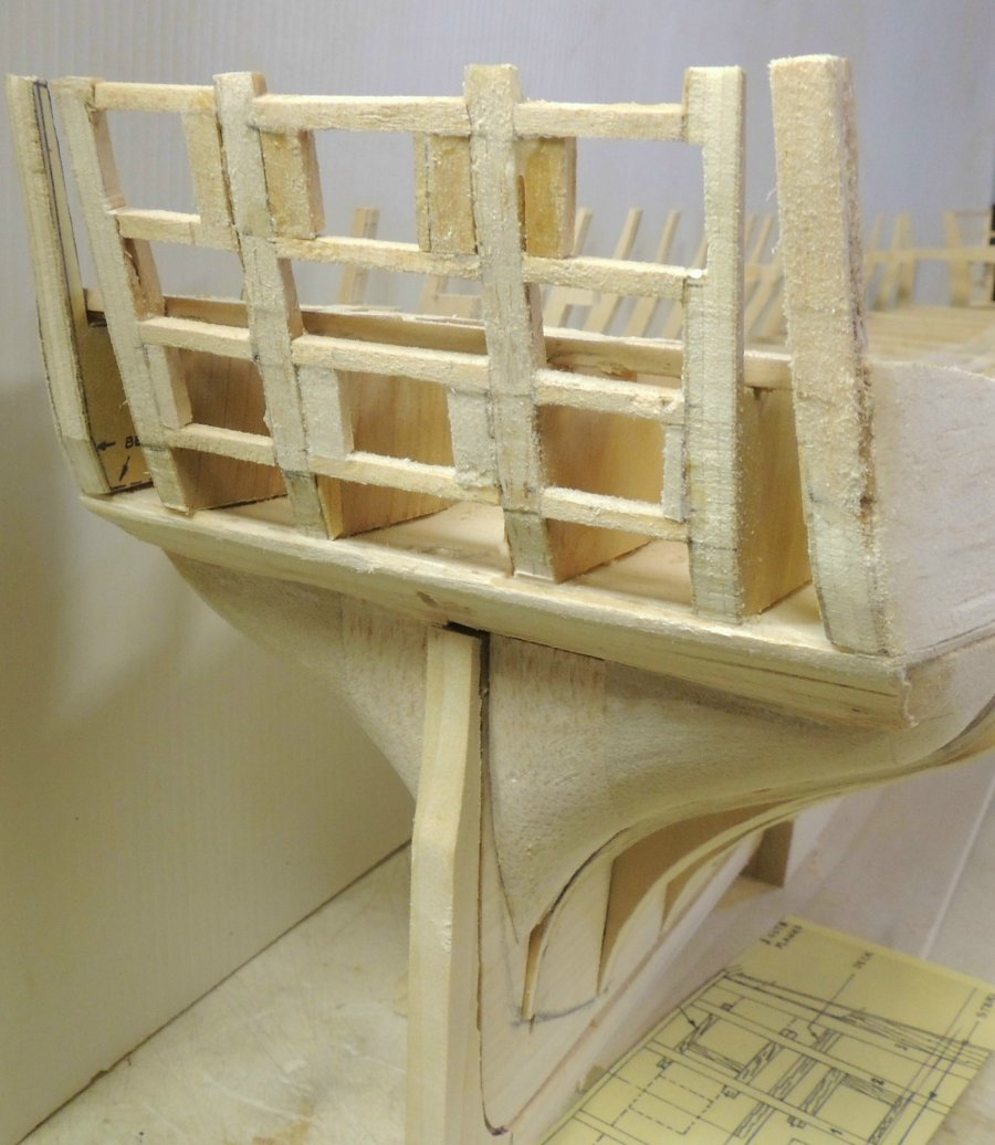
Working on the stern framing.... I ran into this little surprise regarding the plan patterns. I'm curious to know if it's just me, or did any of you Connie builders run into the same issue.
When you lay one of the frame patterns over the profile of the assembled frames (as seen below), you find that a full 1/4" has to be removed from the length of the frame in order to align the aft edges flush with the stern filler edge.
This caused me considerable heartburn yesterday as I went into a scramble of checking and re-checking the width of my stern filler against the plans, then checking my frame parts against the plans, and checking Tom's build log to assure me I was interpreting the plan sheets properly.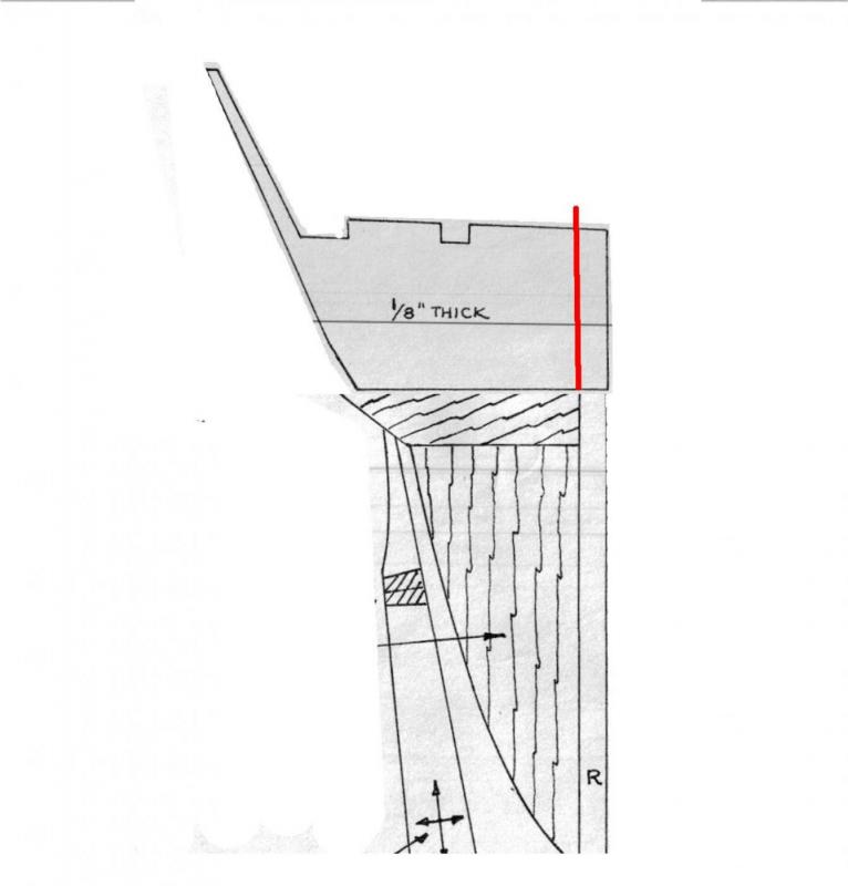
.
- Canute, zoly99sask, Piet and 4 others
-
7
-
Hi Pat!
What CapSteve said....
Thanks Cap
- Piet, Omega1234, CaptainSteve and 3 others
-
6
-
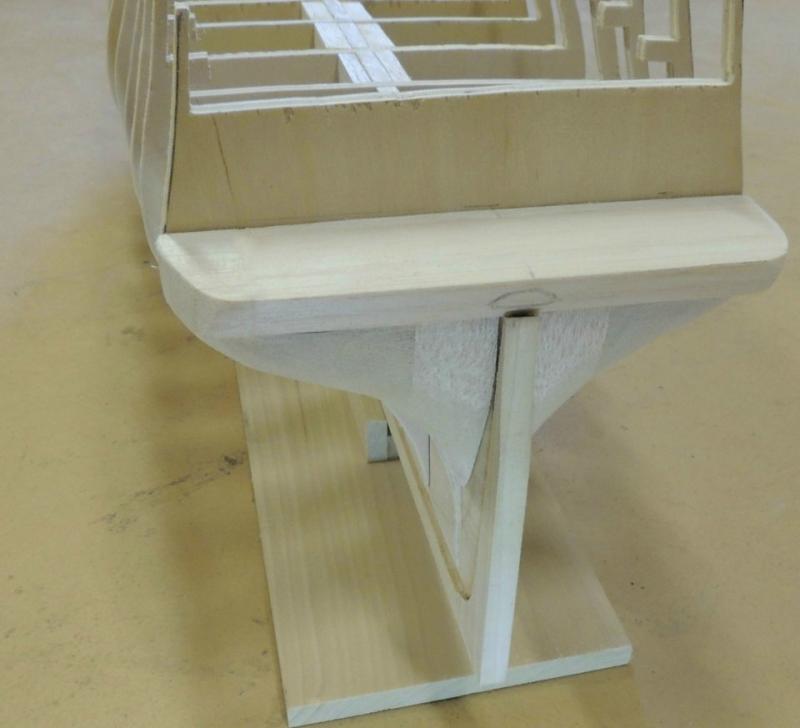
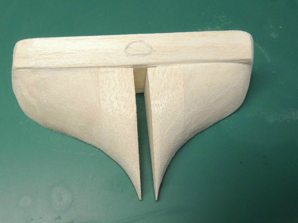
Filler blocks - bow and stern....
No attempt to show any step-by-step log regarding the creation of these filler blocks. For that, I refer all builders to visit Tom's (usedtosail) impeccable documentation of the process (never mess with perfection).Three quick shots taken this morning after finishing up the fairing of all the bulkheads and shaping the fore and aft filler blocks.
Note, I did choose to glue up the three stern filler blocks so I could work on them off ship.... dry fitting and marking them several times as I slowly achieved acceptable shape and fit.

Loved Tom's woodworker approach to notching the bow filler blocks..... sure did make a clean job of that task.
- usedtosail, Omega1234, Jack12477 and 12 others
-
15
-
Hi Nigel - I am also happy to see you back to your Confederacy (my favorite build of all time). Personally, I think this is Chuck's finest work ever.
Treenails.... I find pulling bamboo through a draw plate produces the best treenails of anything I've tried.
Beautiful job on a beautiful subject mate.Cheers
-
I should explain the tooth pick Greg.... sorry to mislead.....
I do have a very fine brush, which was used for the first two coats of white acrylic. Then after allowing the paint on my pallet to set up and become somewhat thicker, I used a sharpened tooth pick to apply a raised layer in those fat areas of the scroll work where I wanted more relief detail.
In other words, the thick paint was "piled up" and then pressed into subtle shapes with the tooth pick.
Kind of tedious, but the result was not bad in that it did add a subtle dimension to those flat spots.
- mtaylor, CaptainSteve, Piet and 6 others
-
9
-
Thanks for the nice words Jesse, but I'm afraid watching the process would be about as entertaining as watching grass grow. Very slow process indeed for sure.
Here's another tip for wood carvers.....
After doing the rough carving, and then "refining" the detail to the point that it is beginning to appear fairly acceptable.... take two or three close-up photos of the piece using different angles and light reflections.
Then use the photos to mark areas of the carving you want to re-visit and work on, either to clean up or change the shape.
Then take some more photos, and go through the same process again.
Point is, the human eye simply will not pick up on the type of imperfections nearly as well as the camera.
I must have taken a thousand pics of the carvings I created for the SOS project.
Cheers. -
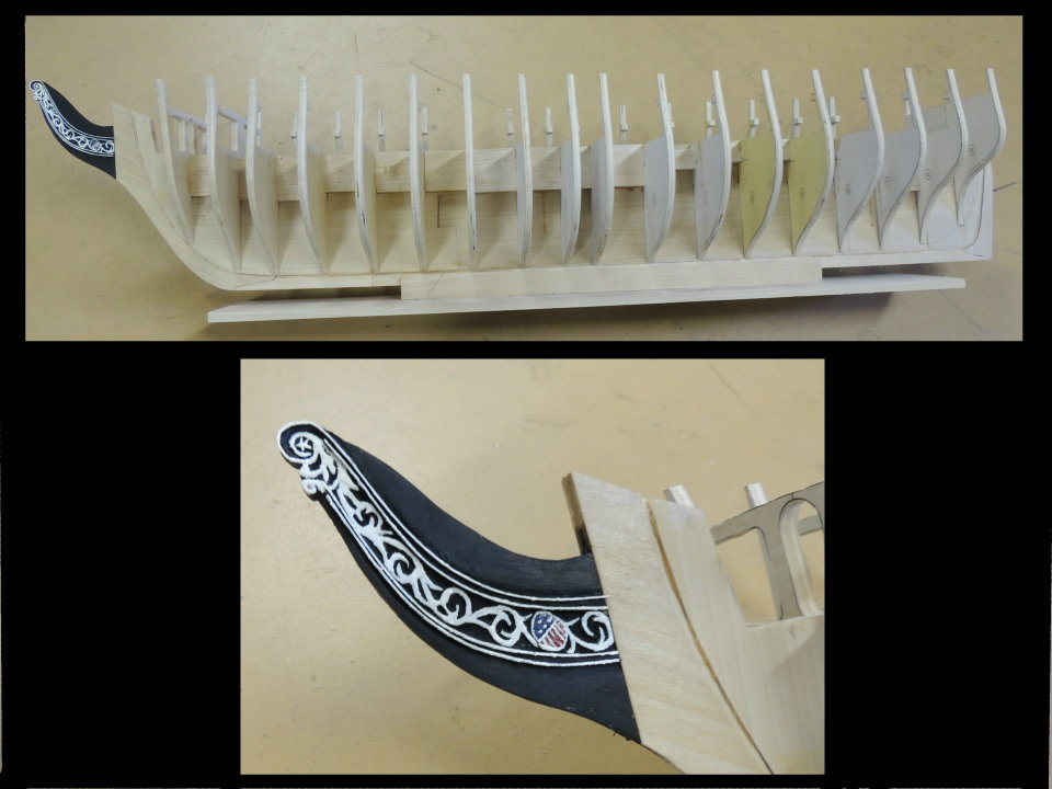
Beak painted ....
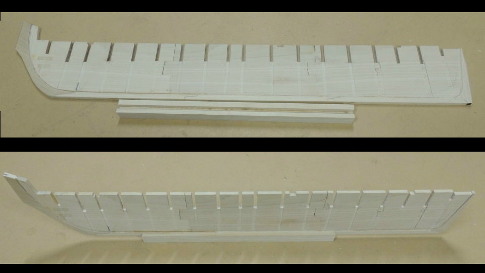
All bulkheads fitted to the former with careful measurements taken to insure precise spacing at the outer edges and top surface alignment from bow to stern.
Next task of fairing the edges and creating bow and stern filler blocks.Also, I finished the starboard side carvings and painted the whole beak flat black. Then used a straight razor blade to scrape the top surface of the carvings clean, leaving the black background.
Then added the delicate double trim rails above and below the carvings and painted them flat black.
After three coats of acrylic white, mostly applied with a tooth pic, completed the beak by painting out the red/white/blue shield....again, acrylic paint applied with very sharp tooth pic.

- UpstateNY, CaptainSteve, BANYAN and 19 others
-
22
-
Did anybody else notice the gallery windows behind the billet head in Dave's picture? Looks like the are painted on.
That's such an old photo Kirby.... taken by Leslie Jones in 1927....I kinda doubt it's been doctored over the years.
- CaptainSteve, Piet, Omega1234 and 3 others
-
6
-
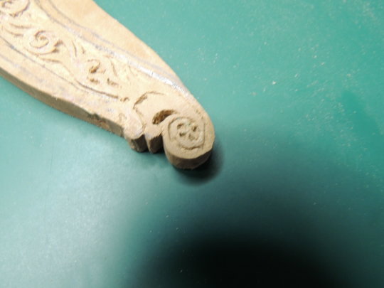
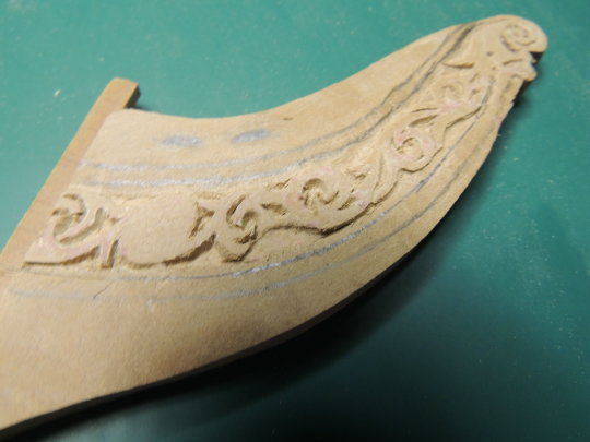
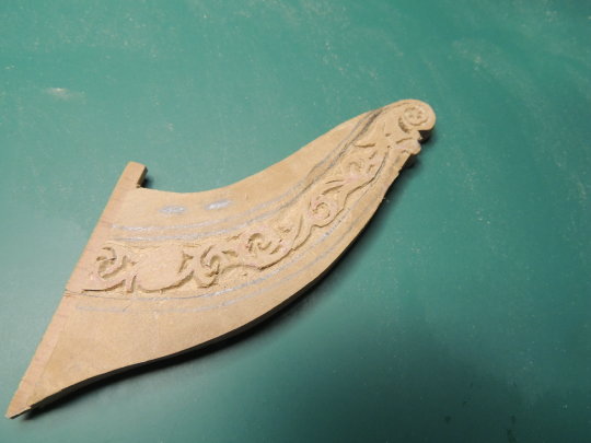
Billet head carving....
Giving each bulkhead an hour under the clamps gives me time for some carving on the billet head.
Using one of the photos taken from the net, I have managed to rough out this relief carving for the starboard side.
Looks pretty rough for now. I'll have to leave everything as a flat surface for now until after I eventually paint the entire piece black.
Note - I haven't worked on the oval area of the flag yet.The pencil marks indicate the upper and lower rails which I will begin playing around with after carving the port side of the beak.
Eventually the knee with the howse holes will be created to blend into the beak and I will have to continue the carvings into that knee.My plan is to paint the whole thing flat black, then carefully remove the black from the top surface of the relief with a scraper and try to paint the white scroll work. At that point, I can work on getting some of the subtle detail to the scroll "leaves".
- zoly99sask, Canute, BANYAN and 12 others
-
15
-
Was wondering what the heck was going on with you mate.
"Burn-out" happens to all of us....this is a very intense hobby, and after a while we just need to step away rather than allow the quality of our work to suffer. Am I right?
In my case, I took almost two years break.
Missed you and, as with everyone else, excited to see you back.
Dave
- Piet, Ryland Craze, mtaylor and 1 other
-
4
-
-
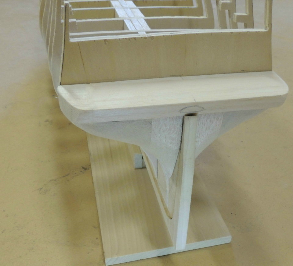
Keel former assemble done.....
Removed the assembled keel former from all the clamps first thing this morning. Note the missing beak.Looking closely, you can see that each of the bulkhead slots have a perfectly square track created with a 1/4" router bit.
The shallow track is routed to both sides of the former.... creating a very snug fit for each bulkhead and perfectly square to the former.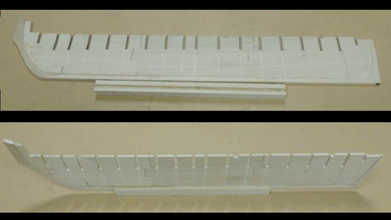
Also removed the holding base from clamps I glued up yesterday.
I will probably add a two inch wide board to the bottom of the holder base in order to have a really stable holder as this model will eventually become quite large and heavy.She's ready for some bulkheads.
- Omega1234, Piet, Erebus and Terror and 8 others
-
11


Half Moon by SawdustDave - Restoration
in - Kit build logs for subjects built from 1501 - 1750
Posted
This restoration is completed to the extent that the model has been restored to it's original state.
Obviously, it could be taken to a much greater level of appearing closer to the replica which was built by the investors. I offered to add the paint scheme seen on that replica, but Dr. Hendricks chose to leave it largely the same as was created by the original builder since he was told by the curator that it probably was much closer to the way the actual ship appeared when Henry Hudson sailed her.
He explained that the paint scheme on the replica was done primarily for the public, and that he was personally opposed to such "Disney World" promotion of the ship he is so proud of.