HOLIDAY DONATION DRIVE - SUPPORT MSW - DO YOUR PART TO KEEP THIS GREAT FORUM GOING! (Only 72 donations so far out of 49,000 members - Can we at least get 100? C'mon guys!)
×


Louie da fly
-
Posts
7,989 -
Joined
-
Last visited
Content Type
Profiles
Forums
Gallery
Events
Everything posted by Louie da fly
-
 A magnificent job, Michael. I just went back and looked at the first page of the build log. What a transformation! You have good reason to be proud of your achievement. I take my hat off to you, sir. Steven
- 749 replies
-
- 5
-

-
- albertic
- ocean liner
- (and 2 more)
-
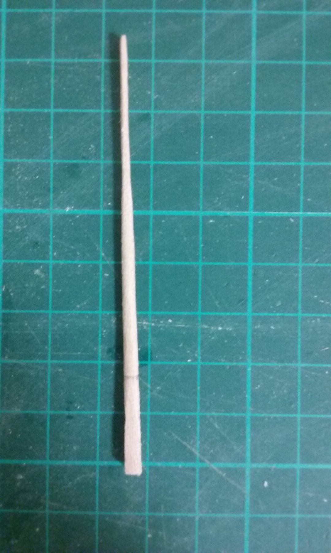
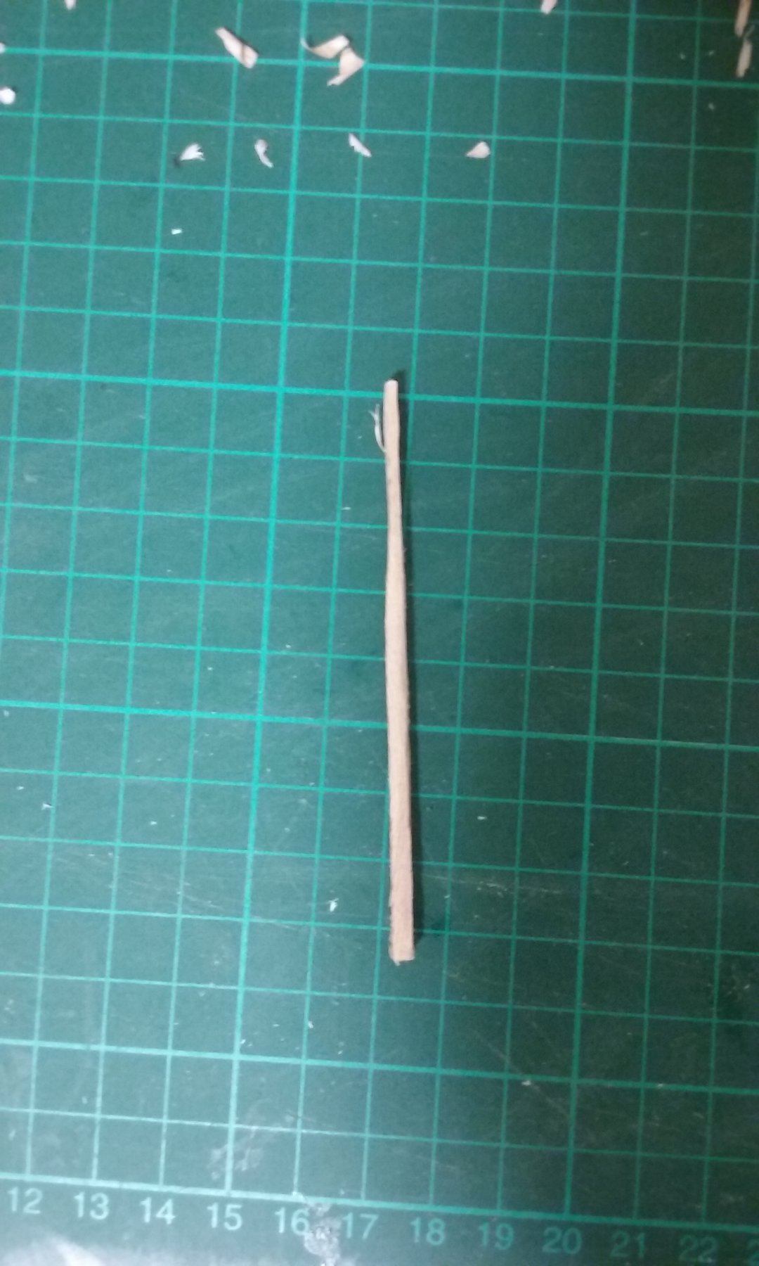
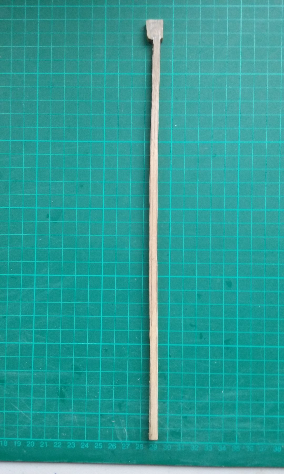
Trimming down with the scalpel to get closer to the standard oar. And further still Side view Shaped the blade - using the file now, as I did on the mast, rotating the oar in my fingers to check for roundness and filing down any lumps and bumps. Cleaned-up with the file and then sanded to finish. Note the pencil line near the base - this is to mark where the oar goes through the oarport. The finished oar side-on. Steven


-
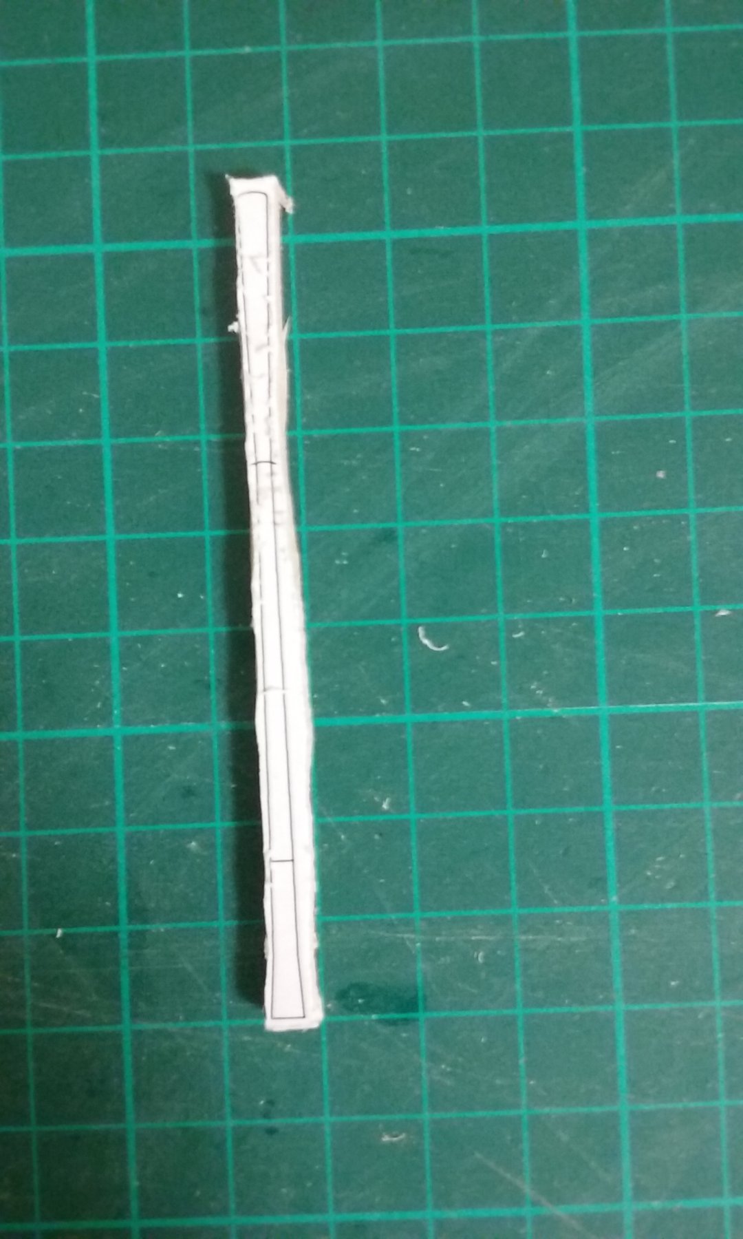
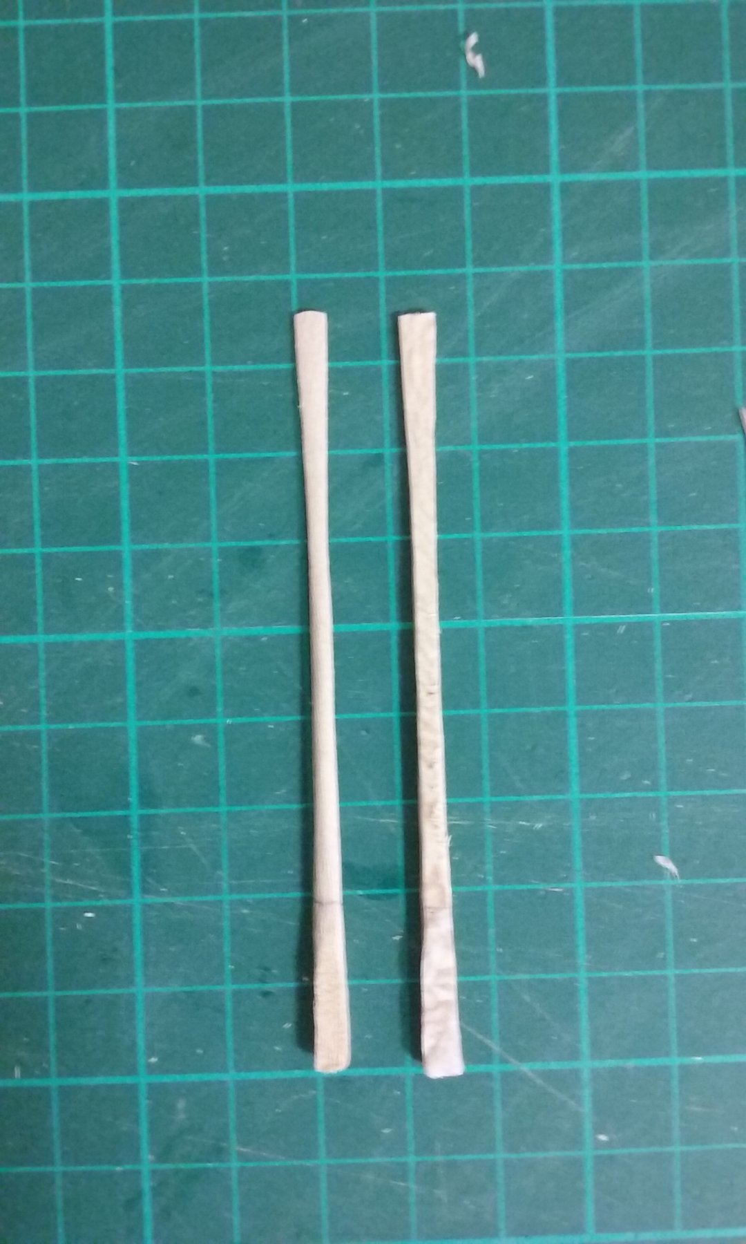
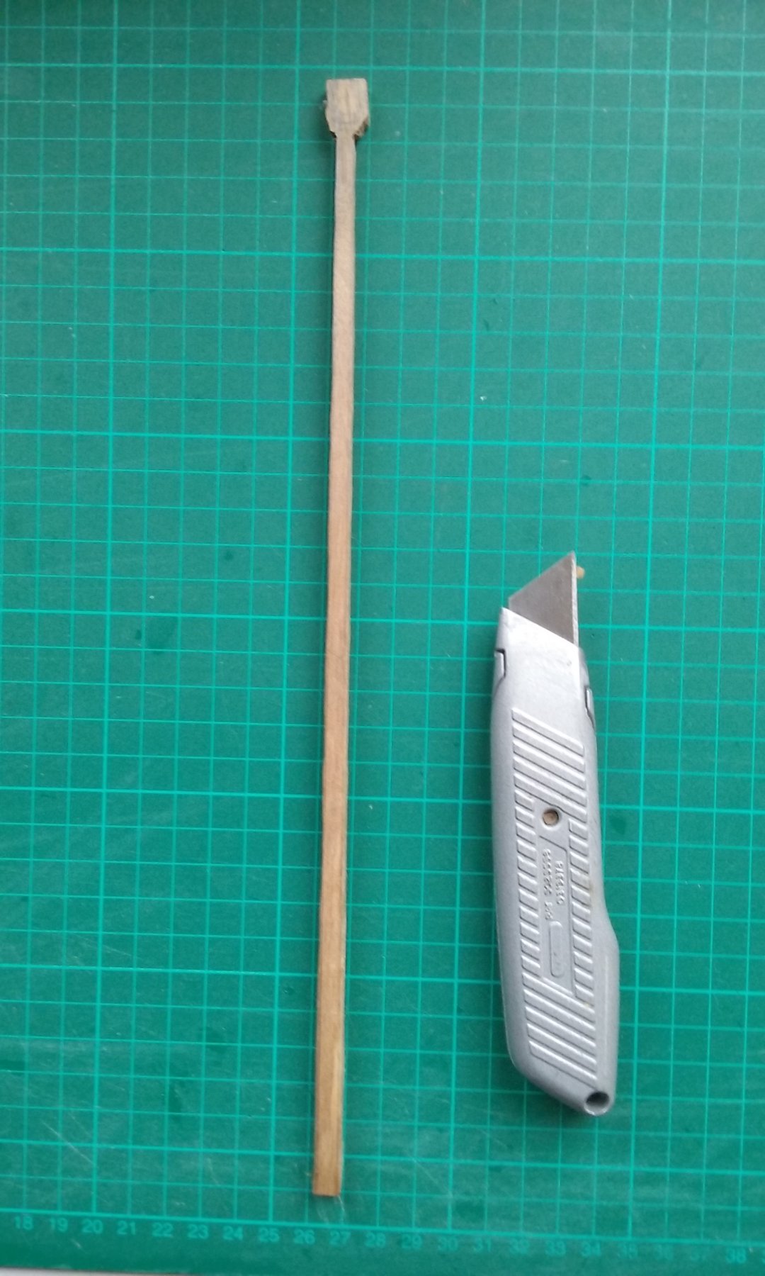
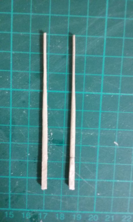
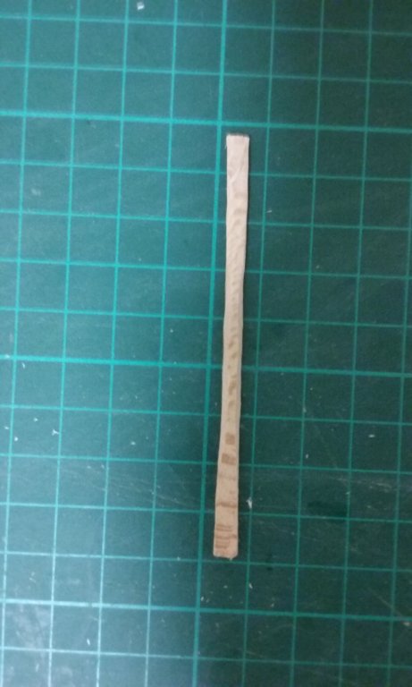
I promised a step by step outline of making a lower bench oar, so here it is. Two of the oars had turned out to be unsatisfactory - one was bowed and the other had a dark blemish in just the wrong place - so I had to replace them. Here's the first oar blank with the outline on paper glued onto a piece of 2mm thick planetree wood. I trimmed it with a No. 11 scalpel till the wood was almost cut back to the outline - leaving a little overlap in case of Murphy. Then I cut faces at 45 degrees to give it an octagonal section and started trimming the thickness to make the oarblade. Comparing it with a "standard" oar - it's quite a bit too thick. Trimmed down further to get the shape closer to the desired one. (Sorry, the new one's on the right this time). More to follow. Steven


-
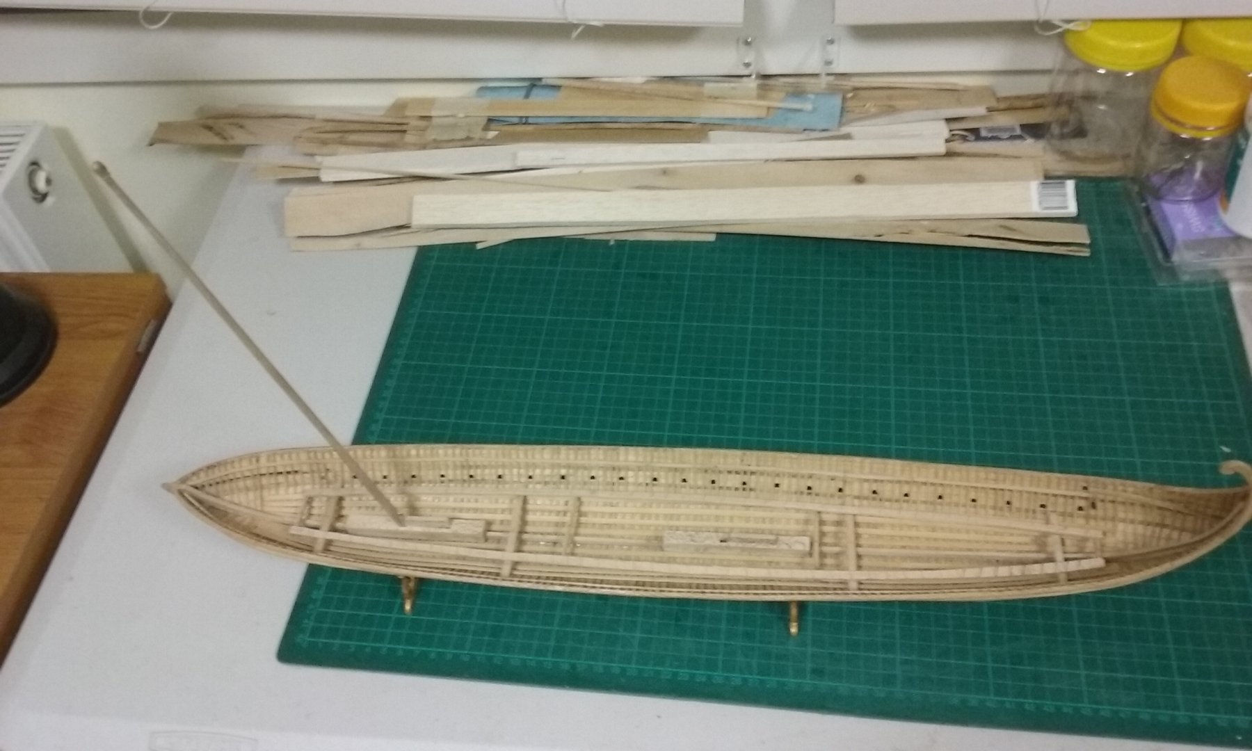
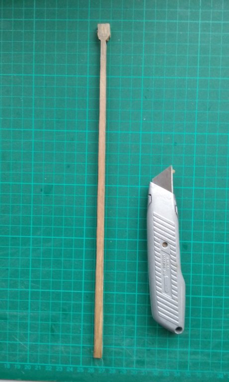
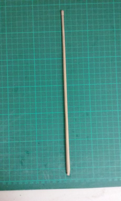
I've made the foremast. I'd cut a piece of walnut with a tapered thickness with my drop saw, and I marked out the two masts and cut them roughly to shape with a coping saw. I trimmed the foremast with a Stanley knife (see picture) as close as I could to the lines I'd marked, and made the faces flat and straight with a file. I left the top rough to start with, because it was going to hold the "blob" containing the sheaves. Unfortunately I got it wrong with the after-mast. Somehow I'd missed the lines and the thing ended up with a bow in it. Fortunately I'd left myself enough wriggle room to straighten it out - barely enough. After it was straight I put it to one side and went on with the foremast. I marked the correct taper for the other two faces of the foremast, and trimmed them so I had a square-section mast tapering from the base to the top, then filed it flat and straight. I cut faces at 45 degrees, to create an octagonal section. Then with the file I turned that into a round section, rotating the mast in my fingers to get the "feel" (which I've found gives a pretty reliable circular section when you don't have a lathe). Cut the "blob" to shape and cut the tenon at the lower end of the mast and dry fitted it into the mast step, adding a wedge to hold it tight against the blocking piece. More to follow. Steven


-
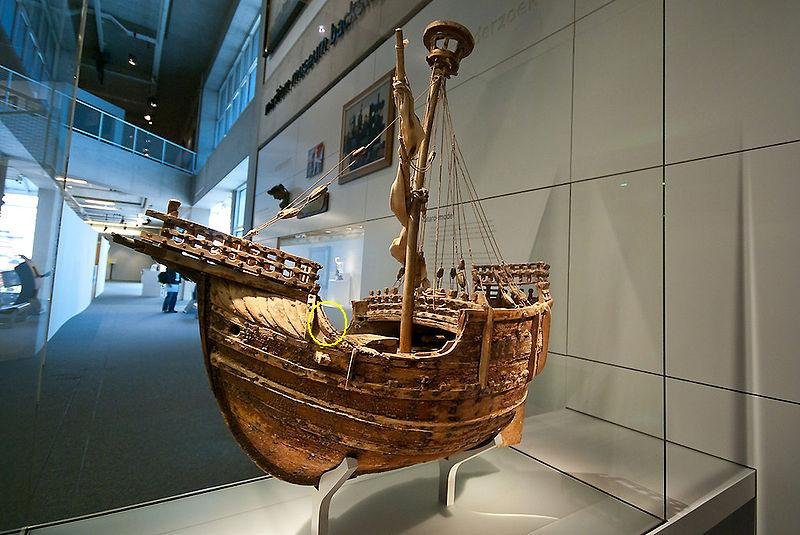
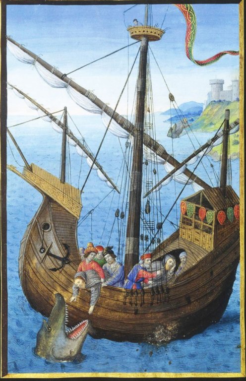
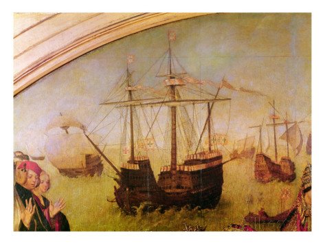
This is a little hard to answer. A lot of contemporary pictures of round ships of this period are shown from the stern so they don't show this detail. Of the ones that are seen from the bow, many pictures (and the Mataro model) just show this area open, presumably for easy access. Others (not very many) show an arch similar to the one at the forecastle. By 1520 this area seems to have been closed in with what might be an arched door leading within - but the carracks of this time were considerably larger. I haven't seen the picture of the Spanish carrack you refer to, so I can't comment. Is it possible to post it?
-
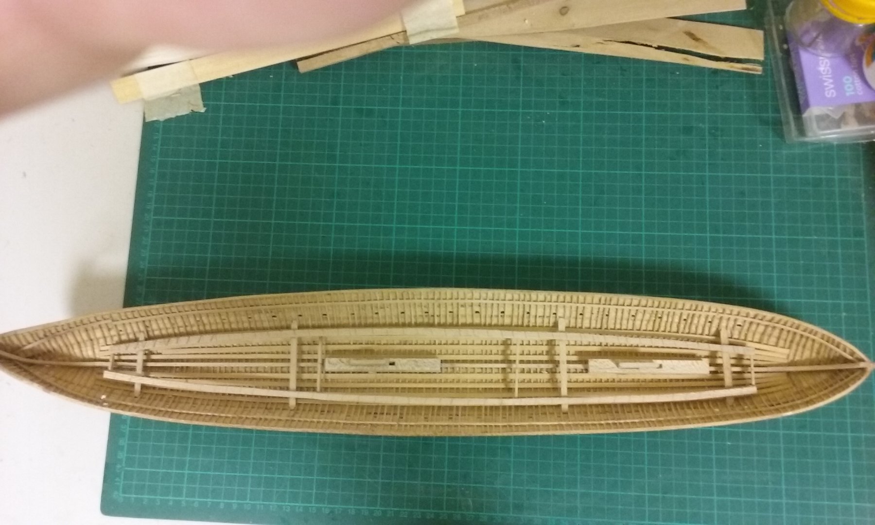
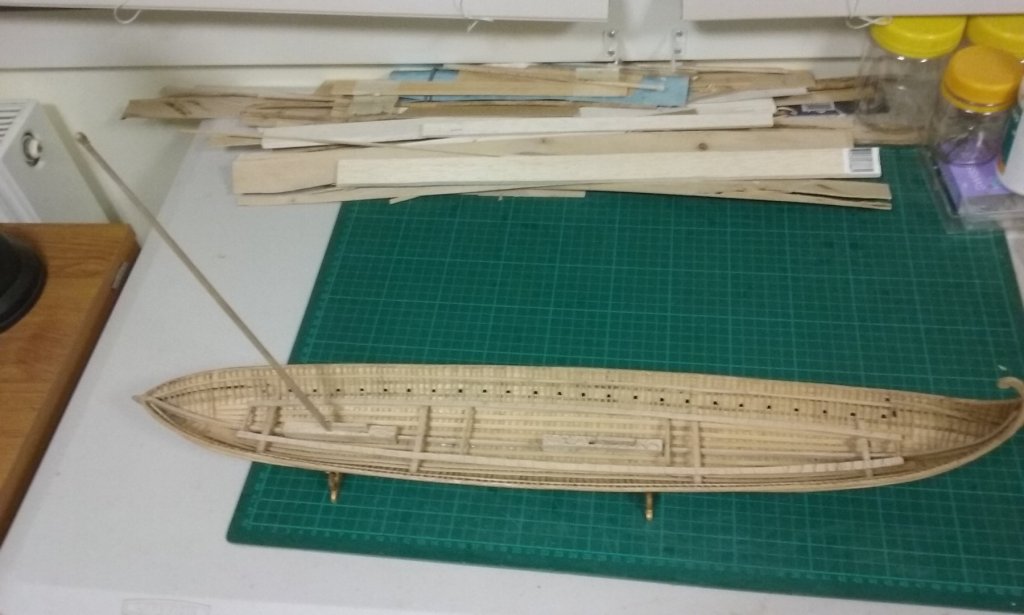
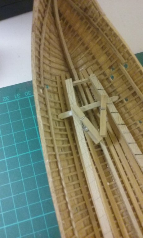
Thanks everything for the likes. Pat, thanks for the comment, though I'm afraid the frame to hold the oars is a modern fudge, as I'm not prepared to put in lower oar benches and oarsmen that will never be seen. Steven
-
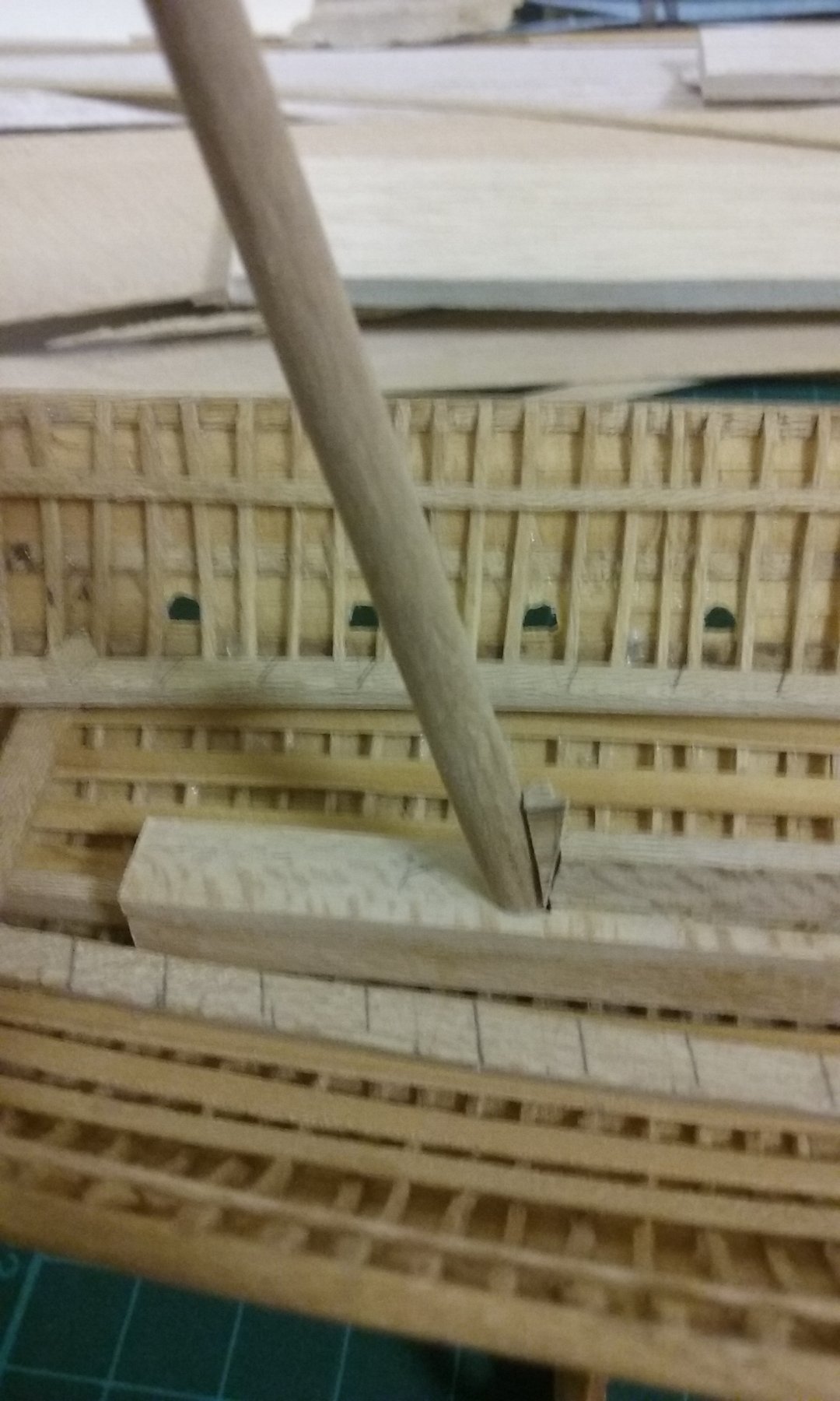
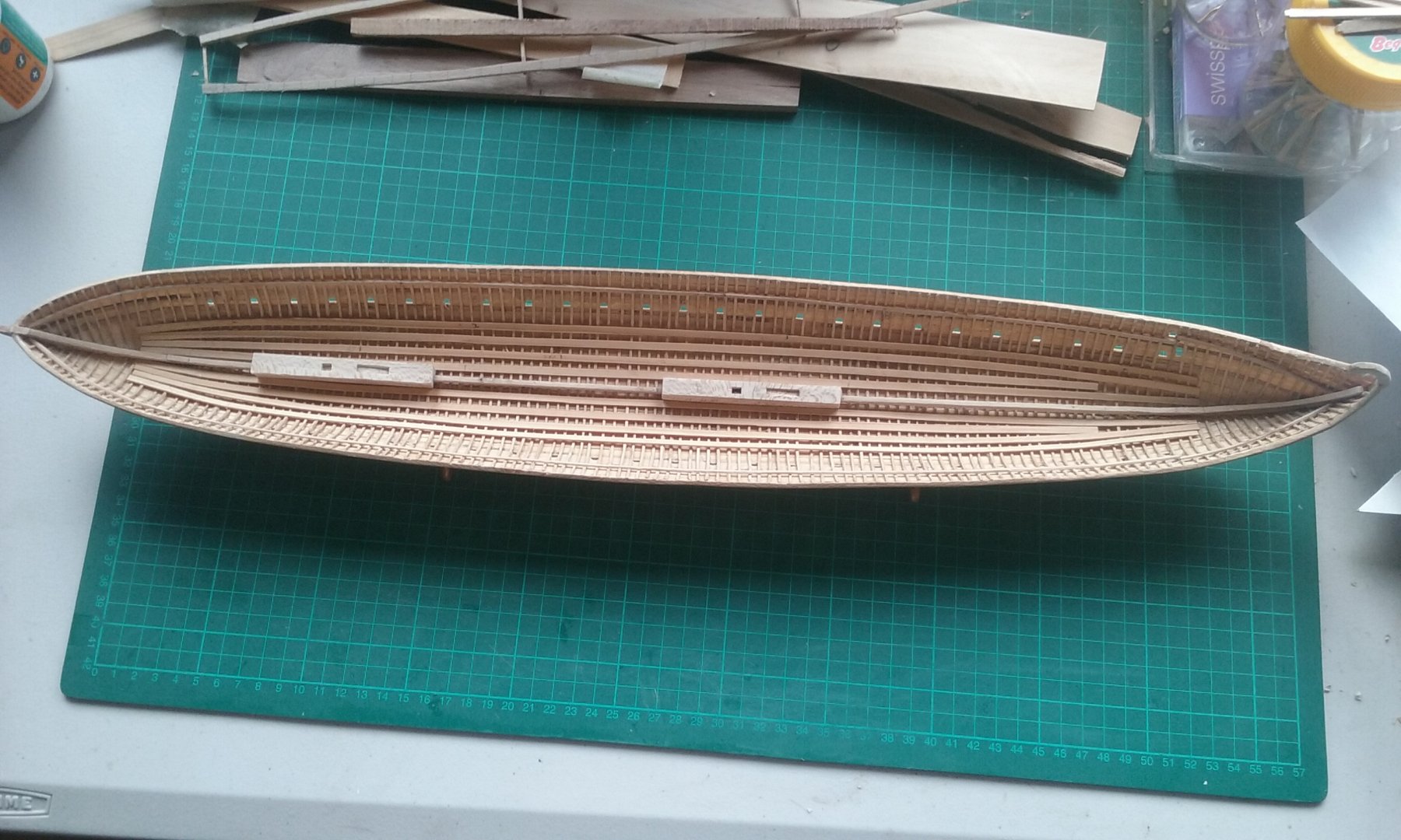
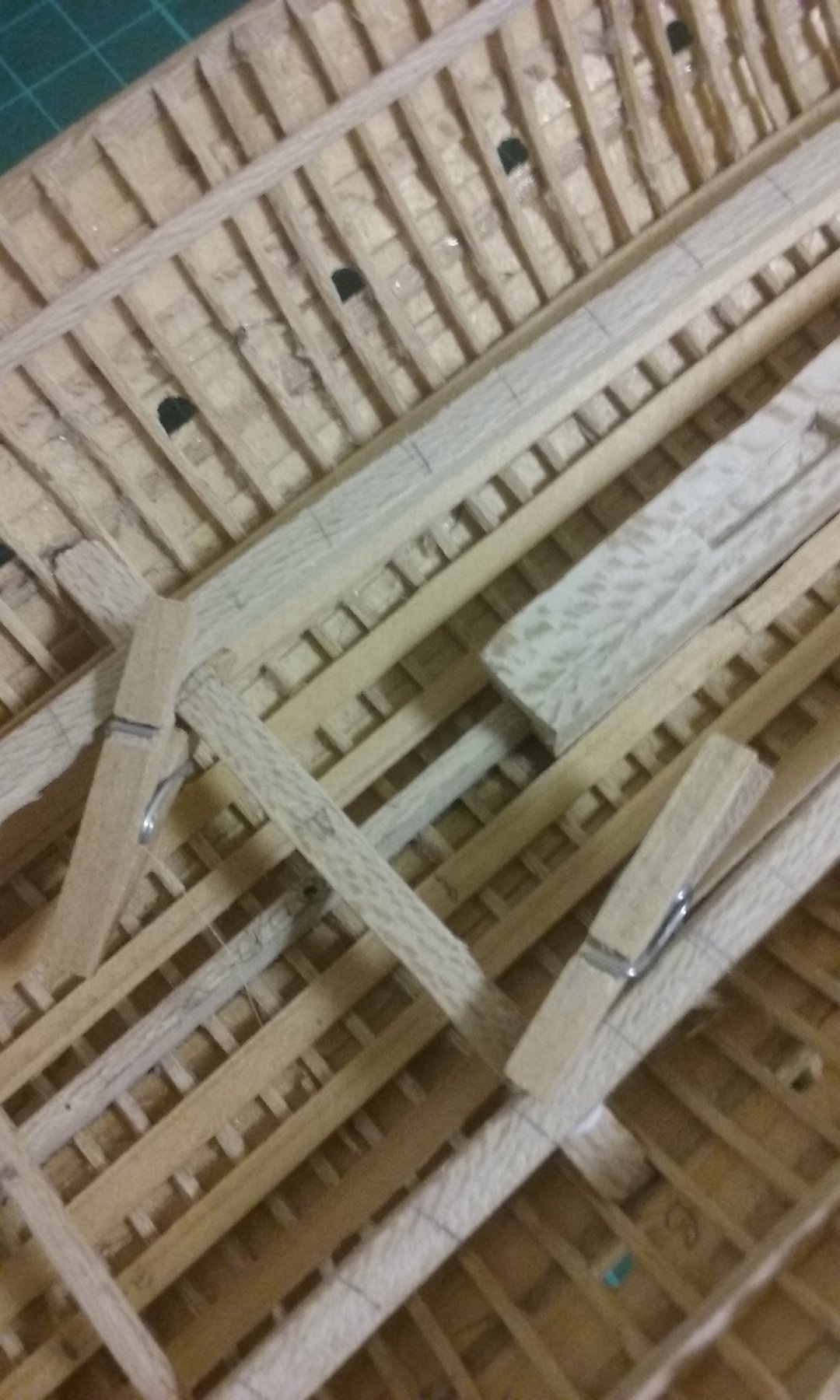
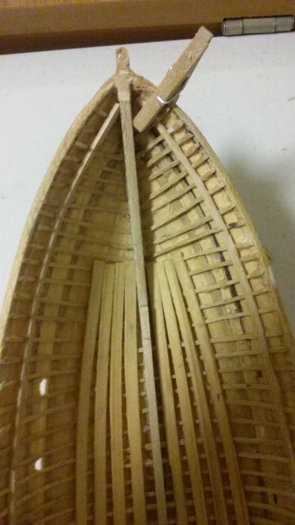
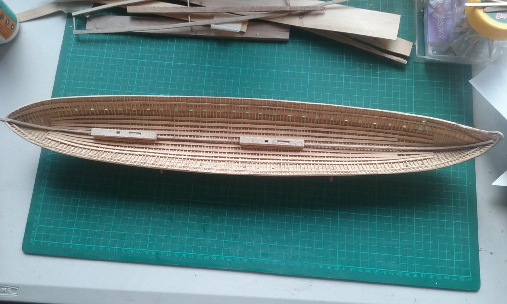
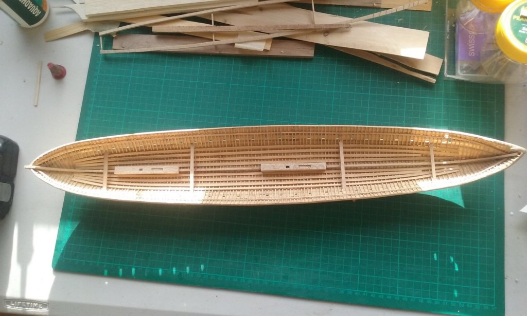
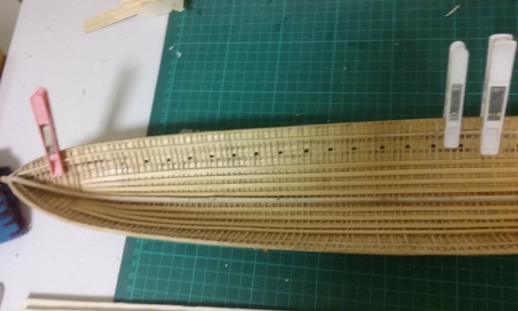
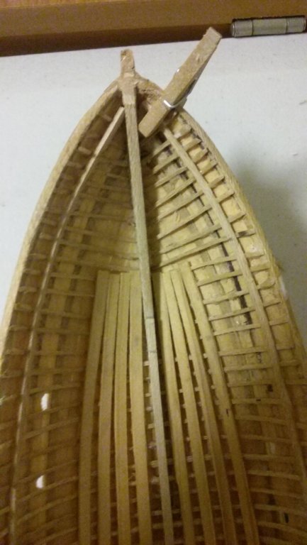
I've made the mast steps and put them in. Here they are dry fitted: The supports for the frame to hold the lower bank of oars are now glued in place: And the frame has been glued to them. Oops: I discovered that the pencilled guidelines I'd drawn to fix the angle of the oars faced 180 degrees the wrong way, so I had to erase them and redraw them. I still have a remnant of the wrong ones because I started with spirit pen at one end and couldn't get rid of it. As the pencil line around each oar where it goes through the oarport was getting faint I've also re-done the lines. And the mast steps are now glued in, along with the blocking pieces. Still working on the new masts and then I'll make the wedges to hold them in place. I also have to make and insert the mast partners to hold them rigidly. Steven


-
A very interesting framing system, Dick. Is this based on the Libro di Navigar? Steven
- 263 replies
-
- 2
-
-
- nave tonda
- round ship
- (and 2 more)
-
Yes, that's the Italian name for it, and the name of the republic of Ragusa from the 14th to the early 19th century. It's apparently where we get the name "argosy" meaning a fleet - not, as I'd thought, from Jason's ship Argo. A very nice body of work, GG. And the carrack is very finely done. Steven
-
Lou, to my chagrin I'd never heard of the Beaverford, which seems to me had even more to do with saving the convoy than the Jervis Bay, (noble though her sacrifice was). I looked Beaverford up and was astounded at her achievement - for an unarmoured merchant vessel to hold off a pocket battleship for 5 hours, with only a 3'' and a 4" gun. Amazing and incredibly courageous. And it's shameful they were never given official recognition. Steven
- 292 replies
-
- 5
-
-
- g class destroyer
- trumpeter
- (and 4 more)
-
Steve, that's a beautiful model of a beautiful vessel. With such high quality of workmanship it's hard to believe it's your first build. Steven
- 48 replies
-
- 3
-
-
- first build
- bowdoin
- (and 2 more)
-
Working on getting the beam shelf smooth. To be honest, the amount of wobble is pretty tiny - maybe 1/2mm - but it does make a difference. To smooth out the curve I've used all three techniques I mentioned earlier - slicing off where it was too high, filling where it's too low, and relocating the beam shelf where it's too far off the line to slice or fill. Still a bit to do before it's all smooth. Next time I do something like this I'll make sure I get it right first time so I don't have to get into this whole correction thing, which wastes time and effort. A lesson learnt (I hope!). Steven
-
Nice work, Patrick. I like the way you've fixed the guns. They'll certainly never come loose! (and as you say, the screws will be invisible). Beautiful detail work, as we've come to expect from you. Steven
- 756 replies
-
- 5
-
-
- galleon
- golden hind
- (and 2 more)
-
Carl, It looks like you replied while I was in the middle of editing my post above to add another photo and two links, which I hope are of help. Steven
- 292 replies
-
- 6
-
-
- g class destroyer
- trumpeter
- (and 4 more)
-
I feel the same way, Lou. The ABDA force didn't achieve their aim to stop the Japanese invasion. But they were a scratch force flung together from widely disparate navies with no opportunity to train together or work out a common strategy and tactics - not to mention the language problem! They knew they were outgunned and outclassed, but answered the call with heroism that is hard to contemplate in today's world. Not forgetting the Jervis Bay. https://en.wikipedia.org/wiki/HMS_Jervis_Bay Carl, try doing a google image search on HMS Glowworm - several of the photos that are fairly small in the above links can be found larger and with better detail by doing this. Steven PS: Just found another one! and links to higher definition photos - https://i.pinimg.com/originals/cb/1c/70/cb1c700a04541ee2356ef9efa0c5439a.jpg and https://i.pinimg.com/originals/48/84/69/4884695873e57a0ef98a10aaa8697b78.jpg .
- 292 replies
-
- 6
-
-
- g class destroyer
- trumpeter
- (and 4 more)
-
Just did a bit of a Google search for pictures of the Glowworm. There's some good ones at http://navalwarfare.blogspot.com/2009/06/hms-glowworm-h92.html https://wrecksite.eu/wreck.aspx?15989 and http://forum.netmarine.net/viewtopic.php?t=3502 (this one's in French, but Google Translate should help if needed - unless you're already fluent, of course. Zut! Alors . . .) and Russian . . https://u-96.livejournal.com/2670604.html with at least one photo the others don't have. Plus these two I hope these help. Steven
- 292 replies
-
- 6
-
-
- g class destroyer
- trumpeter
- (and 4 more)
-
Nice work, Javier, particularly at such a small scale. I suppose the skids on the bottom are to help run the boat up onto the beach (which is large flint pebbles, if I recall correctly). Looking forward to following your progress on this one. Steven
-
Thanks, Mark. But the shelf needs to follow a smooth curve to get the deck to be consistent, otherwise the deck itself will be all wobbly. Steven
-
Fascinating stuff, L.H. Steven
-
This wee sleekit cow'rin' tim'rous beastie looks forward to following the progress of your cunning plan. Steven
- 263 replies
-
- 2
-
-
- nave tonda
- round ship
- (and 2 more)
-
Beautiful work, Michael. A real pleasure to watch this build. Oh, and I take comfort from the fact that even someone at your advanced level sometimes misses something (the attachment of the vent stack). I don't feel quite so embarrassed about my own boo-boos. Still embarrassed - I've got a long way to go before I even approach your level of skill - but not quite so embarrassed. Steven
- 749 replies
-
- 7
-
-
- albertic
- ocean liner
- (and 2 more)
-
HMCSS Victoria 1855 by BANYAN - 1:72
Louie da fly replied to BANYAN's topic in - Build logs for subjects built 1851 - 1900
Very nice work, Pat. Steven- 1,013 replies
-
- 4
-
-
- gun dispatch vessel
- victoria
- (and 2 more)
-
Or a lot of rice. Off the subject a little, but still on the subject of measurement, an acre is an Anglo-Saxon measure of the amount of land that can be ploughed with a two-horse(?) plough in a day . . . (don't ask me about chains and perches and roods, let alone gills and bushels). And the values of measurement units differed from time to time and from place to place, such as the French, Dutch and English values for the foot. When they built the Olympias trireme reconstruction they used one value for an Ancient Greek unit (I think it was the cubit) but discovered in practice they would have been better using a slightly larger value from a slightly different time period, as there wasn't really enough room for the oarsmen (and women) to work the oars without interfering with each other. And the Byzantines had the same thing with their various measures - palm, finger, hand etc. They kept changing, making it very difficult for historians to work out the sizes things had been. Steven