Louie da fly
-
Posts
7,990 -
Joined
-
Last visited
Content Type
Profiles
Forums
Gallery
Events
Everything posted by Louie da fly
-
 Yes, I'd been thinking about that after seeing what you'd done with your round ship. Steven
 -
That's fantastic, mate. I'll be waiting with bated breath Steven
- 740 replies
-
- 2
-

-
- Tudor
- restoration
- (and 4 more)
-
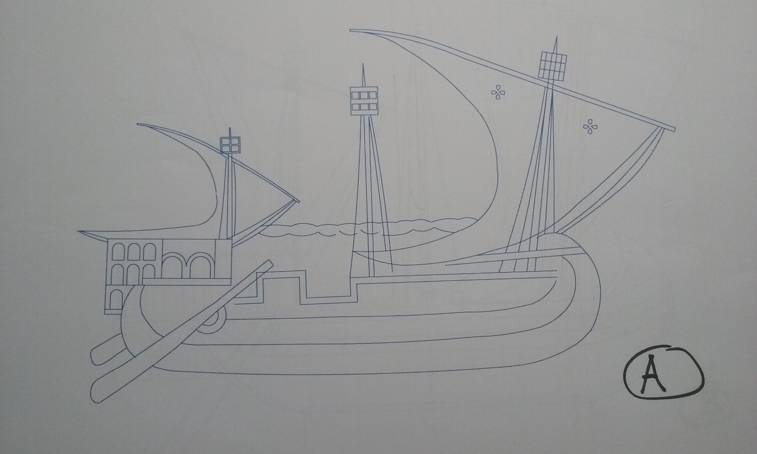
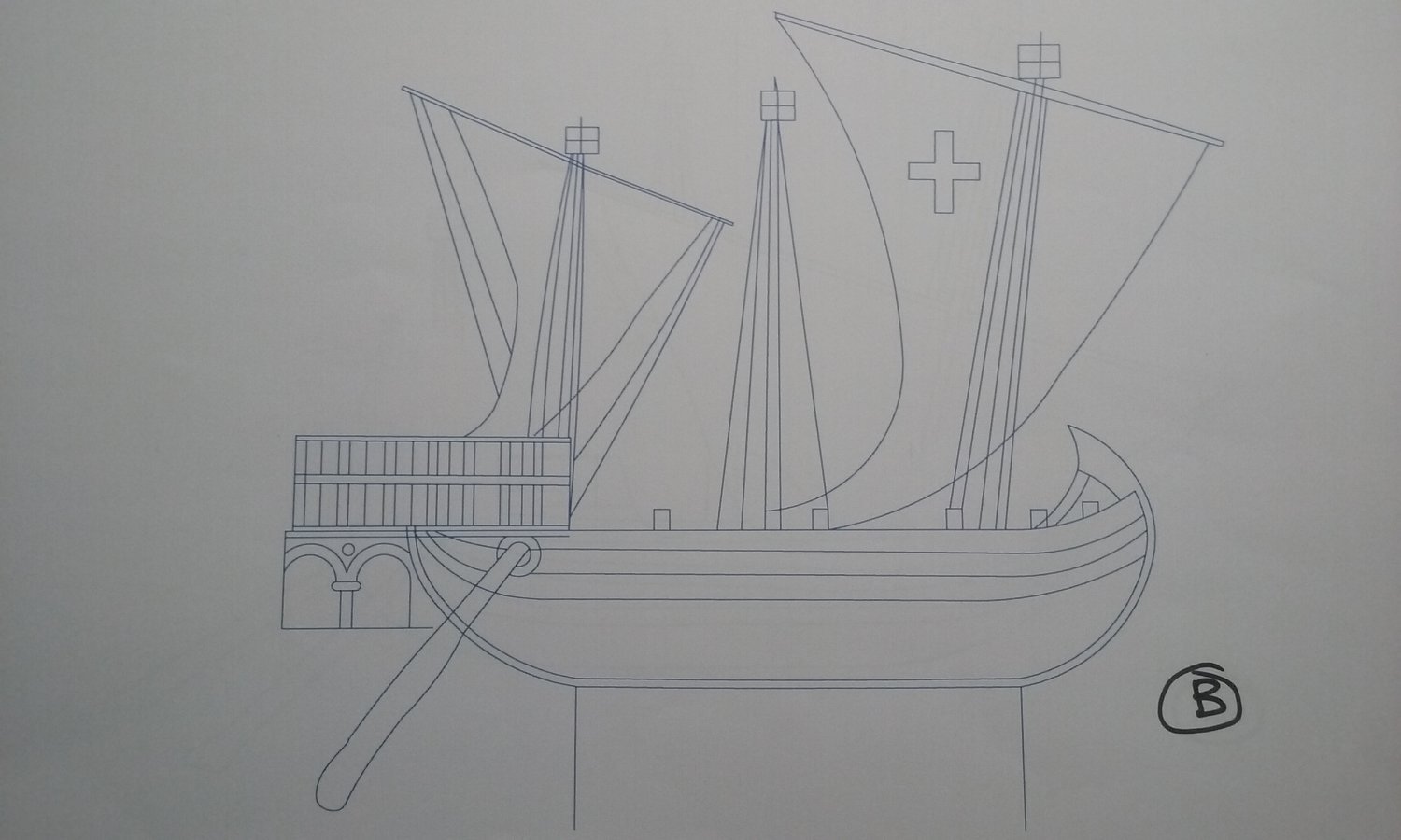
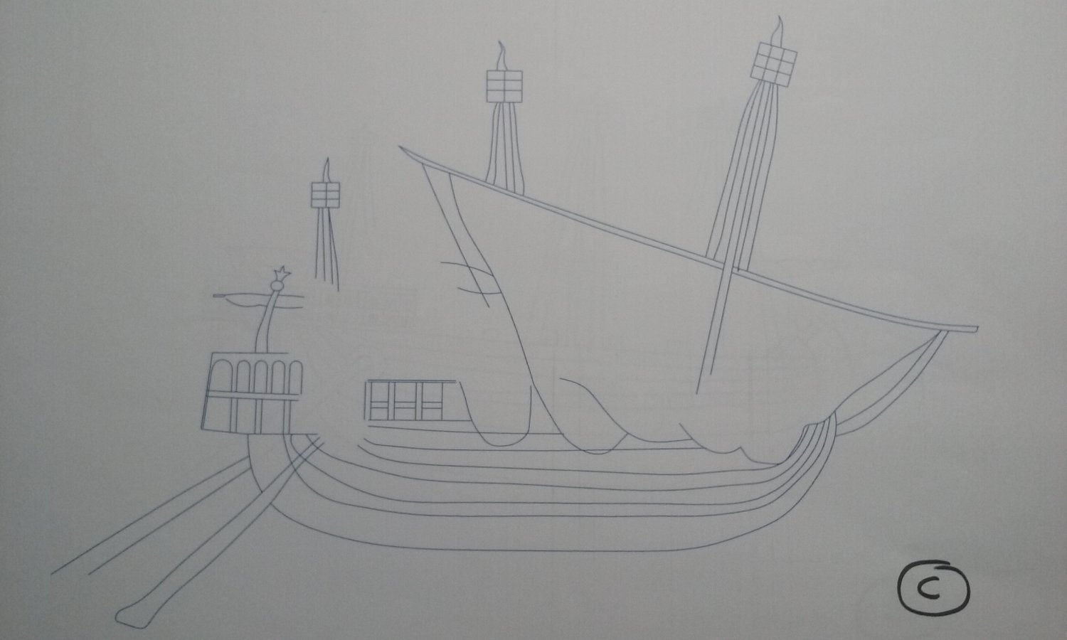
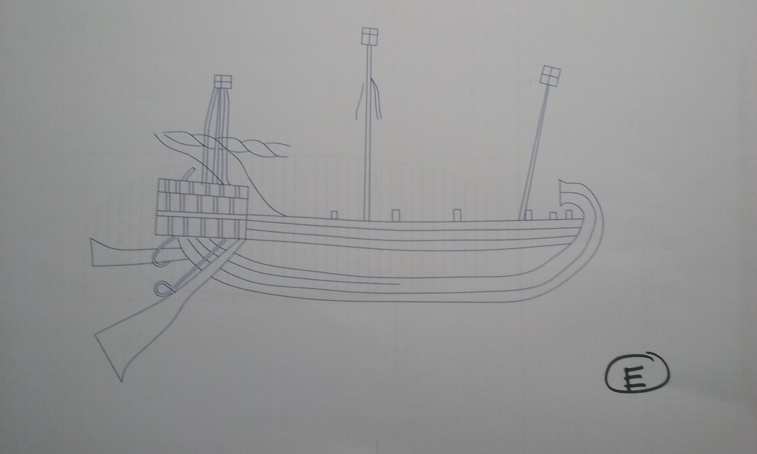
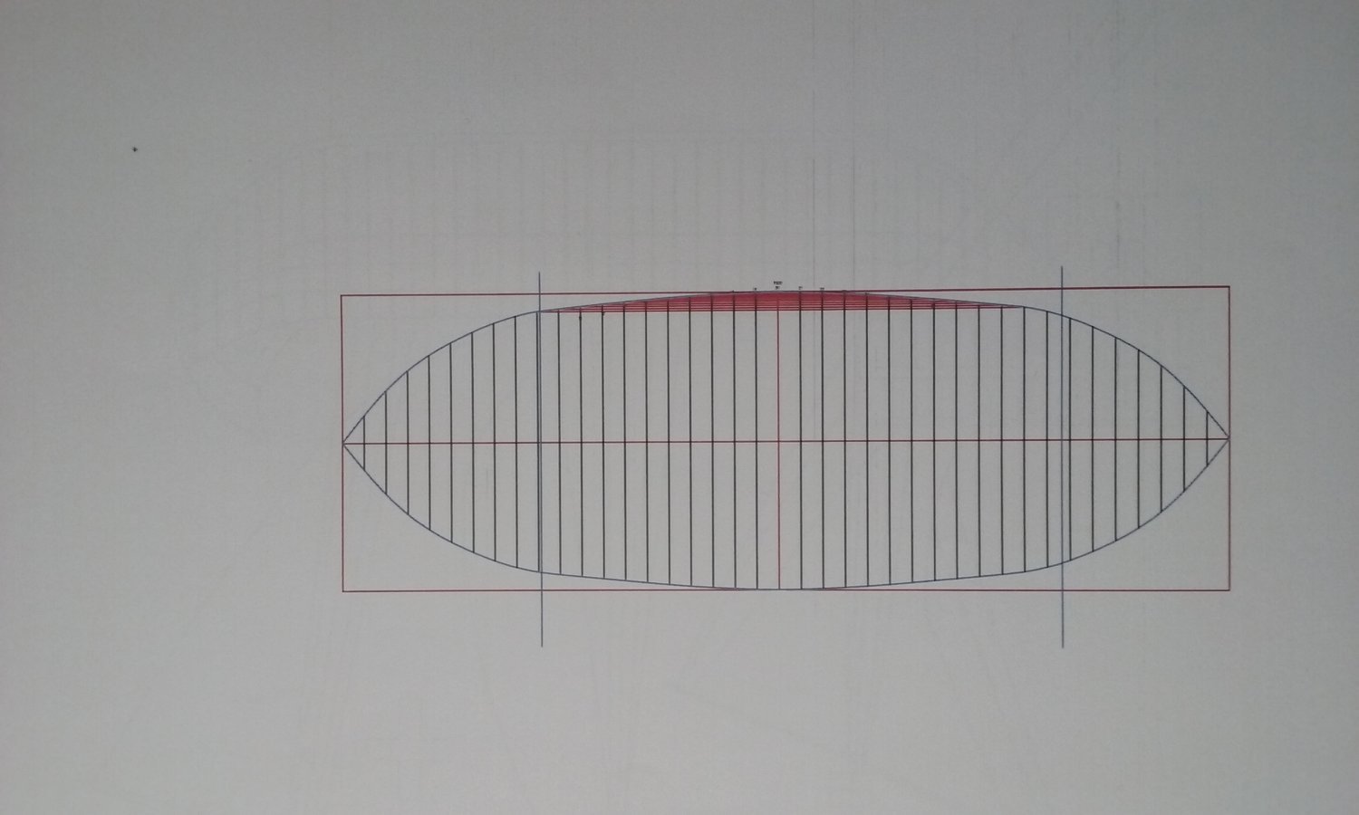
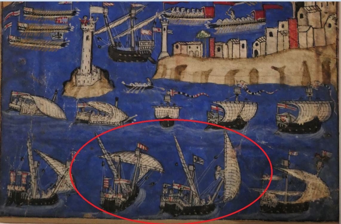
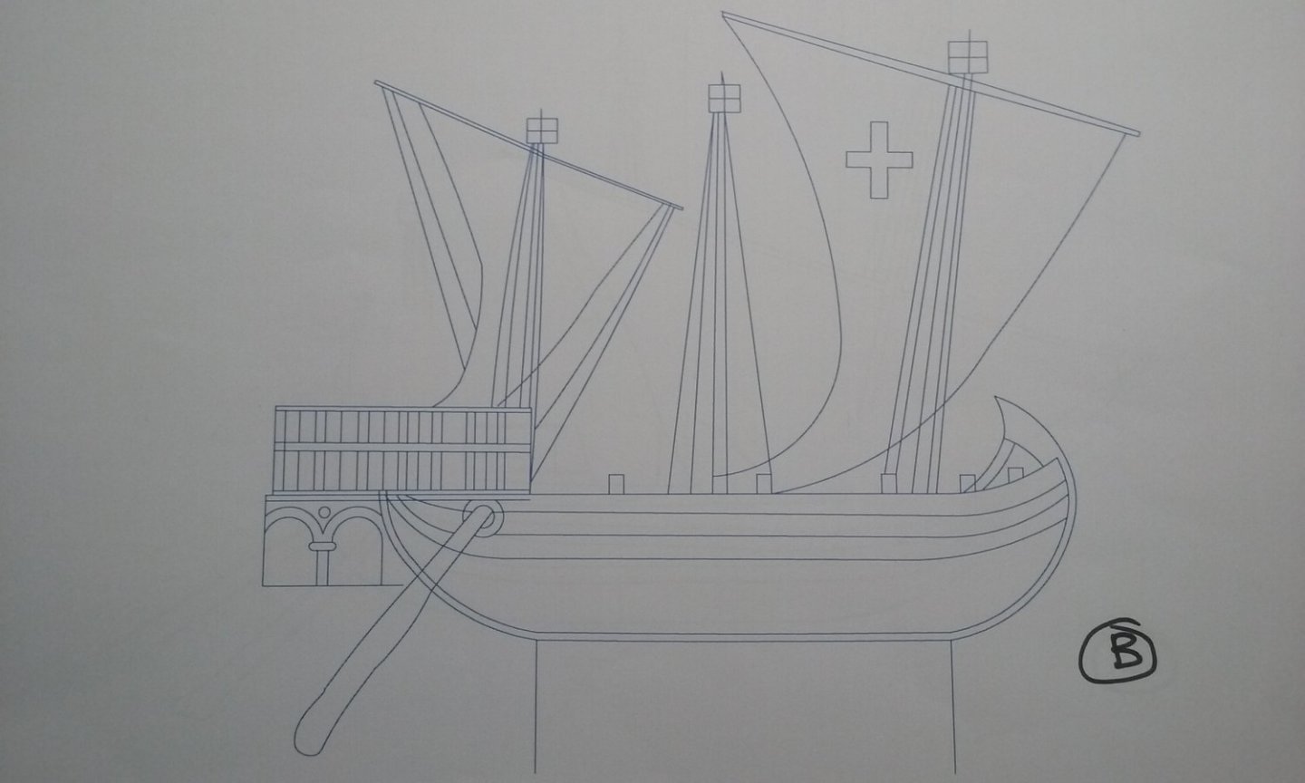
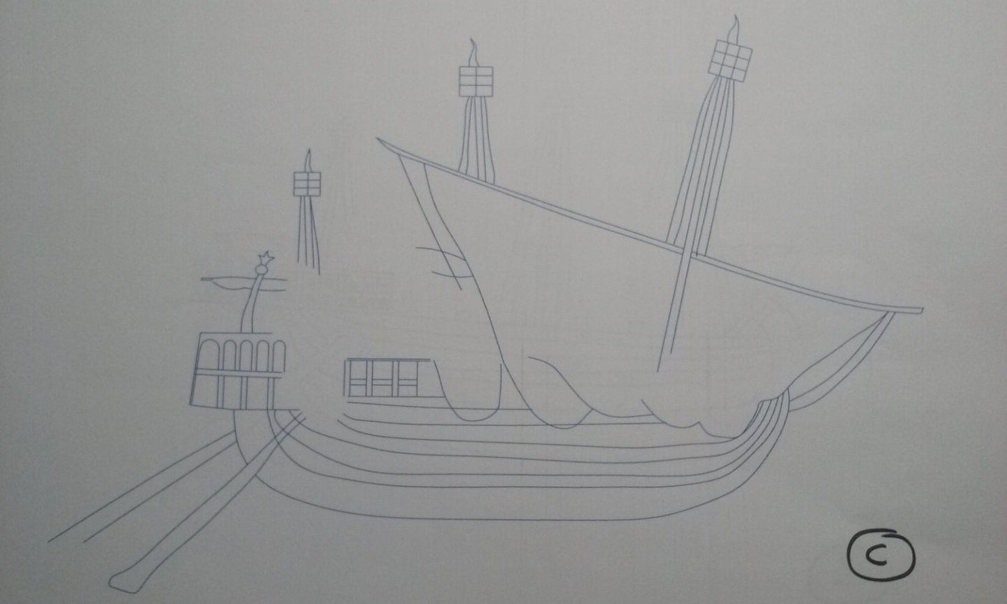
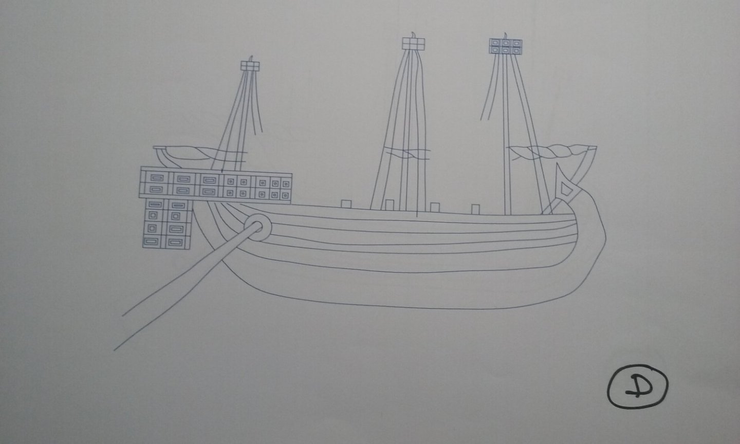
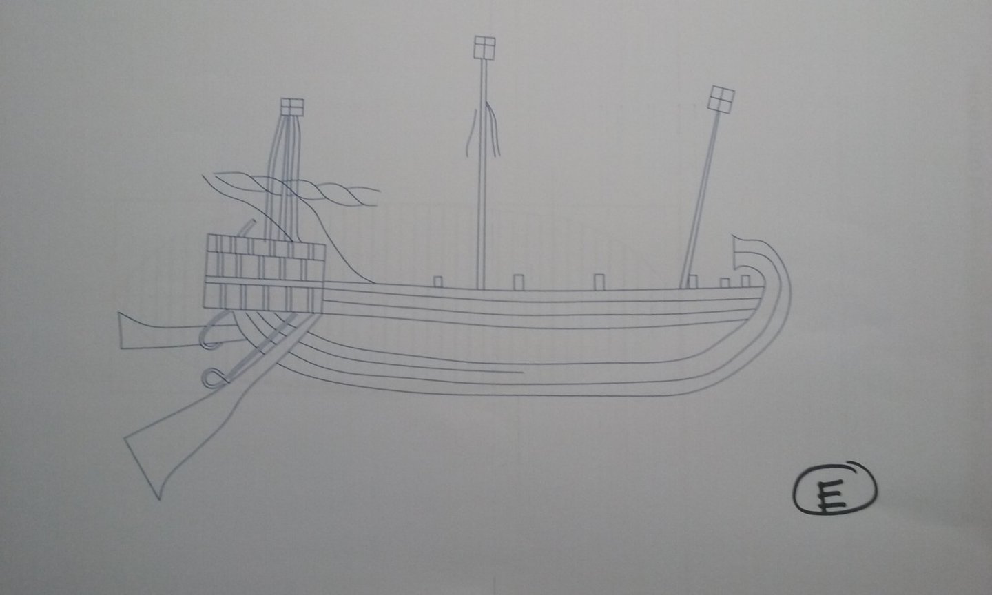
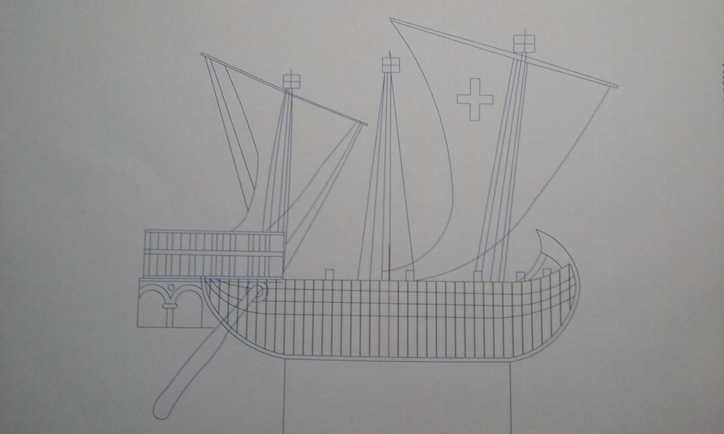
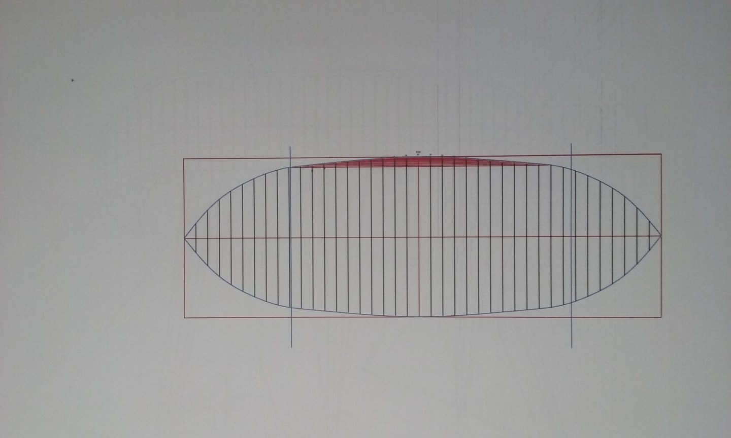
As I mentioned before, there are five representations of the same ship on the walls of San Marco, in a sort of cartoon strip telling the story of Saint Mark's body being rescued from destruction and smuggled away to its current home in Venice. The five depictions of the ship are very similar, but each one is slightly different from the others. To get a better handle on just what these differences are, and to get a "feel" for the ship itself, I took a leaf out of Björn Landström's book, by drawing them myself. But as we are now blessed with digital technology he had no access to in the 1960s, I was able to import the five mosaics into AutoCad and trace each one. Here they are: Note that there are gaps in the tracings. These are where there are human figures obscuring the lines of the ship. All the ships have three masts, evidently lateen rigged, with what appear to be lanterns (or tops?) at the masthead. In the two pictures where the sails are spread they are decorated - onewith a red cross, the other with two quatrefoils (four-leafed flowers). All are without a forecastle but wherever it's visible, the stempost curls backward. All have a "sterncastle", but each one is different. All have some sort of "fretwork", but in some it's square, in others arched. In B and D (and perhaps in A) there is a strange downward extension at the aft end. I have no idea what it is. All are shown with (usually two) side-rudders in the usual Mediterranean tradition, but the rudders are different shapes. E shows some sort of tackle for controlling the rudders, and has the larboard rudder swivelled upwards. B and D show only a single rudder, but I believe it was simply omitted from the mosaic, not that it represents the ship having a single rudder. A, B and D show the rudder shaft going into the hull through a circular hole. This is mentioned in what is pretty much the definitive study of rudder evolution The Development of the Rudder A.D. 100-1600 - A Technological Tale by Lawrence V. Mott, but after discussion with Woodrat I've come to agree with him that this is not in fact a practical way of hanging a rudder and must be a result of artist's error. Probably the thing that finally convinced me was looking at the Cocharelli Codex again and discovering that though ships are shown with this feature in a side view, in a stern view it is evident that they are supported outside the hull, from the "sterncastle". B, D and E have what might be described as cleats sticking up above the gunwales, and in the mosaics they have loops of rope belayed to them (see the second photo in my first post above, though the loops are a bit hard to see). Whereas A has a sort of "battlemented" side. Two mosaics (C and E) show "wings" at the stern, a common feature of Mediterranean ships of this period. I've used the Mezza Lune technique to work out the shape of the hull (thanks, Woodrat!). These calculations relate only to the floors - that is once the stempost and sternpost curve up from the keel it no longer applies, and you have to work out how to curve the hull inwards from there to the bow and stern. You can see on the plan view the lines that show the extent of the floors. and the last pic shows how the frames line up with the hull in B. Now I have to reconcile these five pictures and choose which features I'm going to go with - or perhaps choose a single mosaic and just go with that one. Steven

-
Brilliant as always, Greg. I'd like to sit at your feet as you weather your models - amazing! Steven
-
Oh, yes. I'm a big Pratchett fan, too. Have you seen the short movie of his short story "Troll Bridge", starring Cohen the Barbarian, made here in Oz?
-
Making very good progress, Norseman. Most people seem to have trouble with the planks - not sure if it's a fault in the kit or just the way it goes with such a complex shape. I think you're right to try making your own rudder fittings. Plywood really isn't suitable for something like that. Steven
-
I'm glad you're getting it sorted out, Rudybob (having had enough problems myself with the same thing). I think Gregory's most recent post explains the issue very clearly. Steven
-
Naval History On This Day, Any Nation
Louie da fly replied to Kevin's topic in Nautical/Naval History
Not on this day, but I couldn't find any other section to put it in, and I think it's worth seeing.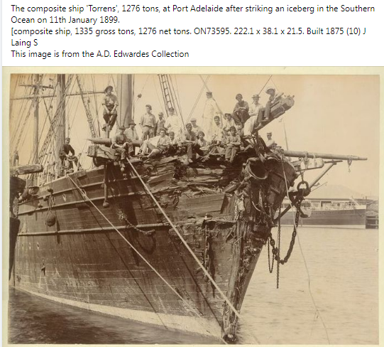
-
I totally agree. Not only henry, but over the years I have had so much generous unselfish help from many MSW members which has been invaluable to me. This is a pretty special forum. Steven
- 740 replies
-
- 6
-
-
- Tudor
- restoration
- (and 4 more)
-
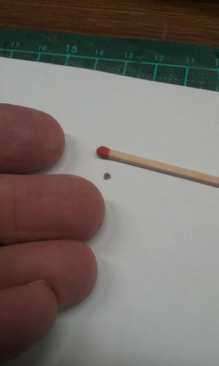
Thanks everybody for the suggestions. Fortunately it looks like @henrythestaffy is coming to the rescue by 3D printing a whole bunch of them for me. My heartfelt thanks, mate. And this is the reason I'm having so much trouble making the deadeyes out of natural materials: That deadeye is 2mm on each side. I haven't been able to make any myself that are smaller than 3mm. And keeping in mind that those three holes have to be big enough for cotton thread to fit through . . . Steven

- 740 replies
-
- 9
-
-

-
- Tudor
- restoration
- (and 4 more)
-
Just to answer a question several of you have asked, the grain orientation is up and down or side to side (depending on which way up the deadeye is), not front-to-back. I think that would be an even worse invitation for the wood to split. Steven
- 740 replies
-
- 2
-
-
- Tudor
- restoration
- (and 4 more)
-
Hi Keith, I tried that. Really not as satisfactory. Steven
- 740 replies
-
- 2
-
-
- Tudor
- restoration
- (and 4 more)
-
Thanks everybody for the reactions, and suggestions on how to fix it. Baker and Druxey, I really think that wood isn't capable of this kind of job - I don't have any boxwood so I don't know its grain would be fine enough, but I think it would be the only wood suitable - and maybe even that wouldn't work. I've tried pear wood and it splits as well. I've tried card impregnated with white glue and it works better, but still not really all that wonderful. Don't worry, I'm not going to do anything drastic until I have a better solution, but I really think the current deadeyes have to go. Liteflight, I've never heard of Paxolin. Where do you get it in Oz? I don't think the birch would work any better than what I'm using, but I have considered the hot needle method - just a matter of practicality; over 100 deadeyes each with 3 holes, without burning my fingers . . . Henrythestaffy, I'm sending you a PM. Thanks again, everyone. Steven
- 740 replies
-
- 3
-
-
- Tudor
- restoration
- (and 4 more)
-
Yes, it's a fair bit of work and needs quite a bit of thought. I certainly don't regard myself as an expert (and I still make a lot of mistakes). But it does make a nicer looking model in the long run. And of course, experience is a great teacher. Steven
- 77 replies
-
- 3
-
-
- Santa Maria
- Artesania Latina
- (and 1 more)
-
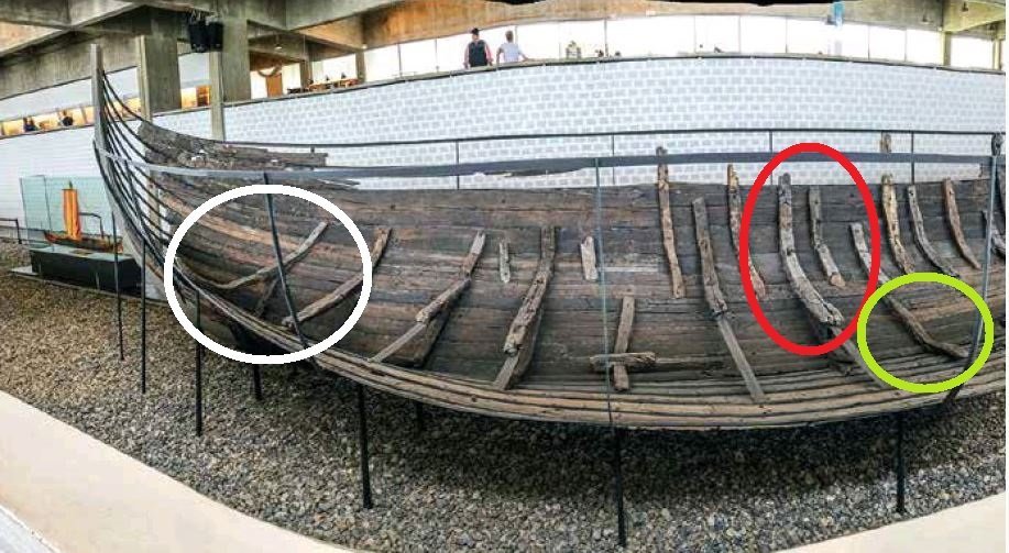
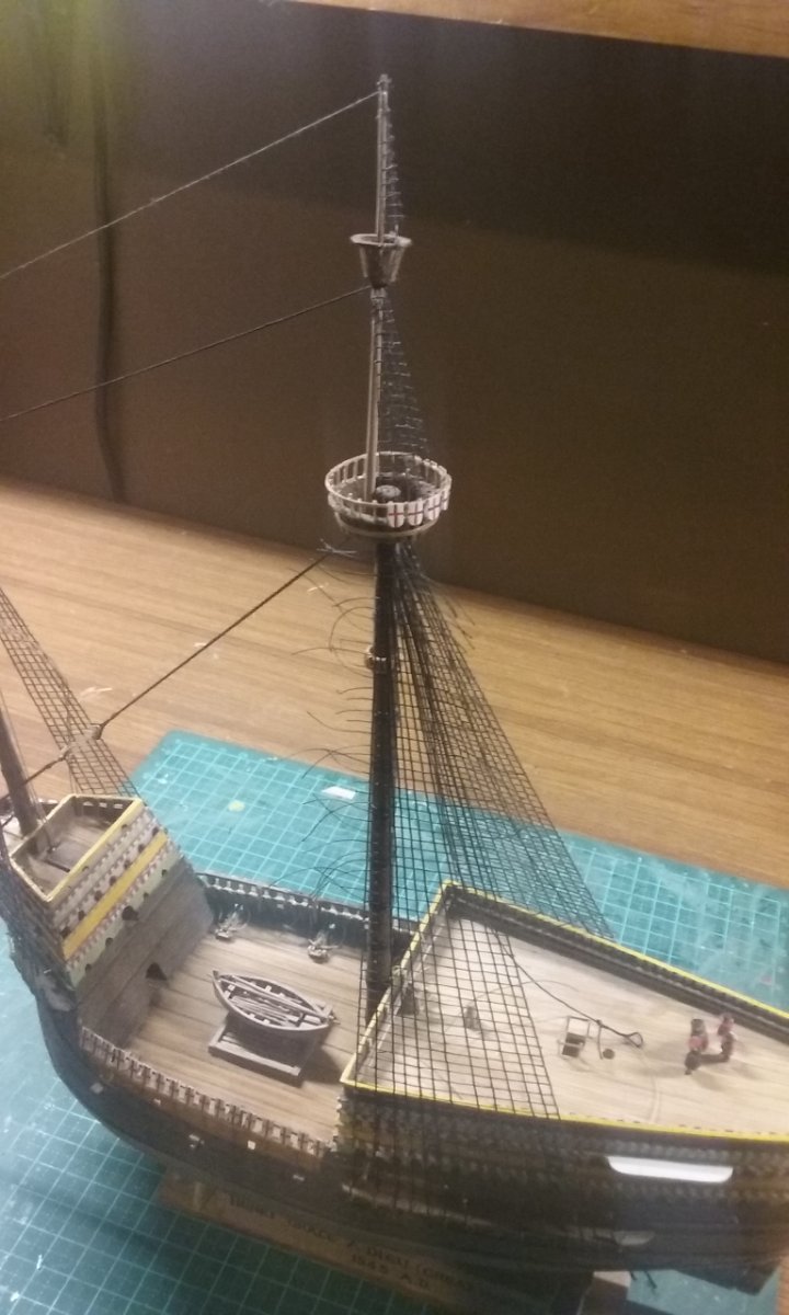
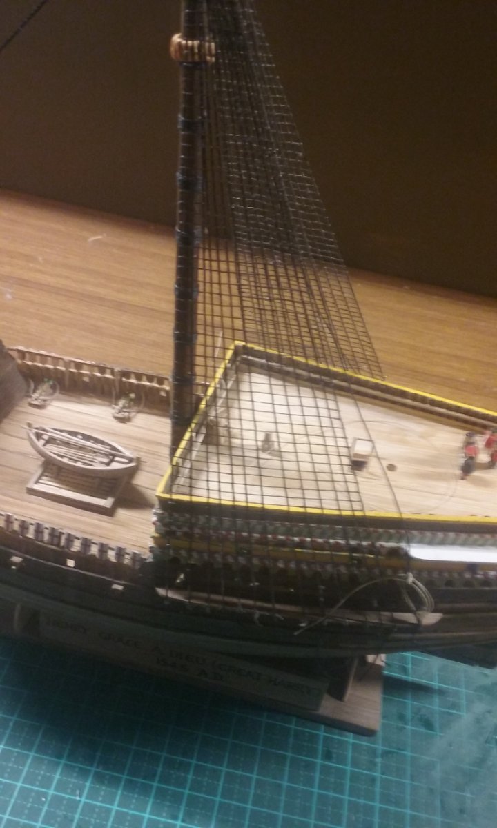
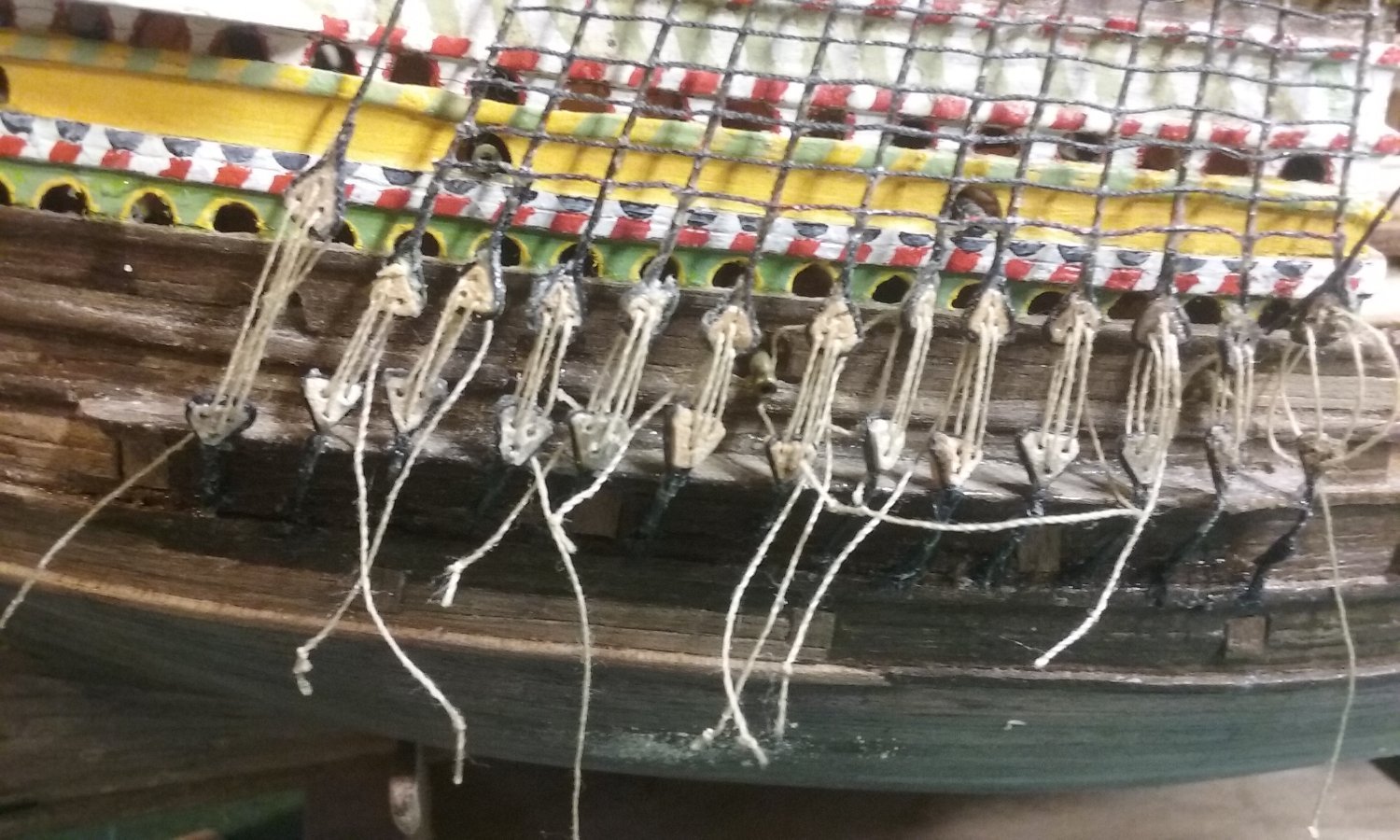
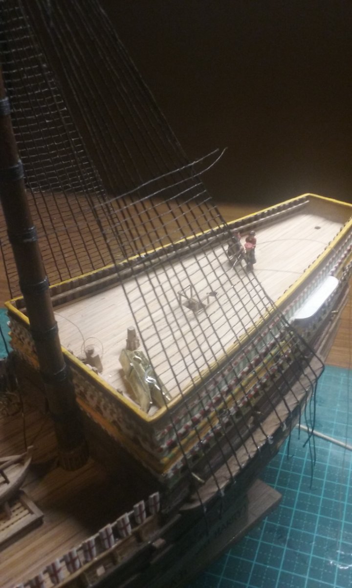
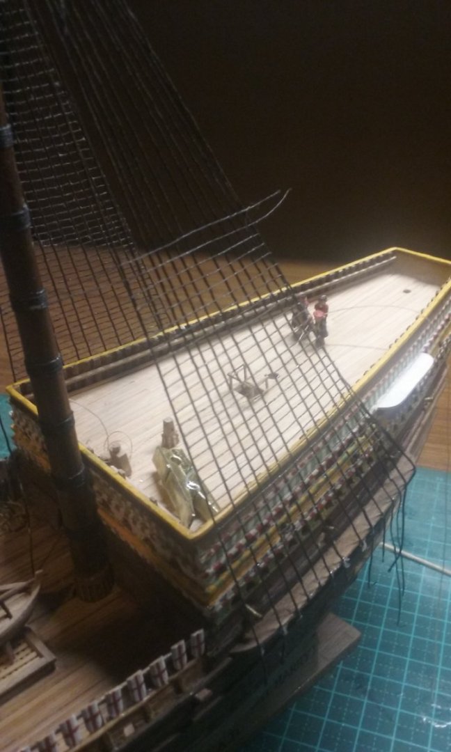
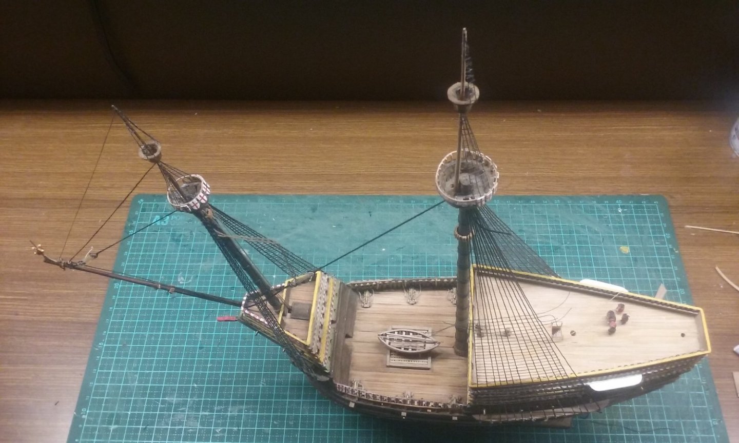
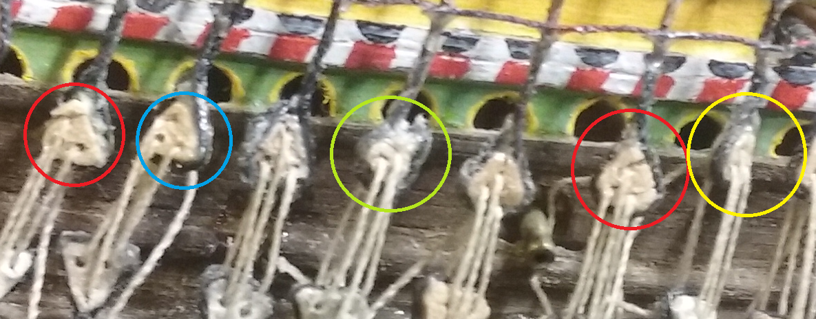
Some good news and bad news. First the good news; I've finished adding the ratlines on the larboard main shrouds. In progress: All ratlines in place but before trimming After trimming Now the bad news - the main starboard deadeyes really aren't working. They're all over the place, some of the deadeyes themselves have broken (red circles below - they're made of wood), they're different sizes, different distances apart, some twisted (yellow circle), the holes have pulled through so the lanyards terminate in the wrong places (blue circle) - and I have no idea what happened in the green circle. Add to that the fact that some of the lanyards got glued into the holes so I couldn't pull them tight. Gak! I think I really need to re-examine all of these, probably rip them all off and start again doing it differently. I've started experimenting, but not having a lot of success so far. Steven


- 740 replies
-
- 11
-

-
-
-
- Tudor
- restoration
- (and 4 more)
-
Hi Masa, your first planking has turned out very nicely, and the sanding has produced a nice smooth shape. But it might be worth knowing that the planking method (which I think is per Artesania Latina's instructions) isn't how it was done in the real world. There are some planking tutorials here: which show how it was done on real ships. At this stage, as you've got a very nice hull shape from your first planking, you have an opportunity to do your second planking more realistically if you choose to do so. It does take more work, but in my opinion the end result is worth it. However, this is your model, and it's your decision. Either way, you'll have a very nice looking model. Steven
- 77 replies
-
- 2
-
-
- Santa Maria
- Artesania Latina
- (and 1 more)
-
Good to see, mate. I'd thought of doing a Sophie myself at one point but never got around to it. There's a wealth of information about her in Master and Commander as I'm sure you already know. Good to see you've got it happening.
- 346 replies
-
- 2
-
-
- Sophie
- Vanguard Models
- (and 1 more)
-
My own nef was built plank first over a wooden mould or plug, but I have to admit I did find it difficult to get it exactly symmetrical, and frame first would be better in that respect. Steven
-
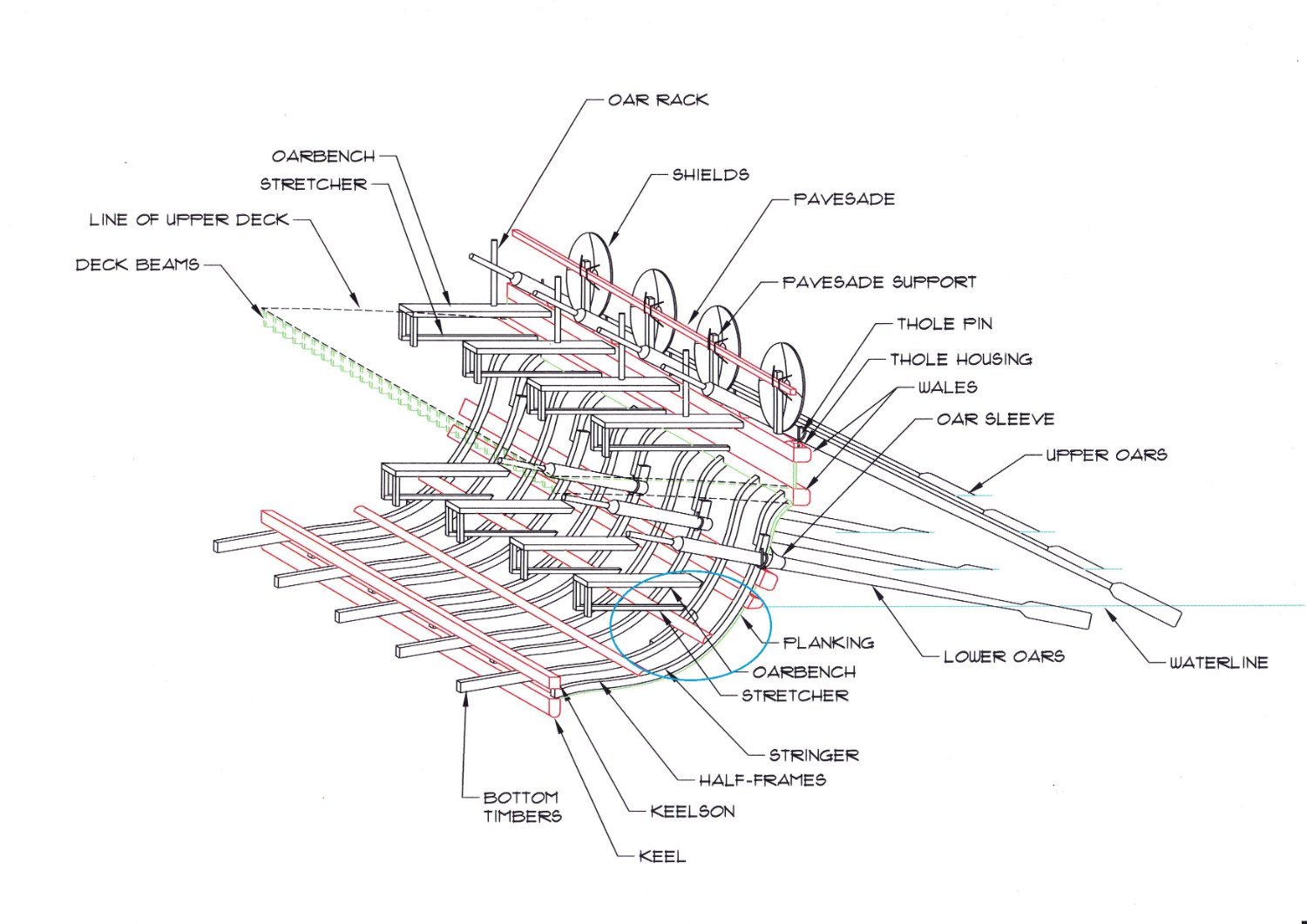
Just be aware that I changed my mind about the frame construction partway through, and started making them a completely different way - see post #158 and #166 in my build log. The hefty through-beams and the deck-beams help keep the hull shape, compensating for the weaker construction method, as you can see in post #171. You could probably assemble each of your frames as a unit consisting of the floor-timber, the futtocks and the deck-beam, which would add to the rigidity of its construction (strictly, the deck-beams should rest on the beam shelf, but all of that would be covered by the deck anyway, so it would be invisible). Keep in mind that these ships almost certainly were built planking-first, not frame-first - the planking was put together then the frames were added. Frame-first construction was a later development. But unless you've got your wits about you, plank-first construction has a tendency to "squeeze" inwards resulting in a narrower vessel. There's nothing to stop you building yours frame-first - in fact there's a lot to be said for it, for consistency and symmetry and getting the hull-shape right. Steven
-
Oh boy. I hope we're not making your life too hard for you . . . Steven
-
Yes, sort of plywood if you like. But of course each ply should be half the final thickness of the frames.
-
Thanks for the comment, Roger, and to everyone for the likes. I just looked at the date on the first page of this log. It's taken me over 6 years to get to this stage (though on further inspection it appears I had a gap of two and a half years where I did nothing on it. Don't feel quite so bad about it . . .) Steven
- 740 replies
-
- 3
-
-
- Tudor
- restoration
- (and 4 more)
-
I'd second Druxey's advice. It'll save you a lot of grief down the line. If you have a look at the archaeology, you'll find that the frames at this time were usually not continuous, but instead made of several separate futtocks, often set side by side and overlapping rather than being joined in one continuous line, as in this diagram of a dromon's framing (circled in blue) and a different layout but with similar characteristics from the knarr Skuldelev 1 Steven