


Thistle17
-
Posts
1,042 -
Joined
-
Last visited
Content Type
Profiles
Forums
Gallery
Events
Posts posted by Thistle17
-
-
Thistles were a bit more pricey as I recall and I think that held them back here. I remember as at the time I could not afford one. i just looked up any clubs in the area and all I see is around Albany, Saratoga area.
Joe
-
Just discovered your work on this great model you are building. Brings back memories of an earlier time when Lightnings and Comets raced on Irondequit Bay in upstate NY. Don't see too many these days. Wonder why. Always admired the lines.
Joe
- Andrew J. and Roger Pellett
-
 1
1
-
 1
1
-
Model building is a series of problem solving steps isn't it?
Dziadeczek and Mark I appreciate the inputs on blackening since that is something new to me. I will try out a sample, solder and all, before I commit the ones planned for the model. and thanks for the warning about the blackening agent migration. and cleaning. Yet further considerations.
rraisely I did try automotive striping tape i had but it didn't stick well that is why I abandoned it. It was pretty old tape so likely the adhesive was dried out. .
Joe
- mtaylor, thibaultron and Keith Black
-
3
-
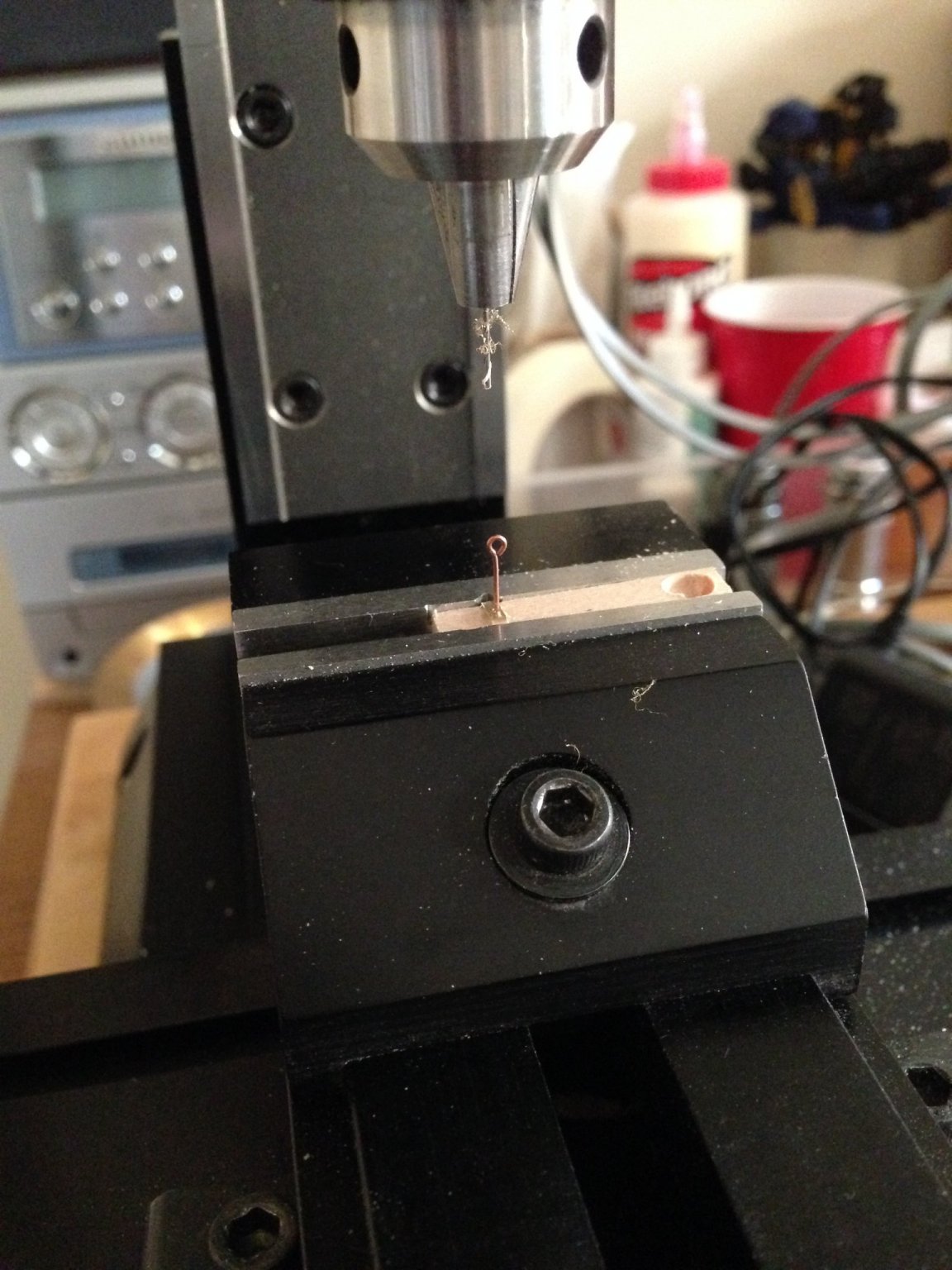
I am always grateful for the advice i recieve on this site so don't judge me too harshly in that I didn't use any of the techniques. This task has sat idel for 2 weeks as I was consumed by other non modeling needs and in that time one of my PC artwork mast bands started to lift. in that interval the 1/16 X 1/64 strips arrived. and those two events prompted me to try the brass approach once again.
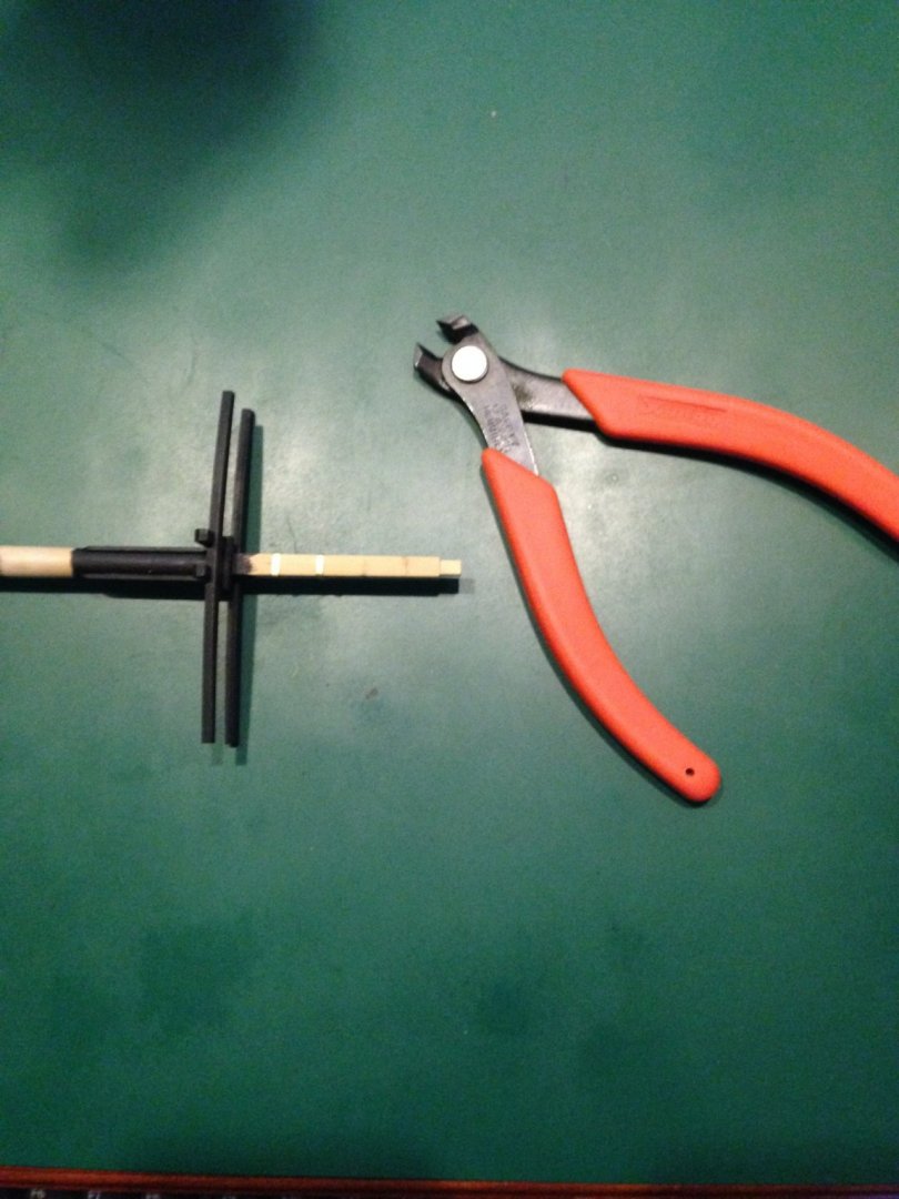
After stripping the mast bands in place I cut stock about 1 inch in length and marked the center. Laying the strip on the square mast section I carefully bent it into a "U" around that section. Naturally the bends form a slight radius. So I clamped the "U" in a square sided pliers and lightly hammered the corners to be a bit more square. The lower two bands were then wrapped around the front of the square section and trimmed with a railroad rail cutter. These I then soldered using one of the SMD (PC circuit surface mount device) solderering stations to complete the wrapped joint. It took a couple of tries but ultimately the fit was near perfect.
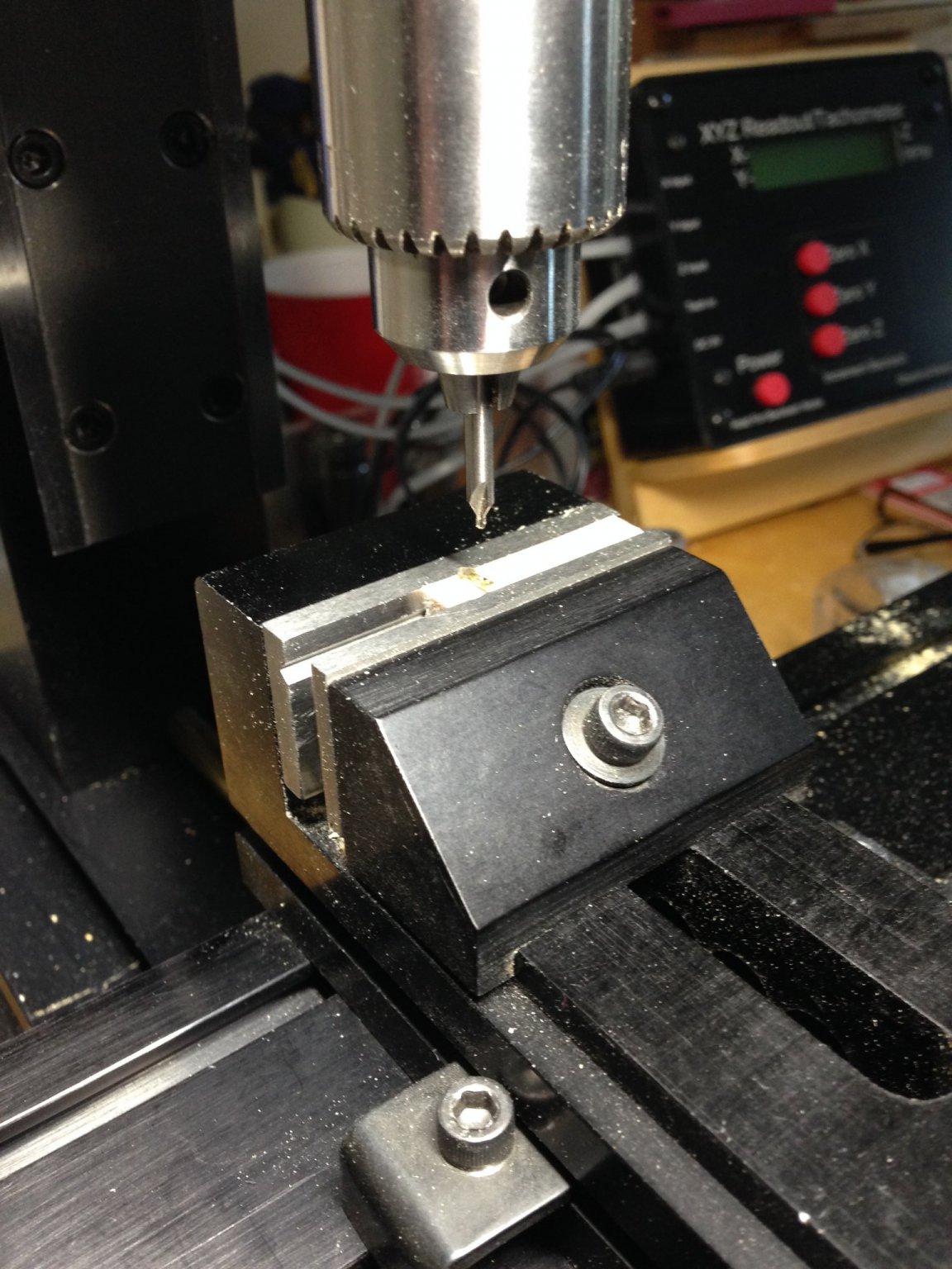
Just one problem remained. How was I to provision for an eyelet in the band for the gaff rigging! It occured to me that I just might be able to predrill a centered hole in the band for the eyelet prior to completing the full wrap. Using my mill Using my smallest center drill I had I just started the hole for a guide. I had my doubts about being able to accurate drill a hole but to my delight it worked. I will CA the eyelet into the band hole after installing and securing the band(s).
Just one problem left though. I need to blacken the bands and never having had expeience with the solution I remain in discovery mode. At this time i wonder about the solder residue. It is not likely to blacken. I anticipate i will still need to paint the bnds.
Joe


- mtaylor, Keith Black and thibaultron
-
3
-
I note from the date interval of your postings that things still may be a bit hectic for you on your outside duties. I have to believe this is an escape for you.
You were a subject of conversation with the NJ modelers group last night. The highlight speaker failed to show so Ryland brought up the 2014 NE Conference pictures and there you were! You make such an impression with your modeling everywhere.
Joe
- FrankWouts, Ryland Craze and Rustyj
-
3
-
Jim I am of the same mind. I can't imagine putting my name on this as "my" creation. It should be the original modeler. just yesterday i spent some time removing elements that are not attached to see if there was any trace of a name. None could be found. So it will remain a mystery for some time to come and hopefully not forever.
I still await the Smithsonian drawing for more detail information but as I inspect the model, ever more closely, I have begun to think that the builder may have known more of the vessel that the drawing may reveal. Some of the detail elements of the build are so subtle that a drawing may not have been enough of a reference.
The president of the Niagara Ship Modelers (Canada) relates that he adds a pull out on the bottom of his display cases indicating any information he wants to convey. All that I may do is have a plaque made for direct display indicating the vessel type, scale and builder as unknown and use the other technique for additional information.
Joe
- Ryland Craze and thibaultron
-
2
-
Roger thanks for the encouragement. yes she does not need a lot of work. However I am a bit tenuous regarding the restoration. I further note who ever did this was a master at controlling glue! It is just another sign of the competent nature of the creator. And you are right the case will be most of the work. Right now I am debating with myself of how to present her. I have some beautiful mahogany and cherry stock that I could use for a fully framed case. But I waver. It may be too elegant for a workboat? Should it just be a frameless cover and work a more fitting base into the design. I have to sleep on it a bit more.
Joe
- thibaultron and Ryland Craze
-
2
-
Thanks Jim I did discover this recently but have yet to download. I might mention I was also alerted by the secretary of the NRG that one can establish an ALERT on Google for any subject of interest that will do just that as related information is posted. I plan to use this as well.
Joe
- thibaultron and jlefever
-
2
-
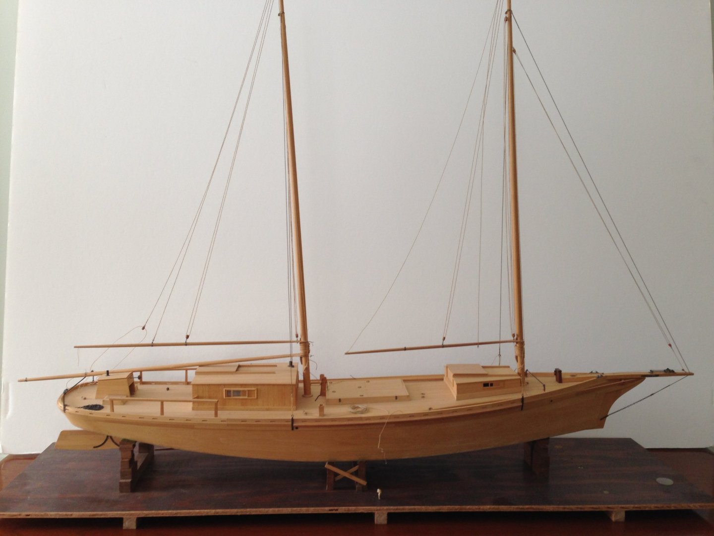
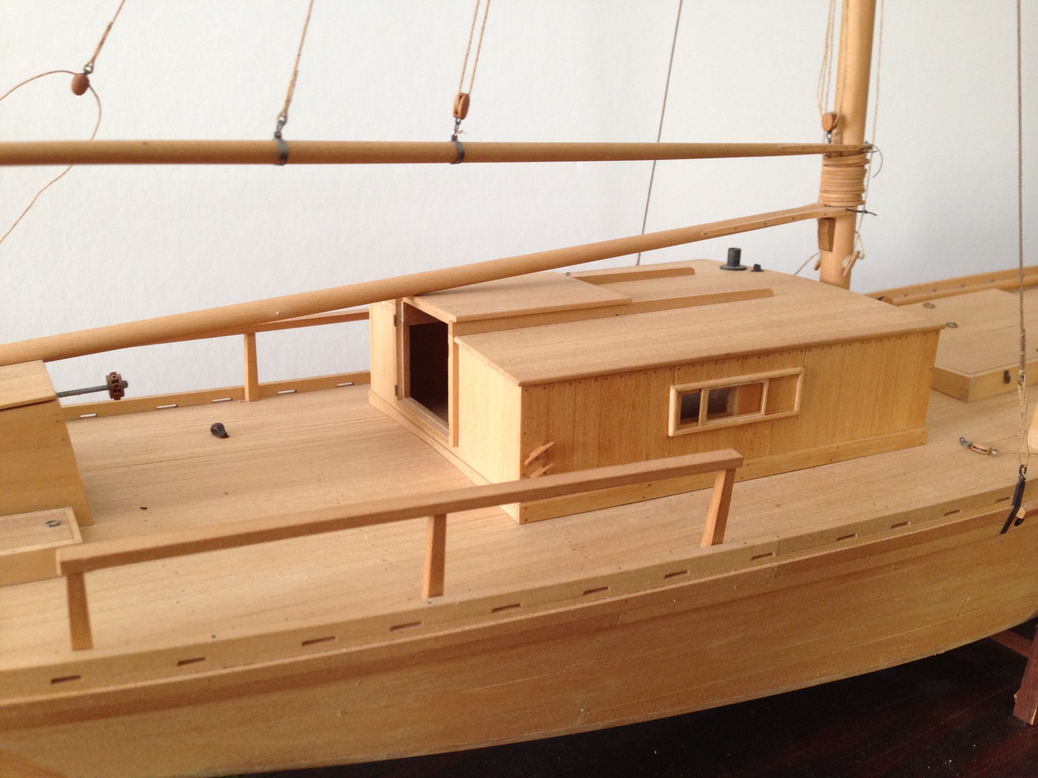
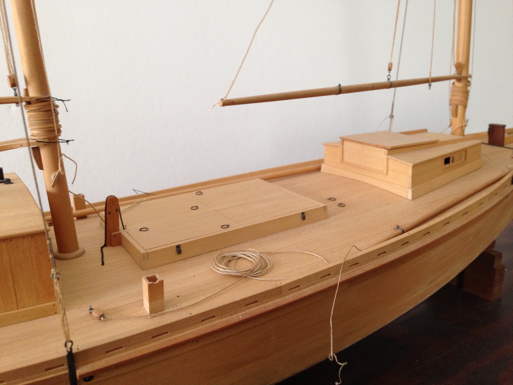
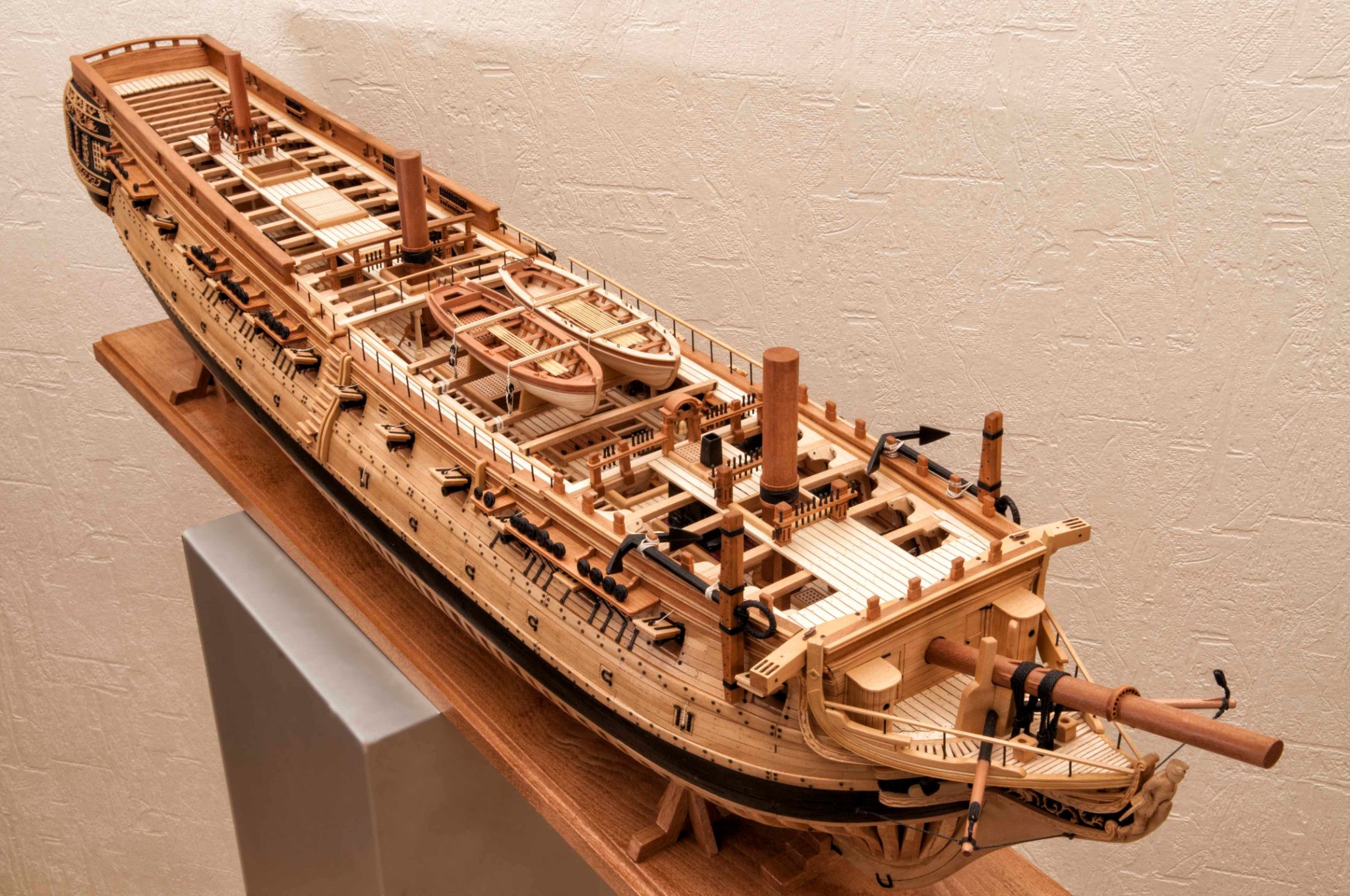
After nearly 4 years of searching, I have finally received information on the identity of the model shown below. It was found in an antique shop in upstate NY by a member of the Modelshipwrights of Western New York much as it appears today. Sadly the member has died and I purchased it from his estate as it is a superbly built scratch model of faithful reproduction. I just could not let it fall by the wayside in the estate liquidation.
With the help of members of the Hampton Roads and New Jersey modelers group it was found in the National Watercraft Collection publication by Howard Chapelle. Plans (lines and deck layout) reside in the Smithsonian archives and I have requested a copy to support my restoration.
The pictures attached are from my cell phone and as I cannot call myself an amateur photographer they will have to do until I invest in better equipment. The pictures do not do justice to the quality of this model so I add further description.
The model is about 27 inches at the waterline with a breath of approximately 6 inches. Given the information in the National Watercraft Collection second edition it would be 1:24 scale as that seems to be the size of the full scale vessel or 55 feet (WL). She is constructed of boxwood.It appears to be fully ribbed internally. I might add that the model has some years of age as the wood has mellowed to a rich creamy tan color. Everything about this model shouts it is the work of a master modeler. All planking, joinery, fittings, rigging and detail are flawlessly done. All deck fittings are scratch built from ferrous metal. All blocks and rigging treatment are of fine execution. The decking and planking is treated with simulated tree nails. The builder must have familiarized him or her self with construction details that can be found in Chapelle's e book, The Migrations of an American Boat Type, as they are so well reproduced in the model.
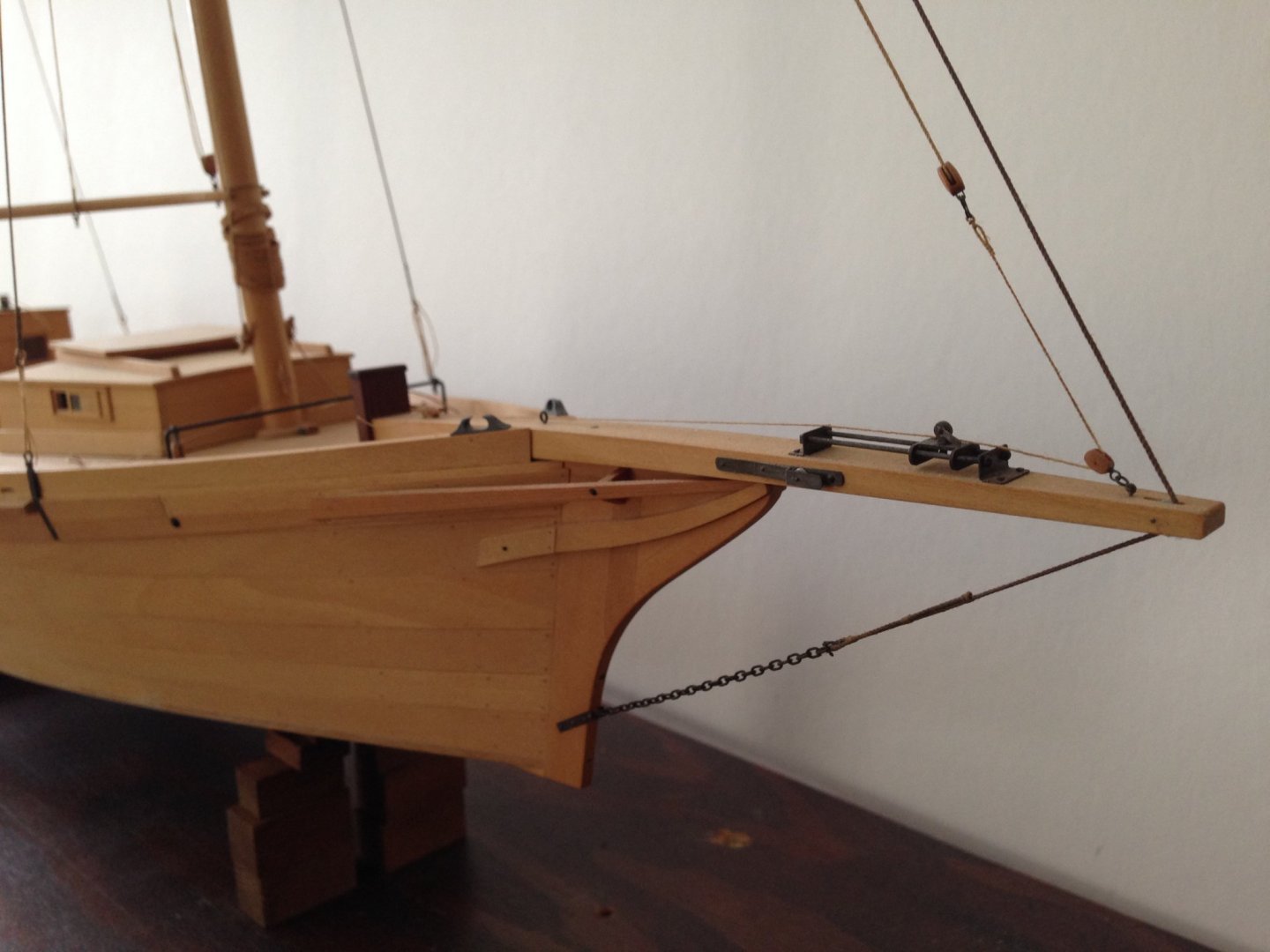
It needs some work, as in its travels some items are missing or in need of repair. These include some cabin and engine room hatches, the repair of the main well amid ship that has stared to come apart, rigging that needs repair or replacement and it sorely needs a new mounting and case.
I would like to document its restoration work for the sake of tje former modeler in hopes that someone out there may recognize her and possibly identify the person who built this fine model.
Work will begin when the Smithsonian plan shows up.
Joe


- jlefever, Siggi52, Ainars Apalais and 11 others
-
14
-
If you can get your hands on a copy of "The Classic Boat", The Time Life Library of Boating, there is a well done treatment of Jarvis Newman's restoration of Dictator (a Friendship). Pictures and detail to further add to this lovely model.
Joe
-
I just knew there were alternatives that my "b locked" thinking could not bring up. All good ideas everyone. i will do some experimenting. thank you.
Joe
- Keith Black, thibaultron and mtaylor
-
3
-
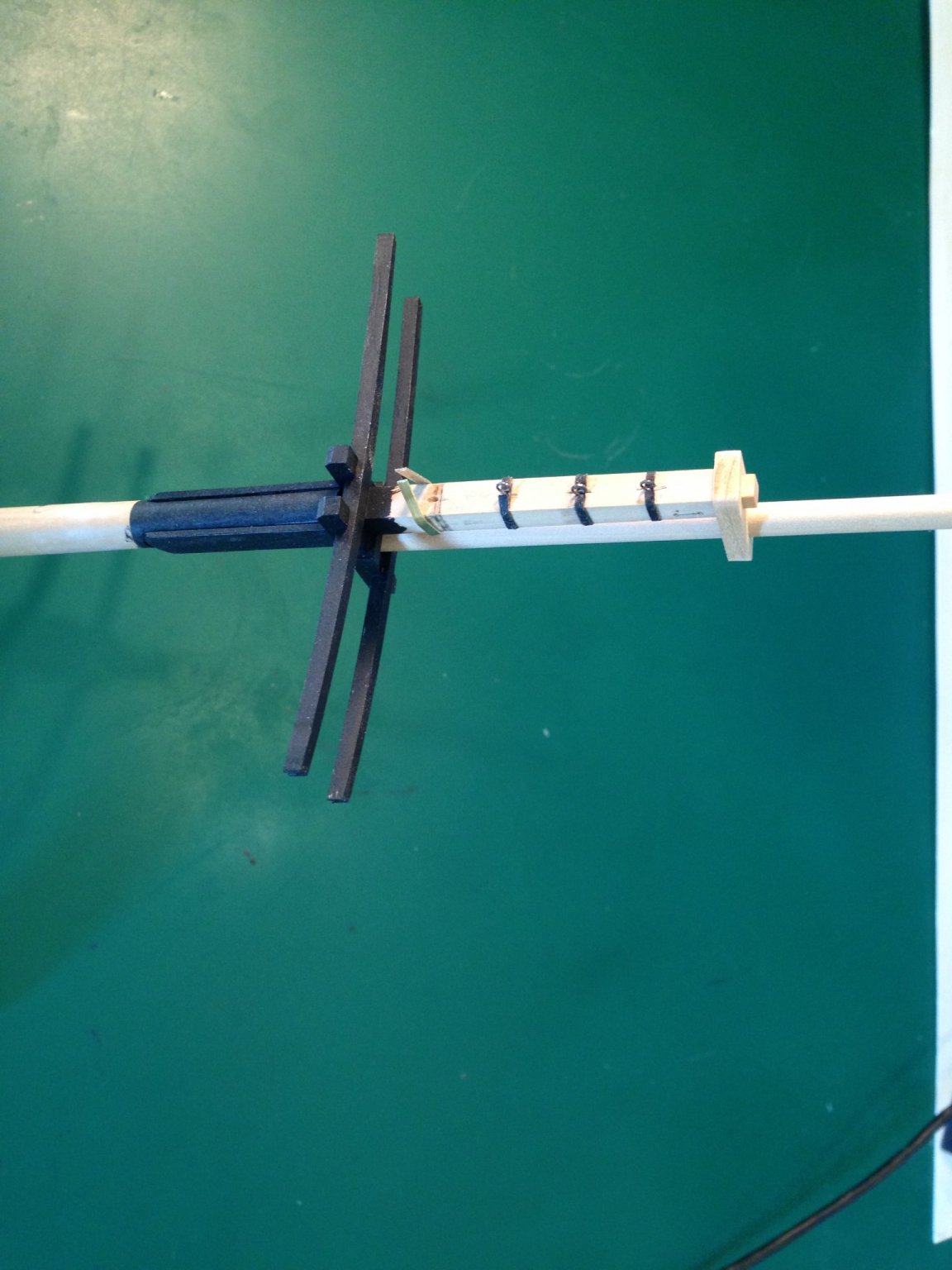
I am working on Cheerful and have been frustrated by my inability to fashion suitable mast bands out of brass. This has been agrivated by the fact that it is so hard to find thin stock of brass anymore as K & S has stopped making it. I did fashion some from 3/32 W X 1/64 T stock by milling it down to 1/16 wide. That is another story as the results weren't as satisfactory as I had expected.
In the picture attached I tried using tape of 1/16 width as shown in the top bands. It just so happened I had some printed circuit layout tape (that dates me doesn't it) and it adhered quite well. Yet it wasn't my prefered material. I even tried matte finish chart tape. I found it didn't stick well to the wood as it is intended for "glass like" surfaces.
I ultimately found a source for the brass I wanted to use and await its delivery. I might add I had to pay an outrageous price for this precious stock.
Now if you look at the lower band that I partially fashioned out of my modified brass one can see it is not completely formed because it has to be formed over the back of the mast and then formed again into a protuding tab that will support the final ring eye for rigging.
My question is "I know my problem isn't unique so what successful measures have folks used to do what I am tying to do"?
I would really appreciate help. Thanks.
Joe

- Keith Black, lmagna, mtaylor and 1 other
-
4
-
Your works are always so inspiring David! You set a high standard even for carving plugs for a model. Your productivity while maintaining the standard is also a wonderment.
Joe
- FriedClams, mtaylor, druxey and 2 others
-
5
-
Clogger I just can't bring myself to waste precious material by turning the kerf into saw dust. Having bought a boxwood billet recently (approximately 2 X 4 X 24) for $100 I find it a crime to cut that on conventional equipment even with a thin kerf saw blade. You would be better off cutting rough stock on a band saw and sending it through the Byrnes sander a few times as most of us do not have conventional wide belt thickness sanders in our shop.
Joe
-
Richard sometimes it is just as much fun to make a tool or jig! Nice work!
Having said that what I find that frustrates me is a device to hold my work piece that gets captured in the vise. I am constantly kludging something up to hold the part as the vise jaw depth is too deep or I need to reorient the piece or some such thing. It never seems to go away.
Joe
- RichardG, Canute, Roger Pellett and 2 others
-
5
-
Jim I just tuned into your build. I have been so preoccupied with other things I don't dwell on MSW as much as I would like.
Having said that the treatment you are giving your rendition is quite eye appealing and your work is impressive.
My Winchelsea sits at the bulkhead stage and right now witnessing your work I feel like the rabbit in Alice In Wonderland...."I'm late, I'm late"!!!!
Joe
-
-
-
Kiyoo I am not quite sure of the way you can make it exclusive to members of MSW. If I were you I would start with 2 people that may be able to steer you. Kurt Van Dahm (current chairman of The Nautical Research Guild) and Chuck Passaro of Syren Ship Model Company who has structured something similar to your needs in conjunction with the Guild.
One win/win just came to mind. If you were not interested in some monetary retun for yourself. What do you think of a way that would benefit MSW ( a contribution a member would make) that allows a download of your tutorial? Just an idea!
Joe
-
-
Would like to follow your progress. Keep it coming.
Joe
-
Kiyoo my experience with the results of the conversion (DXF to G code) taught me some lessons. For one, inside corners will always be rounded unlike laser processing. For outside corners the cutter has to go by the corner and return at the corner to have it come out square. As with laser machining there is always the feeds and speeds issue but the hardest lesson was that laser instructions seem to be much more forgiving in terms of path travel (we found arcs that were not continuous in the laser file that would not work in the CNC mode). Discontinuities in lines, arcs have to be "smoothed", nodes must be precise and so on. All in all i got my parts (for bulkheads and strongback) and they came out well. I believe you are absolutely correct that laser machining is the way to go. It would be the premier way if one could find a solution to char and the "slope" of the cut.
Joe
-
Klyoo I have explored this arena (bringing today's technology to this pursuit, I worked with a colleague to convert laser DXF files to CNC G code, it was a real eye opener for me) but I pale in your light and work! Just outstanding. I await your completed treatment of the process but follow your good works.
Jooe
-
Hugo I assume you have used the planking tutorials on this web site, namely within the forum you have posted. So one has to ask have you created/added a simulated rabbett on the bulkhead strongback (center element that runs along the keel). Have you carved out the stern area of this element (deadwood in a real keel) so that your planks will lay down flush with a later added stren post? At times some slight tapering of these planks is acceptable to have them lay correctly in the stern area. Does this help?
Joe


Lightning Sailboat by Andrew J. - Small - Scale 1:12 - Sparkman & Stevens Plans
in - Build logs for subjects built 1901 - Present Day
Posted
Dome that too but not in a Lightning! Ok, ok i will throttle it back and let you get on with the model.
Joe