


Thistle17
-
Posts
1,042 -
Joined
-
Last visited
Content Type
Profiles
Forums
Gallery
Events
Posts posted by Thistle17
-
-
Shown below is a typical gun tub for the model. It is the best close up image we can find. Now I think this is mounted on a MK II but as best we can tell from the drawings we have it appears identical. Combined with our drawing file and this photo we are going to fabricate the gun tub as follows. We have produced 2 very accurately diameter discs out of 3/4' MDF that will form the top and bottom of a form. The center alignment hole has been accurately placed and will help in alignment when we bolt the 2 forms together. Now the overall height of the gun tub to scale is 3 1/8" inches tall. To fashion the gun tub we will sandwich in between the top and bottom discs separators (of slightly smaller diameter than the two discs of 7" diameter) to achieve the 3 1/8" height. The assembly will be bolted together. The two disc edges will be refined so as to limit the possibility of glue adhesion. One thirty second (1/32") basswood will be machined into staves and mounted to the form. The staves will be edge glued. Clamping bands can be used to achieve conformal shaping of the flat stock onto the form. The overall outside diameter is 7 1/8" Hence a second layer of 1/32" will be repeated.
The gun tub rings can be fabricated in a number of ways but the preferred method is to have them laser etched from either suitable thickness plywood or laser board.
We think this will work and will be working this over the next week.
In looking at the gunner in the photo one cannot help but wonder about his hearing problems as a result of his placement. Did these guys sacrifice themselves or what???
Joe
-
Let me suggest we continue a dialog on this.
Firstly there is a note somewhere either in MSW on fence alignment or elsewhere and I just have forgotten. In that note it suggests one tighten the front lock down and then apply slight pressure to the rear lock down to provide "out board" clearance for the stock as it is pushed past the cutting edge of the blade. This implies there is some bias to the fence parallelism to the blade and not the slot????
Secondly, I have to ask in regard to the mitre perpendicularity, when you say you have a 1 degree error how and what are you measuring it. With my best square I have measured the mitre perpendicularity to the blade and with in my capability I do not see any deviation. I have noticed it can be "easy" to have the test piece move while cutting as the finer tooth blades do offer some side thrust to the work piece. I would also check that the blade is mounted correctly/cleanly on the arbor.
Joe
- Ryland Craze and mtaylor
-
 2
2
-
Yes Mark thanks it slipped my mind. I will repeat for all these drawings are more or less renditions of the major components and as such have no measurements, cross sections etc. On the other hand the Navy drawings are quite detailed including all dimensions and detailed cross sections that in some cases even define the bolt hole patterns and the like. What has confounded us a bit is to decide what vintage of the model we would undertake. As we have numerous photos from on line ( that are in the field or state side) and other sources, including Patriots Point excellent photos, it has almost become a "TMI"(too much info) situation. So we have leaned more to the "as built" configuration.
Now the build posture has been from the outset, to construct a waterline model that will be placed in a diorama like setting at the museum where we meet. The setting will be a dockside setting with all the scale artifacts that the museum has collected. With that framing the model will be as authentic as we can make it "topside" but will not incorporate "undercarriage" detail that cannot be seen by the public.
I have related this before I just thought for new viewers it would be beneficial to repeat once again.
Joe
- druxey, Canute, Roger Pellett and 1 other
-
4
-
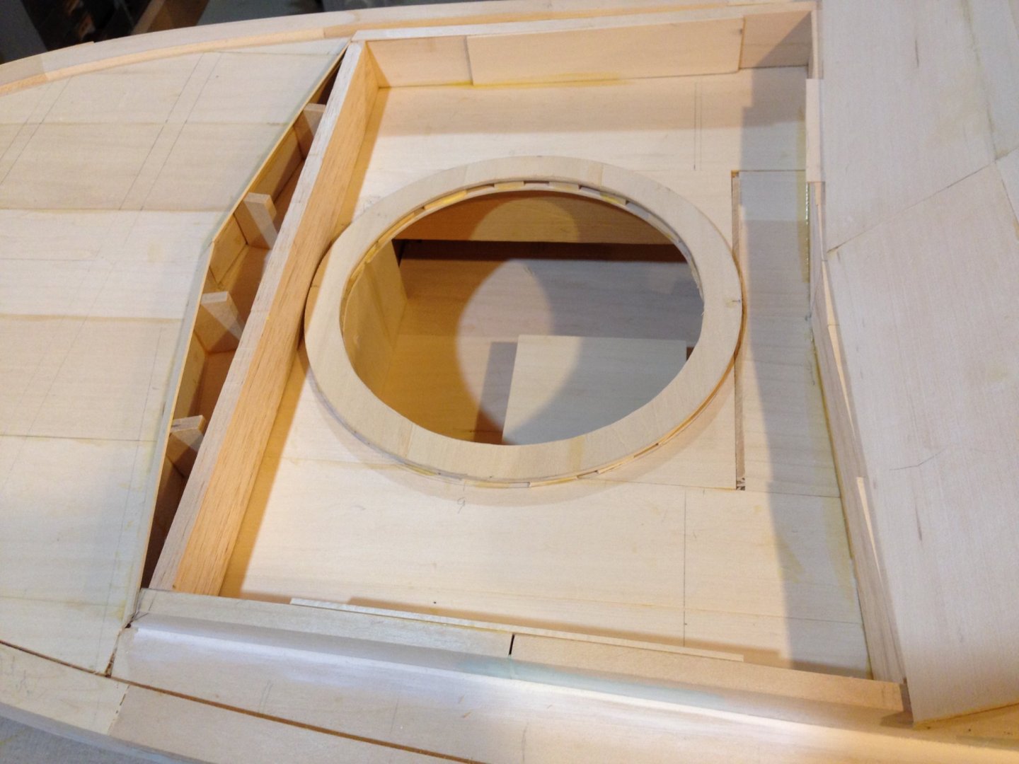
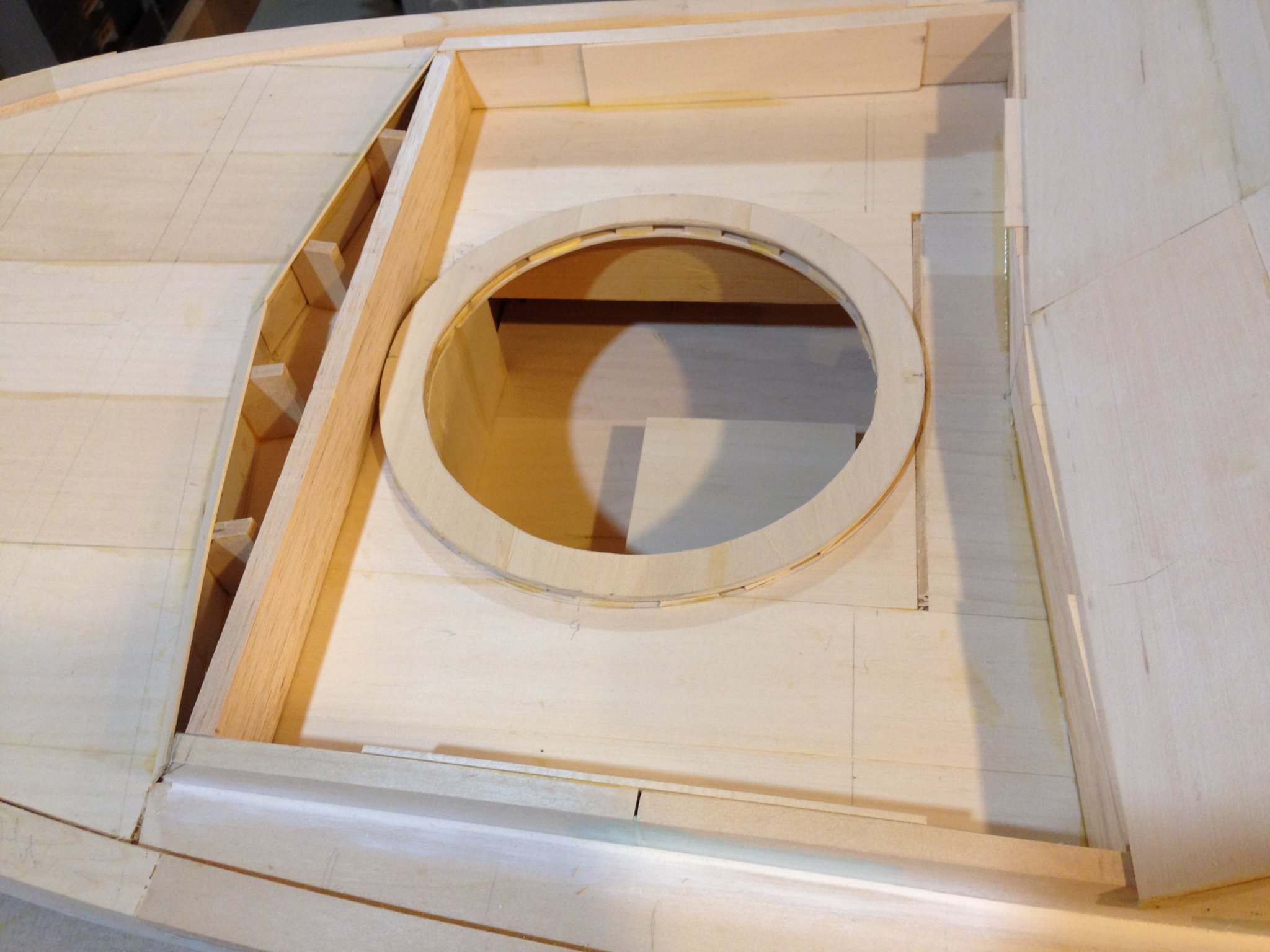
Just saw your post and would be indebted to you in regard to the color i.e. what do you signify by "OD". Secondly Can you say more about the forward gun mount comment you made. We are using two sets of MKI drawings. One is from what I call sketches from Maryland Silver that is now defunct and we did acquire drawings from the Navy that are termed "as built". The current state in the picture above is that is the lower support ring mounted to the false deck and we will be building the tub upwards from there to a height much above the skinned over raised deck area that surrounds the gun tub. As a matter of fact we are converging on this Tuesday to define the correct height of the tub. If you have MKI pictures etc. that may help us it would be appreciated. We will be adding twin 50s in the tub.
Having said that we are aware there were a good deal of field "upgrades" to these boats and while we are mindful of that we have had to define a point in time that these vessels were more or less delivered to the Navy. We certainly would appreciate your continued feedback.
Joe
-
Here we are a month later moving a bit farther forward on the build. Our "chief engineer", Jim is headed for Florida in a week for two months, so on board now is Bill. Bill has a long history of model building and you may know that he has a number of models donated to the Navy and museums. He is a period ship modeler concentrating mostly on Civil War era vessels. Welcome aboard Bill!
Today we managed to permanently install the forward gun tub support ring and continue work on the helm area interior compartments. In the ensuing weeks we will concentrate on completion of the gun tub and forward deck skin. The helm area will also be finished and readied for the helm station and radios etc.. The gun tub support collar will rise up from the support ring and will receive an inner collar (with a circular flange that is part of the rotating system that supports the twin 50 caliber machine guns. At this time we do not plan full simulation of the tub rotational mechanism since most or all is hidden. We will add realism through simulation of fasteners and the like.
The gun tub is a bit involved and it seems at the moment more appropriately built at the model rather than farming it out as originally planned.
Joe

-
I am stalled on working this endeavor as I am remodeling a first floor work area in our house for both my wife's art works and my model building. In doing so I had to move some 1970 ish model kits from a well known US manufacturer. It was striking to open the box of Rattlesnake and examine the dormant kit. I mused to myself, in today's light, that the kit should go to the "auction block" or elsewhere.
Indeed the industry has come a long way in nearly 50 years especially so in the last 10 or so. But Chuck, I think I speak for all modelers when I say you have advanced this wonderful "passion" to a level that may not be achievable in a full production environment. And it is hard to see how it can be surpassed! You are truly gifted and the fact that you share your gifts is remarkable.
Joe
- gjdale, Captain Poison, Beckmann and 9 others
-
12
-
Given good weather and your ability to attend our March meeting it would be delightful to see your project. Hope it works out. The choice of wood is going to make such a warm looking model Rusty.
Joe
-
I have been ordering ahead even though I have yet to launch head first into this project as I am setting up an artist work area for my wife. We share a common work room and my wife has been patiently waiting for her area for far too long.
In any event I just received the full resin set of parts Syren offers. They are astounding in replication and detail. Although his supplier continues to work at improvements these are the best I have seen from any supplier to date.
Joe
-
One never knows when you take on a project for someone else how it will be received and what will come from the interplay along the way with the client. I must say in this case the outcome has been beyond any thing I would have imagined. My wife and I have become quite friendly with the client. I doubt that is the rule in such undertakings. It has been delightful knowing the person who is one of those rare people that each time you meet it is a joy. How good is that! Just had to say it.
Joe
-
-
In furniture making a 1/32" is easily handled without lament. In model ship building it can be dreadful. I have learned the hard way that tolerance build up, even with careful machining on very good model machines can creep in so easily that I have had to adjust my mentality from one project to the other. By golly you are human after all!!!!!
Joe
-
Bob this pursuit has its own way of making oneself a harsh critic of their work. This forum offers us all superb references for "how to and perfection". It is both a blessing and a curse. In building Cheerful (which is still in process) I learned so much and have improved immensely. You are way ahead of me (maybe that is not a good reference point)!
Joe
- FrankWouts, Elijah and Martin W
-
3
-
My long departed German friend taught me to be neat and orderly and clean up before one leaves the shop. I have high admiration for him and his works. He apprenticed in Germany to a wood carver and that rigor was among his first lessons. Nice discipline!
Joe
-
Superb execution Mike. You are another hard act to follow. And thanks for the tip on the sanding forms and paper. I am always fashioning up homemade ones that are barely adequate.
Joe
- Martin W, FrankWouts and Stuntflyer
-
3
-
Nice to tune in and see your great work and progress. How you and the others manage to stay the course is a mystery to me. Life for me has many interruptions. Winne sits on the shelf while I add den cabinetry for my wife's art works. For now I will have to content myself with yours and the others works. Happy New Year!
Joe
-
Inspirational! Obtainable, now that might be another story!
Joe
- FrankWouts and Chuck
-
2
-
Remarkable drive Jon! I have been in this house 11 years now and I am still trying to finish my wood working shop and model building "shop". The former is in the basement and the latter is on the first floor. I just finished the second installment of cabinetry for my wife's art work area. This all meant that I get about an hour a day to model. And yes finding the tool or glue bottle is a universal problem. I have Channing's Friendship plans and hope some day to build a scratch version. Love those Maine work boats. So much to do and so little time!
Joe
-
I too have this saw Jaagar. Mine is referenced as a veneer cutting saw and also does a good job of cutting for modeling but does not quite have the "clean cut" of the former one I suggested. You do point out the one thing I like about veneer saws and that is it is easier to start the cut with the one you suggest. I have found that with the Japanese version if I scribe the cut line first the pull sawing is much easier.
Joe
-
Bob your work inspires us all. Nice clean execution and progress. My work has stalled as i have wood shop projects "on the ways" that desperately need to be launched. I need to adopt your focus/mentality about this project.
Joe
- Matt D, FrankWouts and Elijah
-
3
-
-
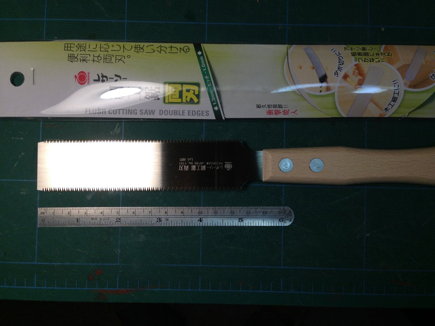
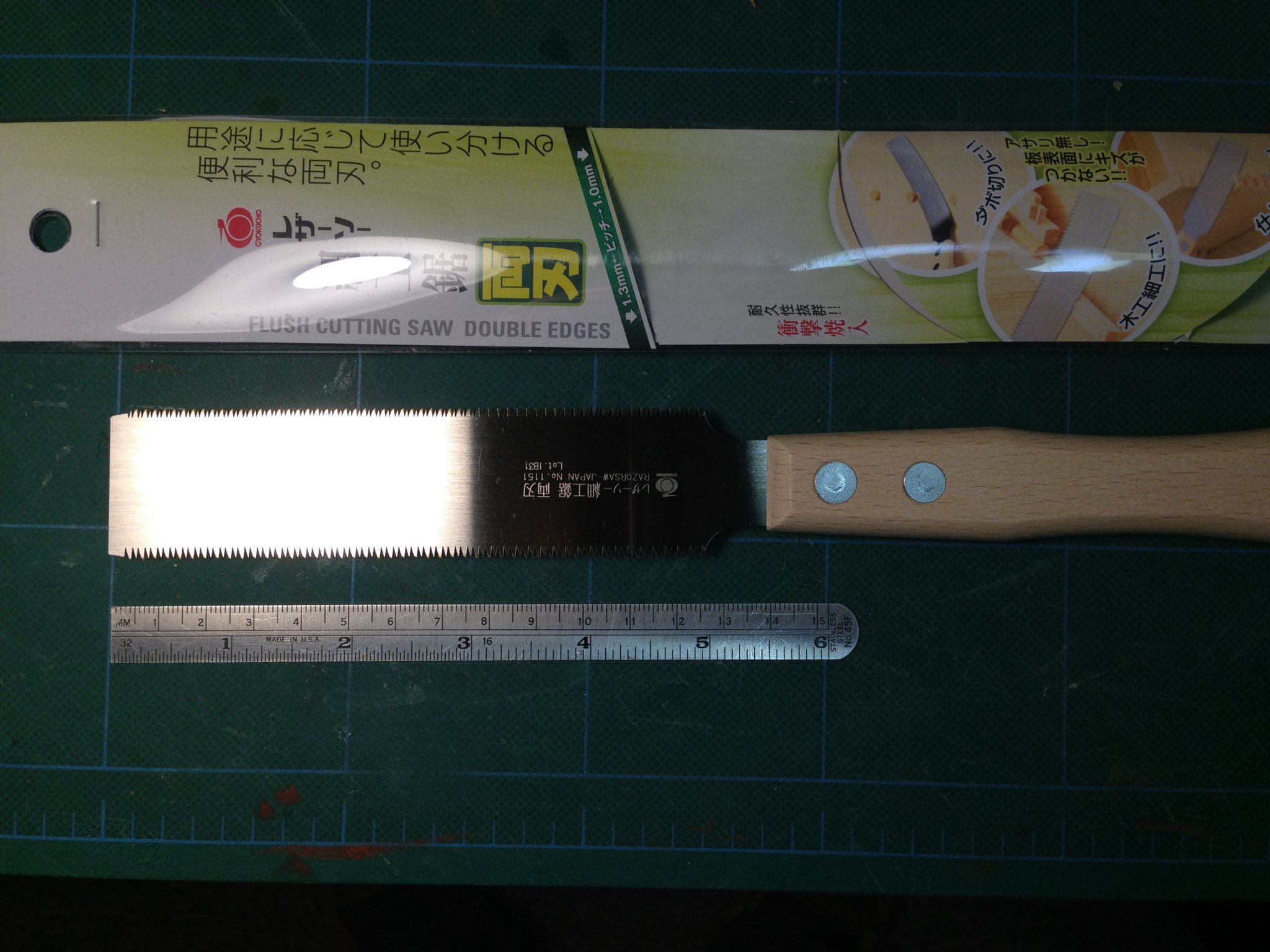
I have found several tools that have migrated from my wood working chest to my modeling chest. The latest is this Japanese flush cutting hand saw that has been a real surprise to me in modeling. I have had other style flush cutting saws but none have proved to be as good as this one. It has a blade thickness of 0.0120 inches or 0.30 mm. It has 2 blade pitches, the finest is about 0.725 inches. There is zero tooth offset and it is incredibly sharp. As with most Japanese saws it is a pull cut. I purchased it from Lee Valley for a few dollars .
Joe
-
-
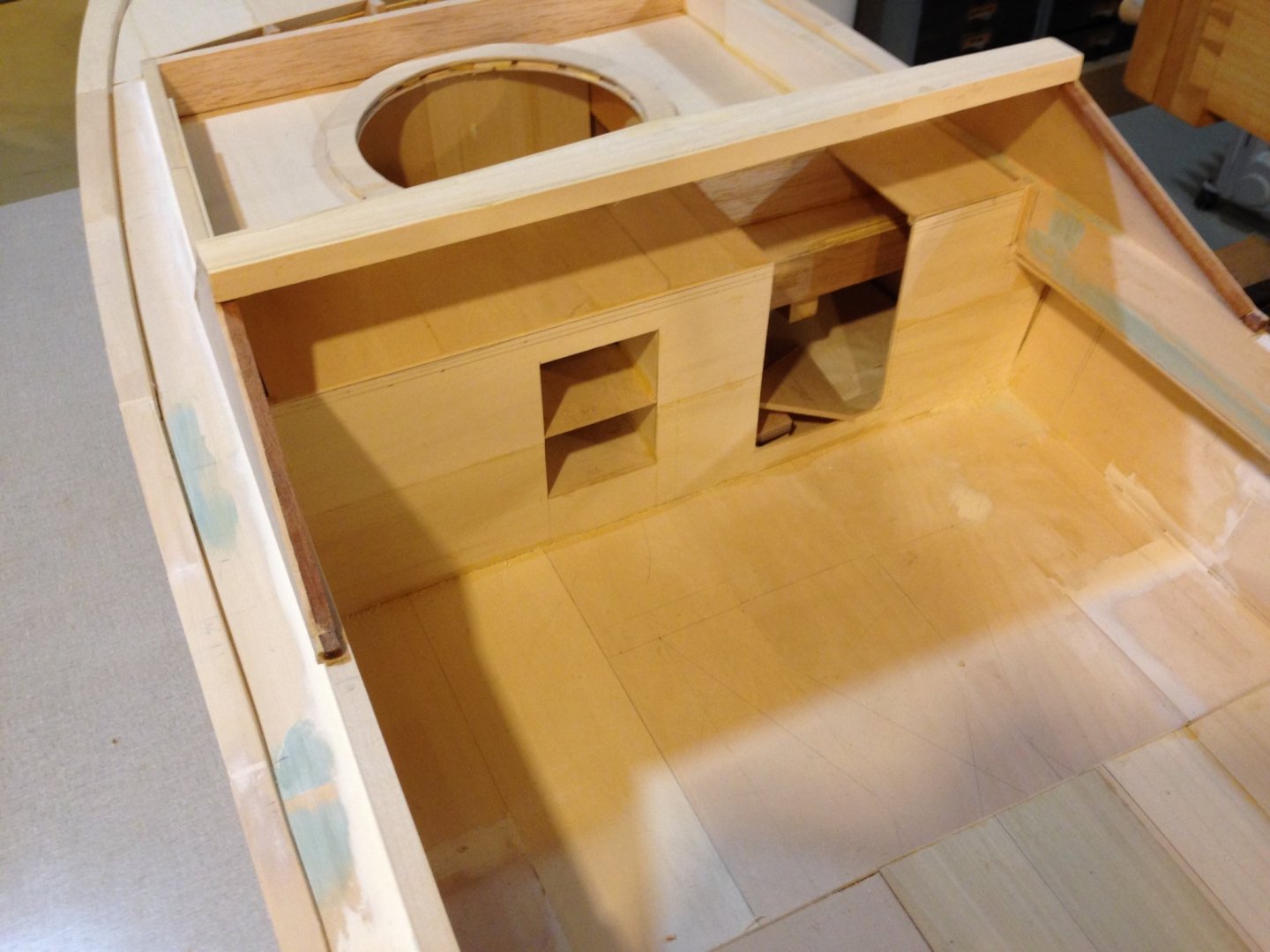
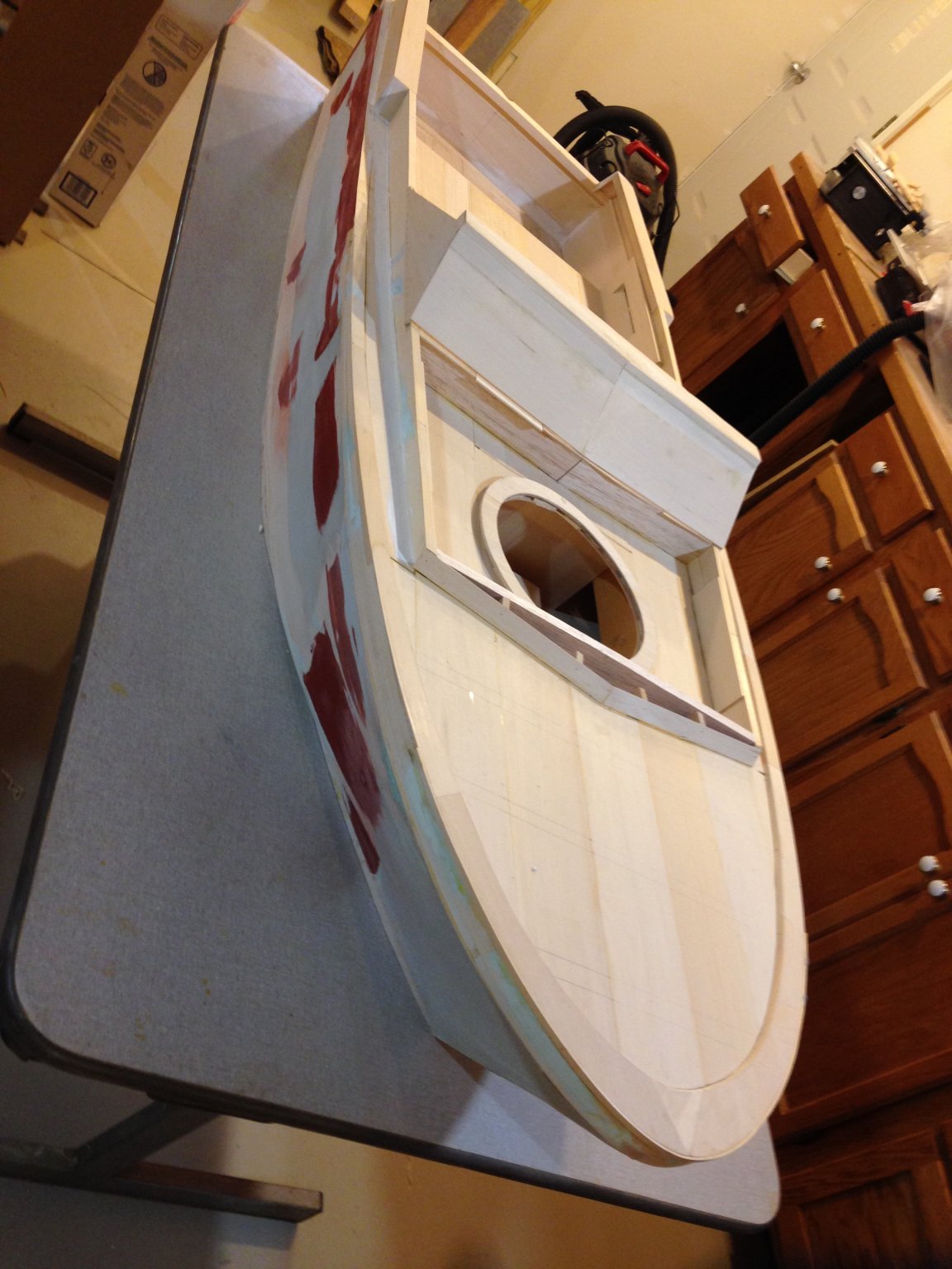
Today we dry fitted the helmsman cowling and the forward decking. Forward of the cowling is the beginnings of the gun tub. The ring is the base support for the gun tub. Structure for the deck above that will soon be added and that entire area will be decked over. While fitting the cowling for the helm we also determined the inner support/finish members that will be needed to complete the operational area of the helm. The control station (not shown) and the cowling were built off line by another member, Matt, following drawings supplied by our "building supervisor". Given the variability that could creep in base and off line development, assemblies have fit quite well.
Joe
![IMG_1414[1].JPG](https://modelshipworld.com/uploads/monthly_2019_12/528505319_IMG_14141.thumb.JPG.4a26f33d5bf88a07b31b54f85b05ac9b.JPG)
![IMG_1416[1].JPG](https://modelshipworld.com/uploads/monthly_2019_12/1603409199_IMG_14161.thumb.JPG.65a825e8d5bb90ac4ca64d1b2c7f9fa7.JPG)
-
Hank you could build a full sized craft in there! I toyed with that idea in a shed I recently built. I was talked out of it by wiser people than myself and went back to building models. I would assume you have thought of this but if you have not heed the following. One of our group members is/was using his shed for model building but found the humidity gave him all sorts of problems. So much so that he had to restart one project that ended up with a warped keel. He lives in upstate New York on one of the finger lakes. Hope you are putting this space under AC.
Joe

![IMG_1414[1].JPG](https://modelshipworld.com/uploads/monthly_2019_12/1215310344_IMG_14141.JPG.86123fb34de74e49ee3582cfdb4223c3.JPG)
![IMG_1416[1].JPG](https://modelshipworld.com/uploads/monthly_2019_12/1164608058_IMG_14161.JPG.944d889062613001d3c762e1b51f6f3d.JPG)
HMS Winchelsea 1764 by Rustyj - FINISHED - 1:48
in Member Build logs for the HMS Winchelsea
Posted
Fairing the inner bulkheads isn't fun no matter how one approaches it. I didn't find anything to like about it on Cheerful save I could say it was done. I am not looking forward to this aspect on this model even though you make the outcome worthy of the pursuit. The cap looks superb. I am assuming there is a outboard detail to be added in the future to the cap??? She is a beauty Rusty!!!!
Joe