ccoyle
-
Posts
10,601 -
Joined
-
Last visited
Content Type
Profiles
Forums
Gallery
Events
Everything posted by ccoyle
-
 Stabilizer fillets and elevators added. A curious factoid: the diagrams show a trim tab on the rudder which the kit parts lacked. I did some web searching to see which was correct -- turns out the A6M2 had a rudder trim tab, but the A6M5 did not.
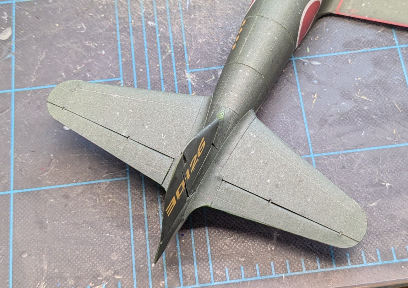
- 112 replies
-
- 14
-

-
Nice work, Andy!
-
Welcome back! In some respects, the first planking is the hardest. You have gotten the second layer off to a good start!
- 139 replies
-
- 1
-
-
- Lady Nelson
- Amati
- (and 2 more)
-
Intriguing!
-
Condolences on the loss of your pet. It's not easy to say goodbye.
-
Welcome aboard!
-
Check out these offerings from Woody Joe: https://www.zootoyz.jp/contents/en-us/d2045761086_Japanese-Sailing-Ship-model.html
-
Good luck on your project! I built Chris' first iteration of Sherbourne, which he designed for Caldercraft many moons ago. The new design is much more beginner-friendly.
- 9 replies
-
- 3
-
-
- Vanguard Models
- Sherbourne
- (and 1 more)
-
Sometimes these older 'beginner' kits can be quite a challenge! Good luck on your project, and don't be afraid to ask for help.
- 6 replies
-
- 1
-
-
- St Helena
- Constructo
- (and 1 more)
-
Hull Finishing Examples
ccoyle replied to Burgundy's topic in Painting, finishing and weathering products and techniques
I hope you have a copy in hand? I checked at ME this morning, and their links to the practicum chapters were broken. -
Hull Finishing Examples
ccoyle replied to Burgundy's topic in Painting, finishing and weathering products and techniques
@Chuck has achieved some excellent finishes with basswood, and he has described his methods in several practicums. He'd be able to direct you to them more readily than I can. -
Hi, @Bontie. I have moved your query to the kit discussions area. To get an answer, you will probably need to be more specific about the "references" you refer to. Hope you get help soon!
- 1 reply
-
- 1
-
-
Check out this nearly-completed build log:
-
Witam! I am a fellow fan of card modeling, though my work does not approach the level of the Polish masters. Glad to have you aboard!
-
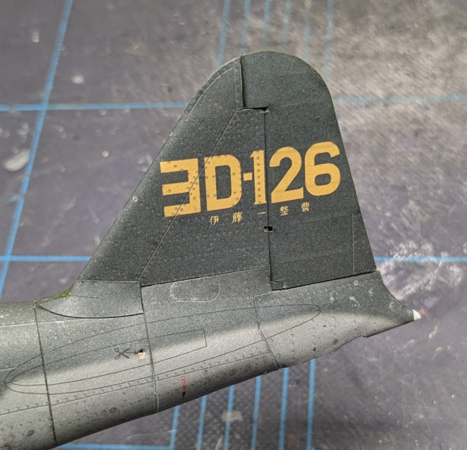
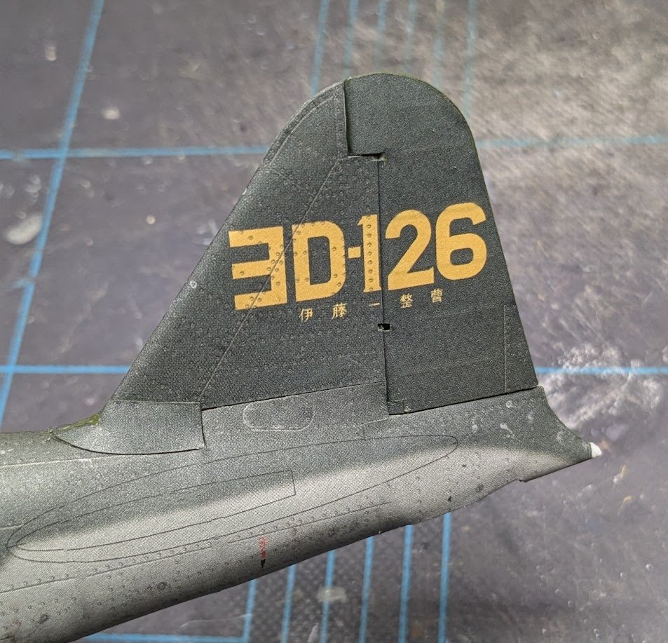
Completed the vertical stabilizer and rudder. Here we have the rudder framing and cladding. I added a joiner strip from scrap card. And here's the finished assembly. And, just for fun, here's the same shot of the rudder after being massaged with "magic erase". 🤫

- 112 replies
-
- 15
-
-
Welcome aboard, Gershon! I'm sure some members will chime in shortly with suggestions for rigging references. I have tagged your project as a first build, which should draw some extra attention to it. Good luck with your project!
- 4 replies
-
- 1
-
-
- Enterprise
- Constructo
- (and 1 more)
-
A noble and kind gesture! The model turned out well -- I'm sure she'll like it.
- 56 replies
-
- 2
-
-

-
- Lindberg
- sternwheeler
- (and 1 more)
-
The AI problem isn't limited to just Google. The internet is simply awash in AI-generated crappola grande. And I'm sure we all have friends who seem to be completely incapable of detecting it and insist on flooding their social media pages with it. As always seems to happen, dimwits and ne'er-do-wells have taken a potentially useful tool and largely ruined it. 😢
- 732 replies
-
- 7
-
-
-
- Lula
- sternwheeler
- (and 1 more)
-
"Magic eraser" -- I'm tellin' ya, that's the secret!
-
I love all that nice, cool overcast in your photos! Makes me miss the Pacific Northwest, especially between now and October here in the Deep South! 🥵
- 72 replies
-
- 2
-
-
- Miss Adventure
- Model Shipways
- (and 2 more)