KeithAug
-
Posts
3,985 -
Joined
-
Last visited
Content Type
Profiles
Forums
Gallery
Events
Everything posted by KeithAug
-
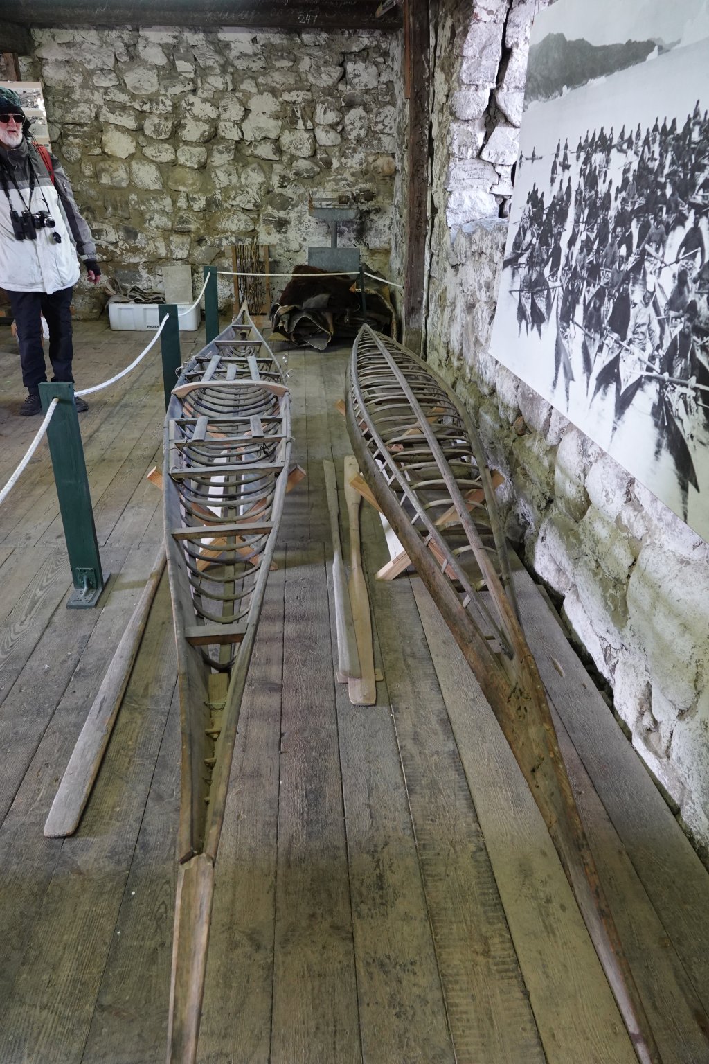
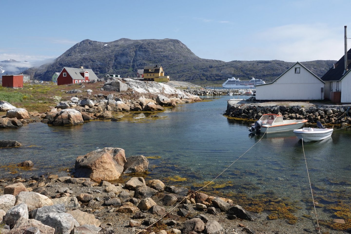
 Hello John - yes - we were in Greenland when the offer to buy was made. It didn't seem to prompt any celebrations. Funnily I did think of you while in town of Nanortalik. The town had a museum with a good display of traditional Kayaks. I thought you might like to extend your canoe building skills. More pictures available if you are interested. Because Greenland didn't have trees the kayaks were made from driftwood. Eberhard - I have to agree that the Greenland people were lovely, very friendly, gentle and welcoming. As tourism develops maybe things will change but for the moment it remains an idilc destination for those who want to avoid tourist traps. Nanortalik:-
-
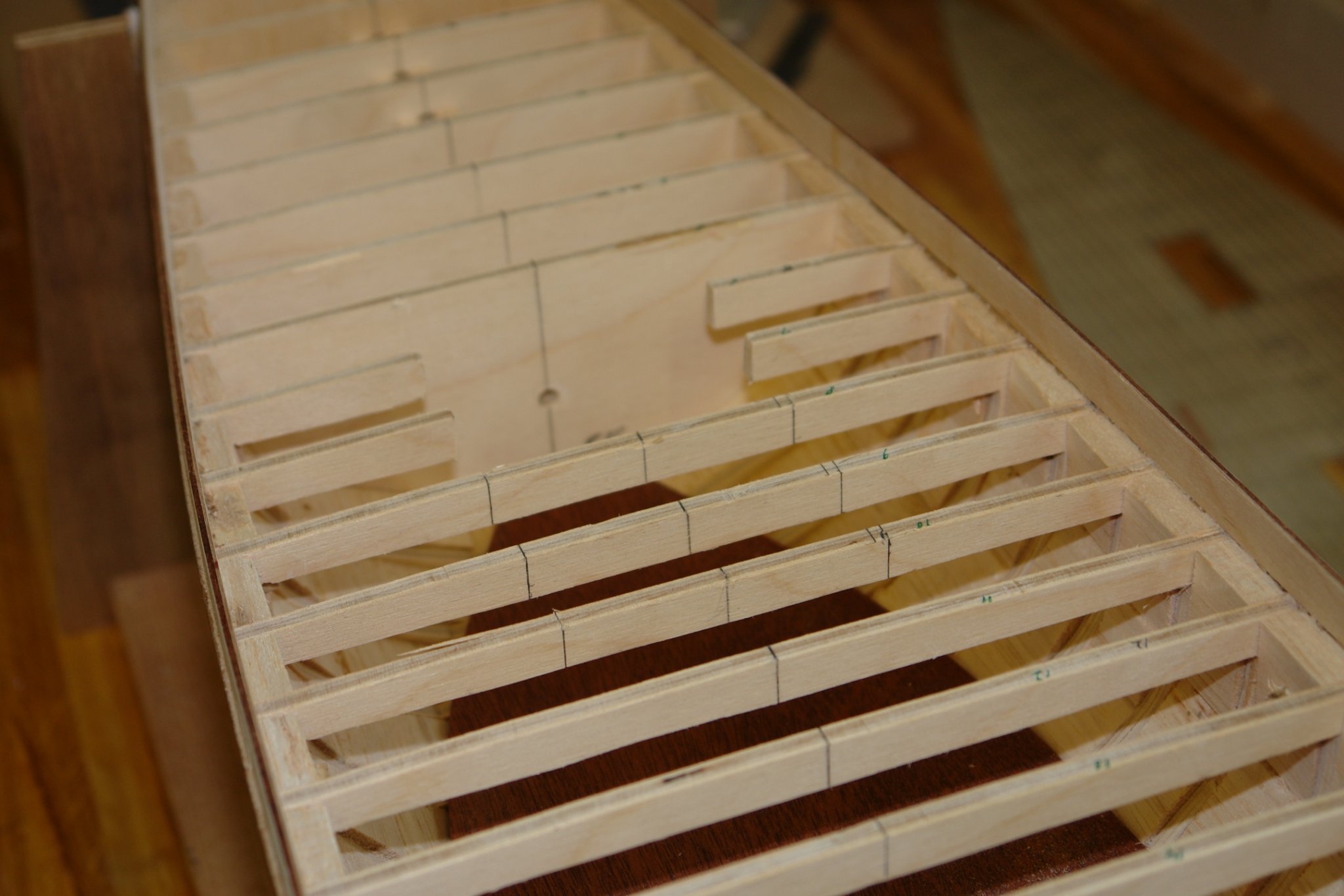
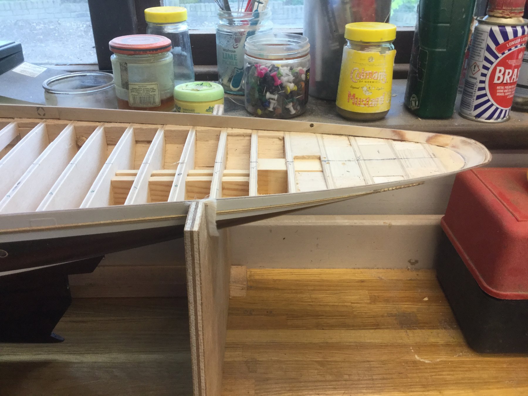
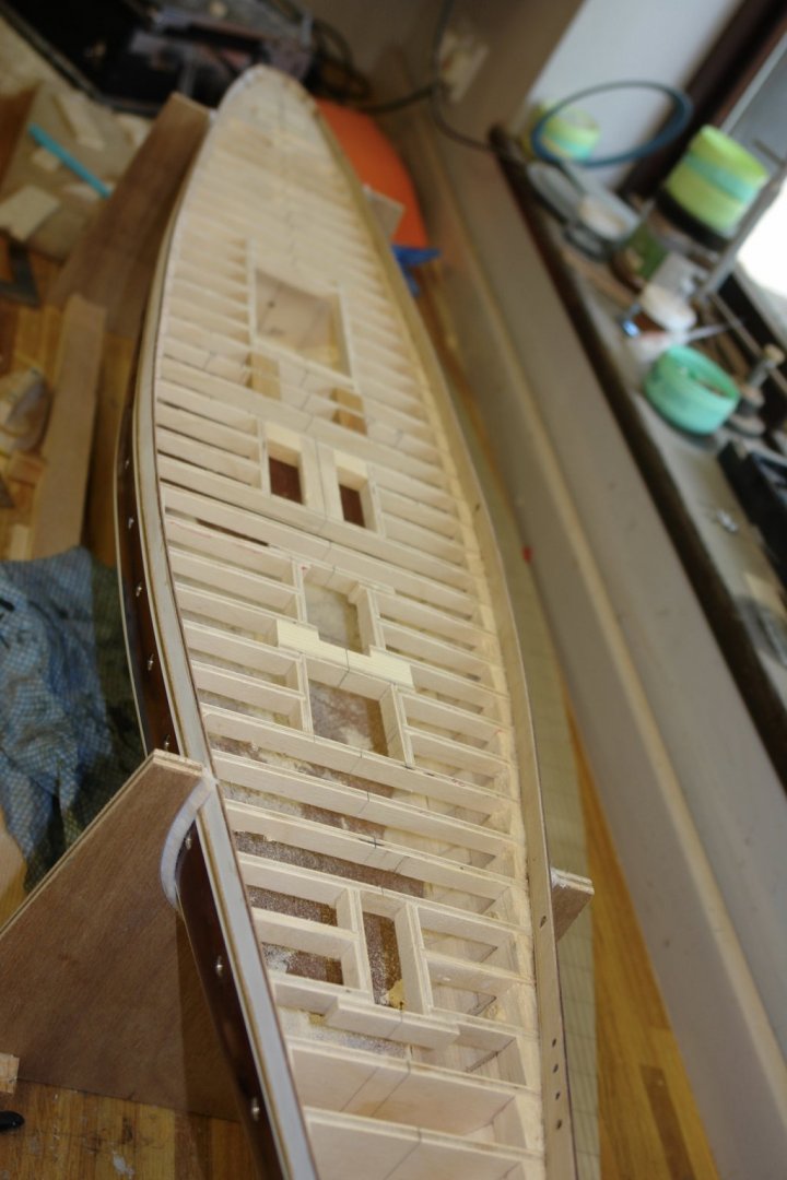
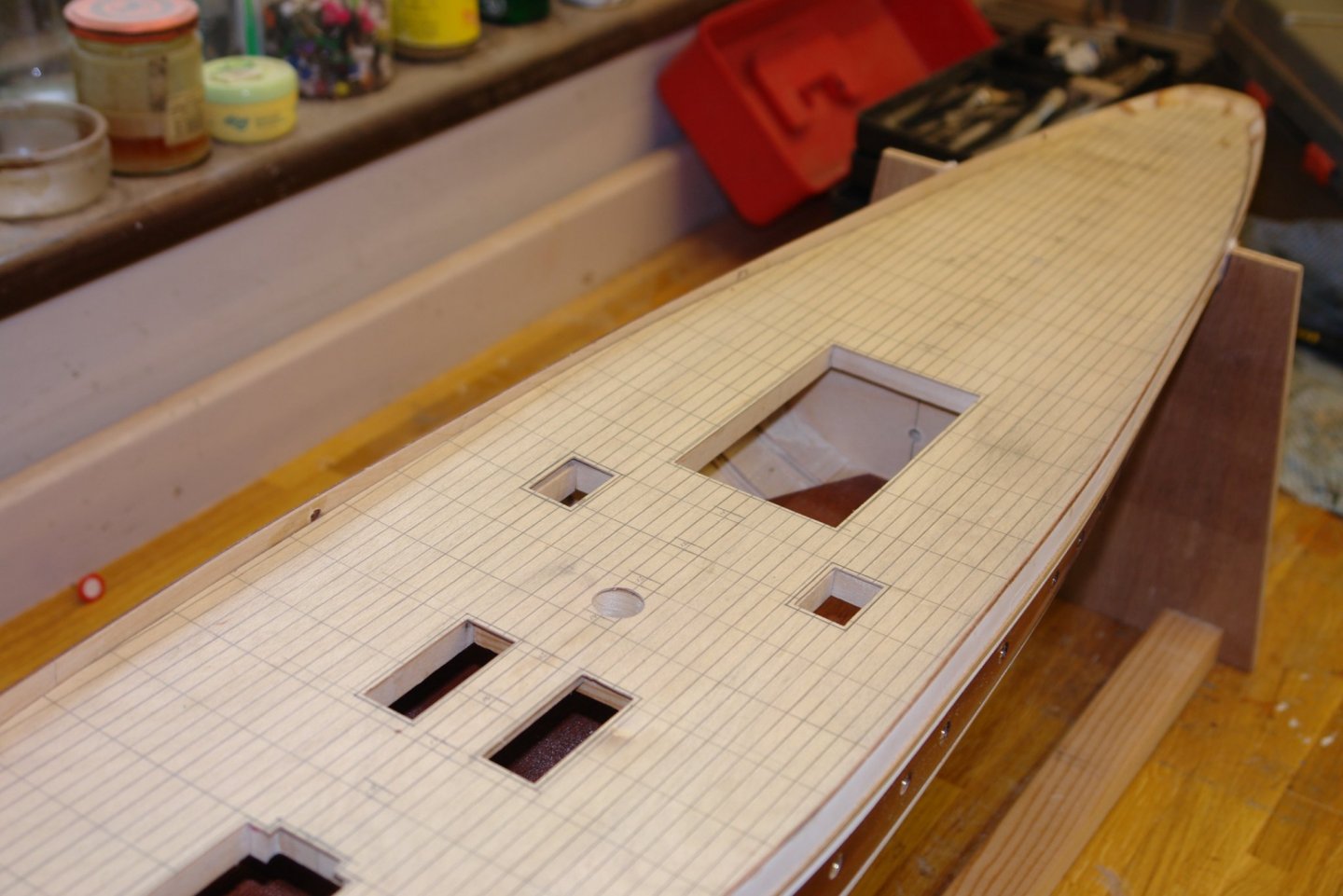
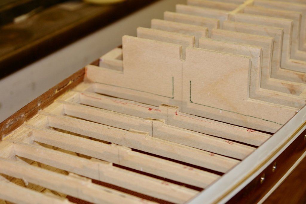
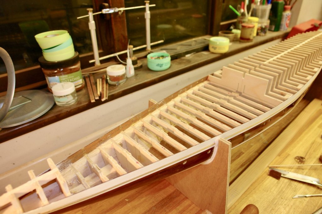
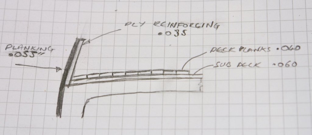
Hi Bedford. Interestingly although the cruise was from Tilbury about 10% of the guests (80 people) had flown in from Australia to join. I have just senp a couple of days getting restarted on Germania. You may recall that I had previously marked out the sub deck in preparation for planking. I had also marked out the positions of the cut outs for the various deck houses and these were removed with a craft knife. Once the holes were cut out I transferred their positions to the deck beams in preparation for removing them. The beams were subsequently cut away with a razor saw. Additional beams were then added to provide all round support for the deck penetrations. The sub deck was then placed back in position to check that alignment. I will start on the deck planking next.

-
It was June when I last posted and haven't built much since. I now have the laptop back from the repair shop - took 8 weeks - not impressed. Fortunately it overlapped with a holiday cruise to Iceland, Greenland, and the Shetland islands. Most of the time was in Greenland which I have to say is absolutely spectacular, lots of mountains and icebergs and very few people. Greenland is half the size of Australia and has a population of 56,000. Thank you all for your visits and comments during my absence. I'll do an update on progress over the next few days. In the mean time I will enjoy catching up on the good work you have all been doing.


-
Nice start Patrick. A super yacht that actually looks like a boat - what is the world coming to.
-
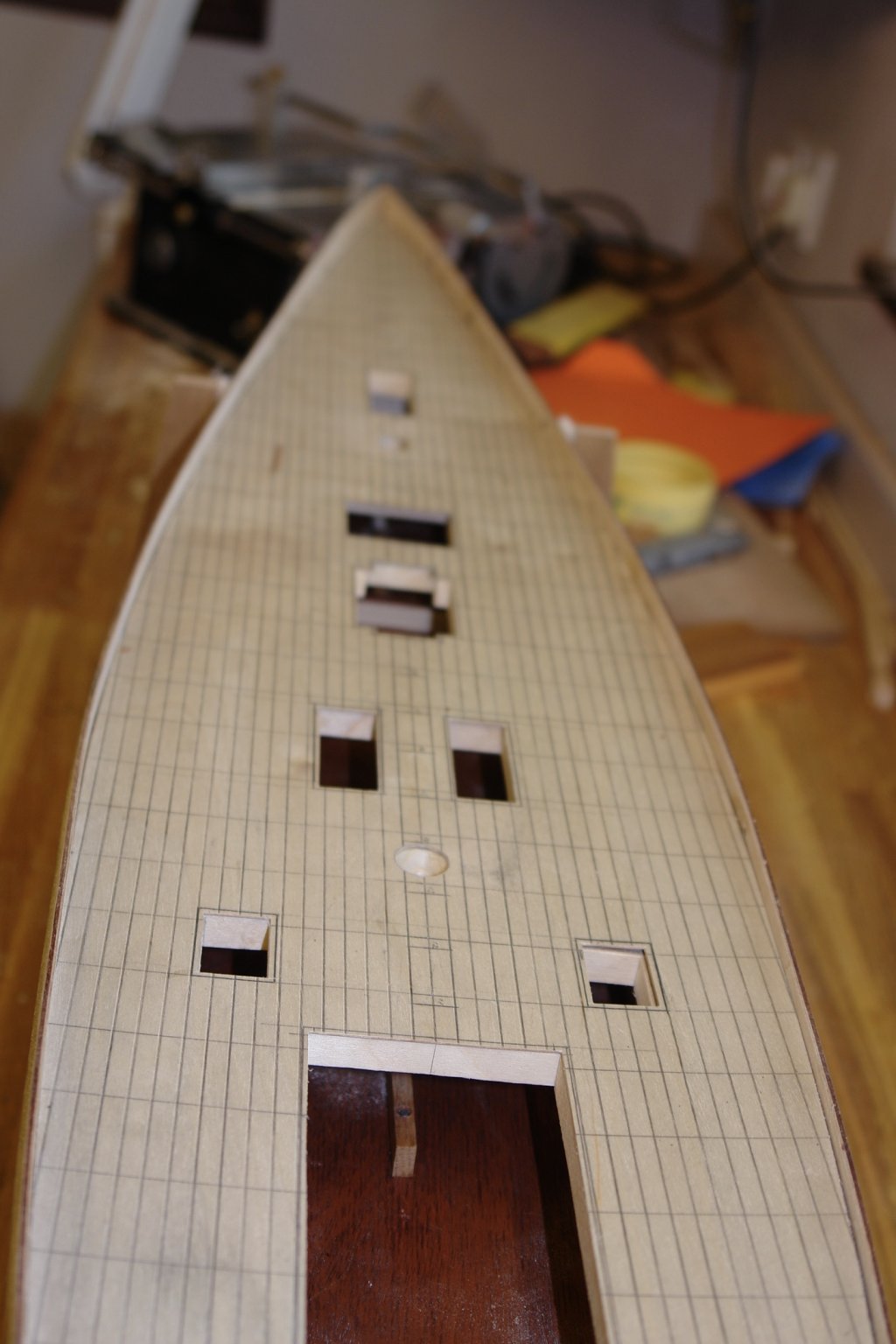
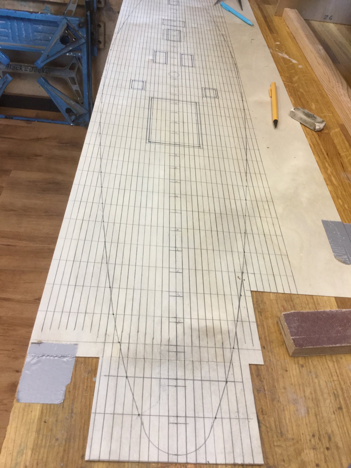
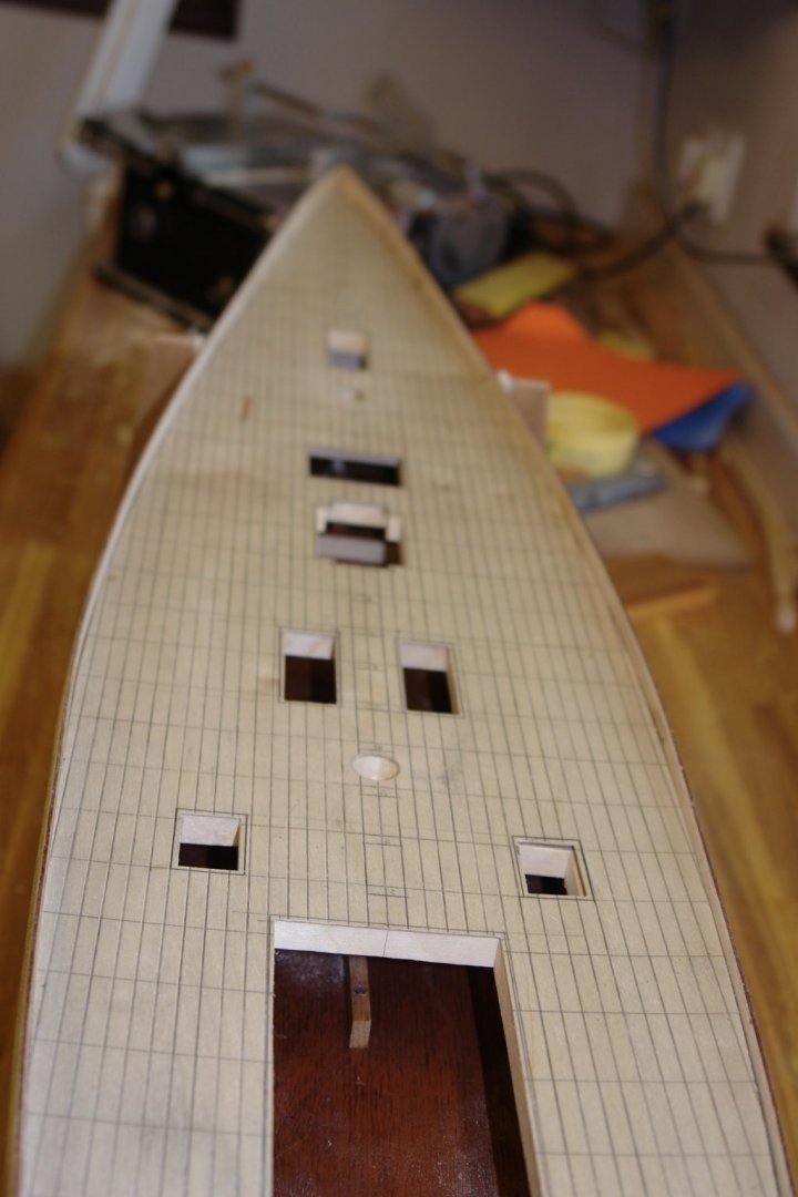
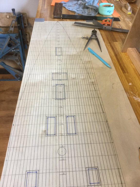
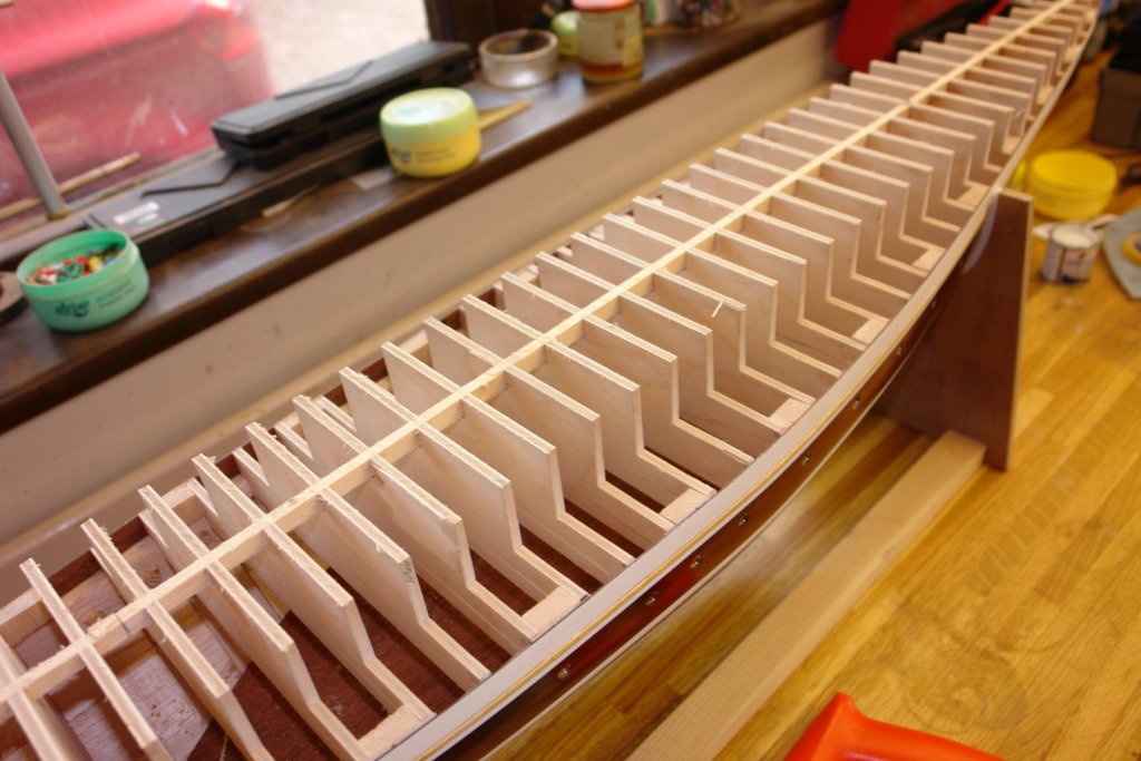
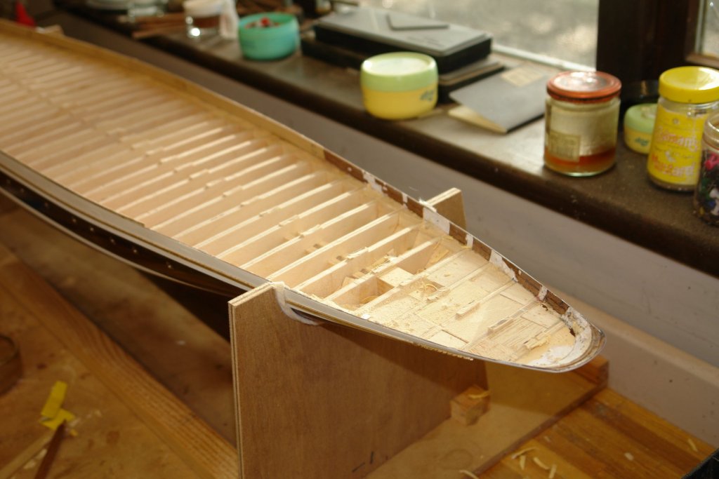
Thank you Druxey and Valeriy The weather improved which means snail paced progress resumes. I spent some time finishing lining the bulwarks with 1/32 ply. I pre drilled the bulwark penetrations in the ply. I will open the holes in the bulwark planks from the outside and hopefully the pre drilling will leave a clean hole. In any event all holes will have brass insets. I did make a start on the deck. The lines are not an amateur attempt at simulating deck planking. I drew on the grid lines to form a guide for the deck planking which will be applied over the plywood sub-deck. The transverse dimension between centre line and deck edge was transferred from the hull using engineers dividers. I also drew on the positions of the various deck structures. The sub deck is made from 1/32 ply and not 1/16 as previously mentioned. The sad news is my laptop is dead and has gone off to the repairer, fortunately it is still under warranty (I am typing this on tablet). Unfortunately the lap top has all the Germania photos and plans on it. So until it returns progress will be curtailed even further.


-
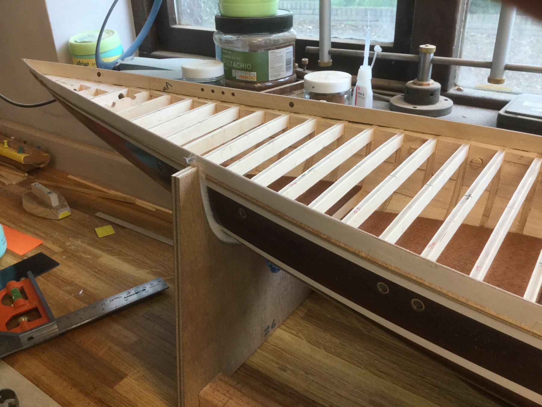
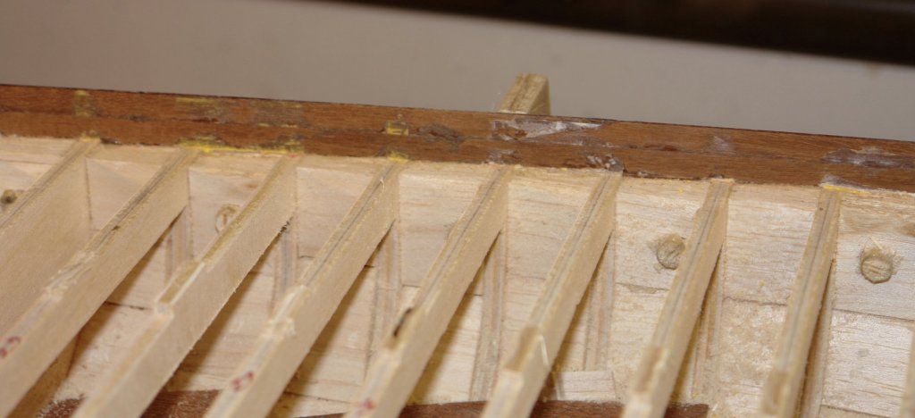
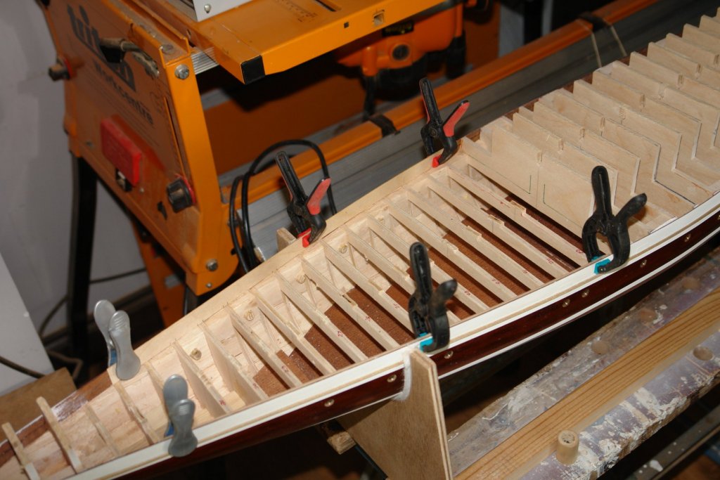
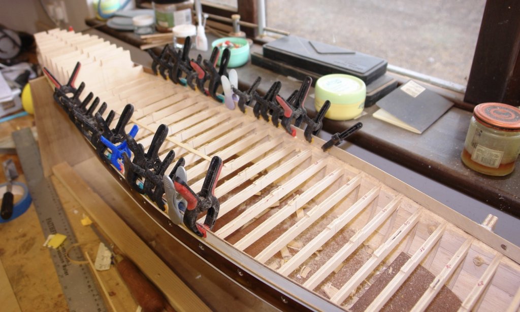
Eberhard The bulwarks on Germania are an extension of the steel hull. I'm not sure of the thickness of steel used but I would guess it is 1/8 to 3/16 inch. At 1:36 scale this equates to about .004" to .006". I think you would agree that this isn't really a feasible thickness for planked wooden construction. The thickness of the bulwark will however be hidden under the rail and as such I'm not too worried about it not being to scale. The hull planking was about .055" thick and it made sense to continue this thickness up to the bulwark. The mahogany planking is much stronger lengthwise (along the grain) and of course the bulwark is several planks deep. I felt that the plywood and the PVA intermediate layer would give me much needed additional strength in the vertical plane. The other benefit of plywood backing is that the inner face of the bulwark is going to be finished smooth and painted white. The plywood gives me a good surface without having to resort to excessive sanding.
-
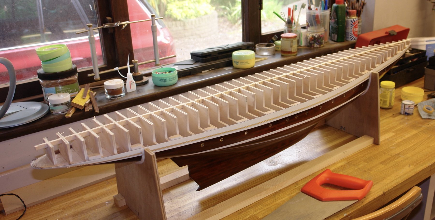
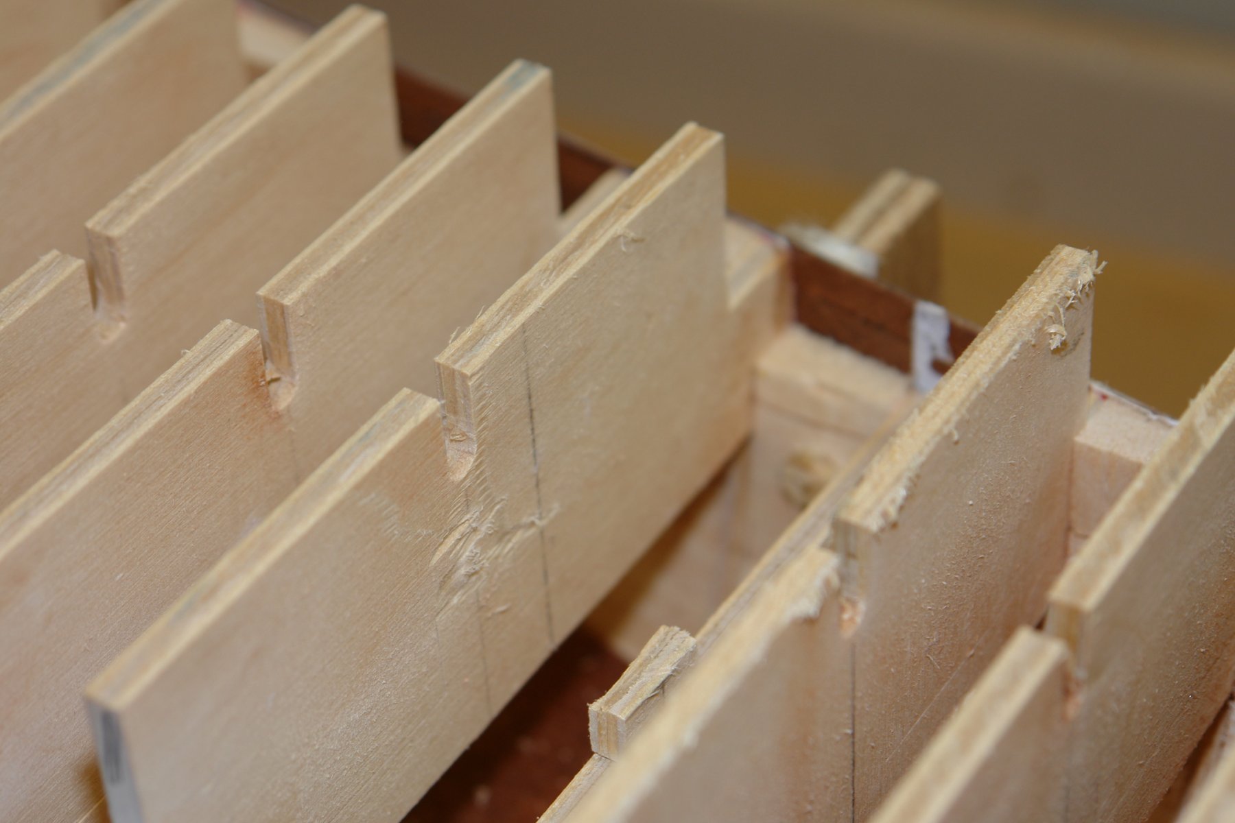
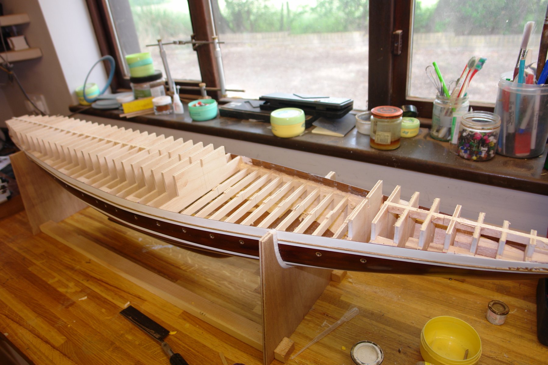
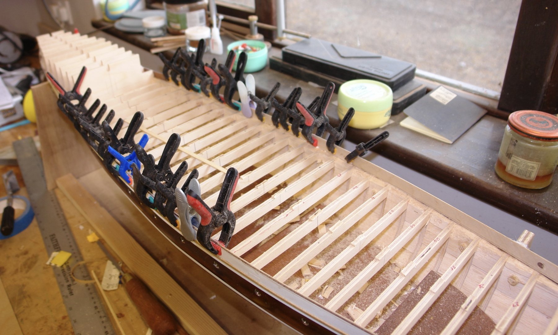
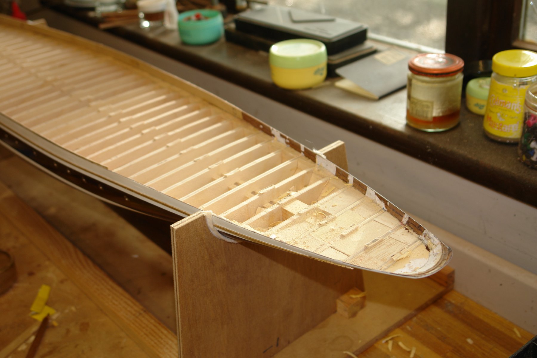
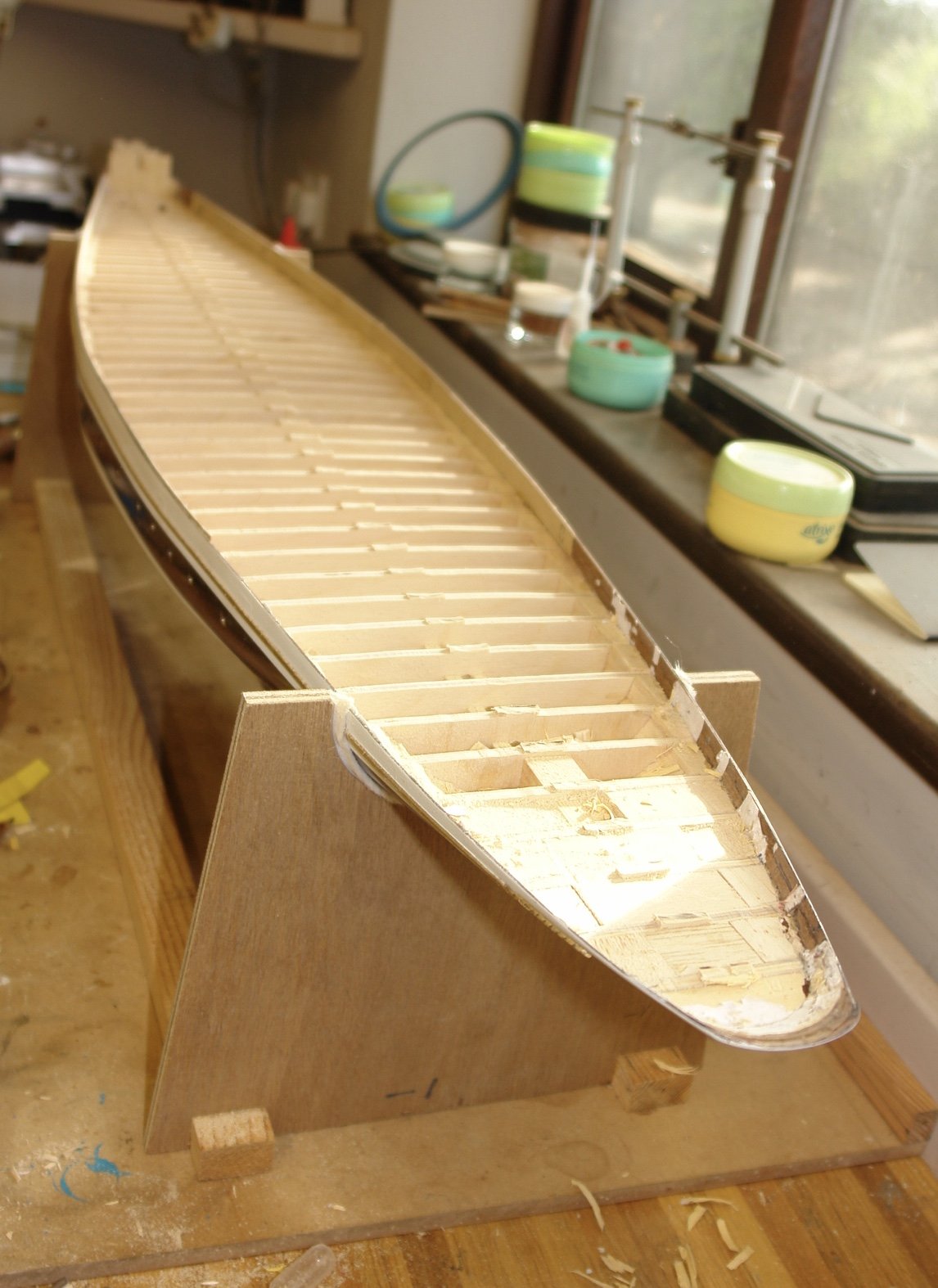
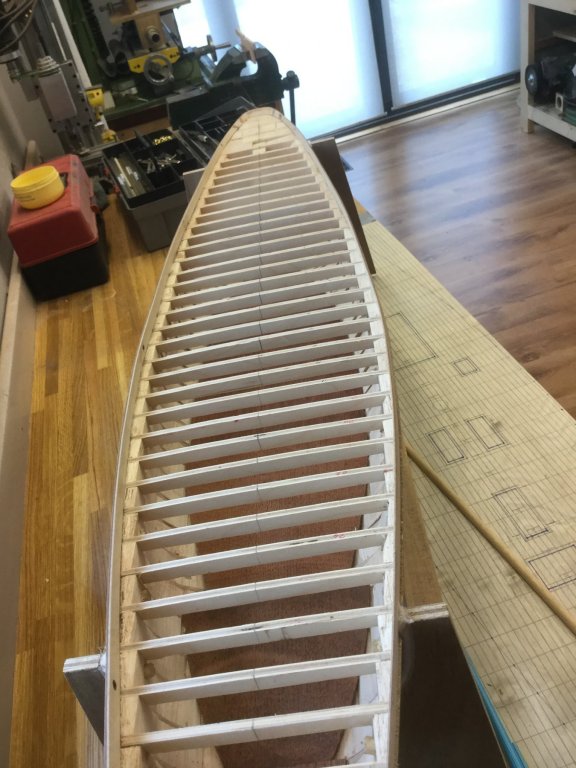
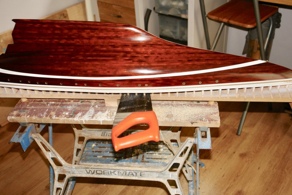
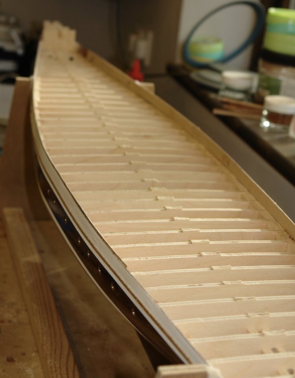
Pat, Druxey, GL, Cortes, Rob, ZBip - thank you all for your comments. After a number of unusual years we seem to have returned to a traditional British summer, rain, wind, floods etc - but fortunately no floods in Sussex. At least the inclement weather has facilitated a few good hours in the workshop. I got round to hacking off the hull from the building board. A fairly quick and painless job with a full sized cross cut saw. You may recall from earlier that I had cut the frames along the deck line leaving about 1/2 inch uncut, I now needed to cut through this 1/2 inch to release the frames. I used 25mm diameter slitting saw blade mounted in my RotaCraft drill (bit like a Dremel) to cut through the retaining web. In the next photo the first up-stand has been removed. The bulwark planks aren't very thick and hence are fragile. Once I had cut through the web I carefully eased the top of the up-stand rearward and the twisting motion broke away the glued frame connection with the bulwark. Again you may recall that I had inserted a piece of paper between the frame and the bulwark planks to form a line of weakness to facilitate removal of the up-stand. In the photo you can see how cleanly the frame came away from the bulwark (white paper residue remains). This technique proved to be a success. I progressed with the removal - a relatively slow job - I need a more powerful rotary tool. In the next photo I have outlined the pre cut deck lines in case my earlier explanation was a bit muddled. It was at about this stage that my daughter paid a visit to the workshop and declared the deck house to be a bit on the large size!!!!!!! I had assumed the bulwarks would be fragile and indeed they were - although a little less so than I had expected. My plan had always been to back the bulwarks with 1/32 ply. Rather than wait for all the frame up-stands to be removed I decided to do the backing in stages. My plan to improve solidity is illustrated in the next sketch. I therefore cleaned up the insides of the bulwarks with sandpaper before gluing on the plywood with PVA glue. The second picture understates the clamps - I actually had one every inch. Some time later i was doing the 3rd and 4th strips of plywood backing - this time showing the clamp forest. I should explain that I pre-drilled the plywood where the bulwark penetrations will be made later. I have virtually completed removal of the up-stands - just 3 left at the bow where I can't get the rotary saw in without damaging the bulwark planks. I need to find a way of removing these. Then I will have to remove the nibs of the up-stands before fairing the frames to take the deck.


-
HMCSS Victoria 1855 by BANYAN - 1:72
KeithAug replied to BANYAN's topic in - Build logs for subjects built 1851 - 1900
John - The Britannia is only south if you are Scottish - moored in Leith - Edinburgh.- 1,013 replies
-
- 5
-

-
- gun dispatch vessel
- victoria
- (and 2 more)
-
I think you must practice a lot. They look perfect to me.
- 306 replies
-
- 4
-
-
- schooner
- la jacinthe
- (and 1 more)
-
HMCSS Victoria 1855 by BANYAN - 1:72
KeithAug replied to BANYAN's topic in - Build logs for subjects built 1851 - 1900
Pat - I have to agree - I live 60 minutes away and have visited many times, I never tire of the experience.- 1,013 replies
-
- 4
-
-
- gun dispatch vessel
- victoria
- (and 2 more)
-
HMCSS Victoria 1855 by BANYAN - 1:72
KeithAug replied to BANYAN's topic in - Build logs for subjects built 1851 - 1900
You did get around Pat - and which was your favourite?- 1,013 replies
-
- 4
-
-
- gun dispatch vessel
- victoria
- (and 2 more)
-
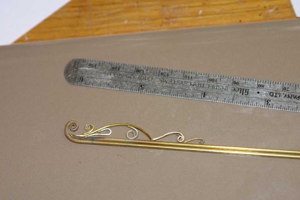
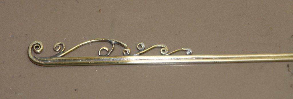
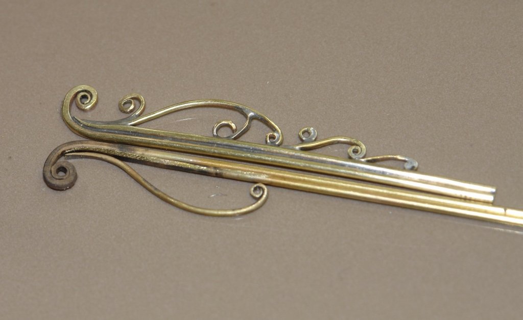
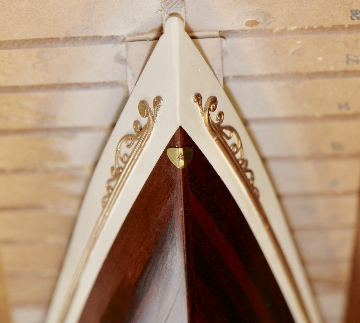
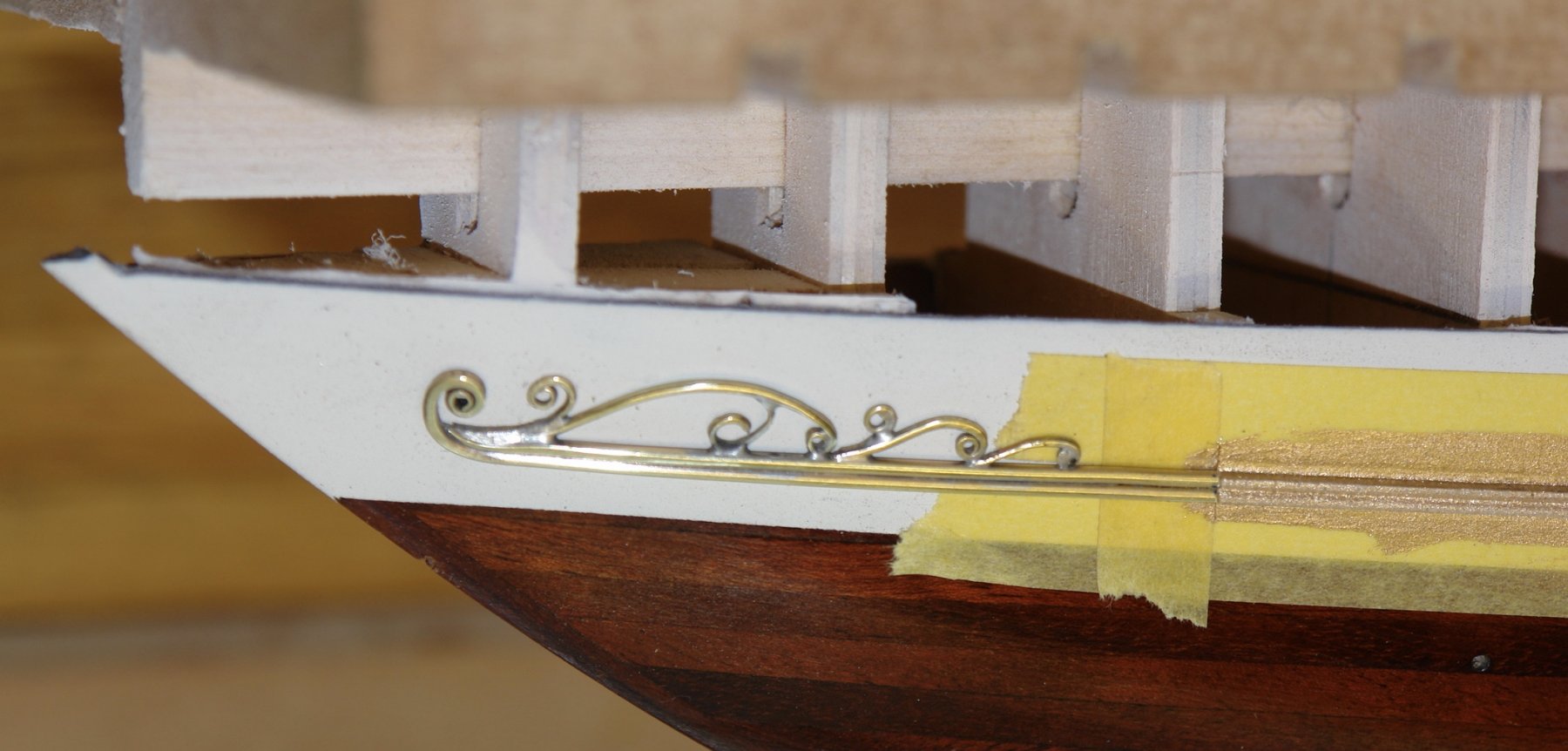
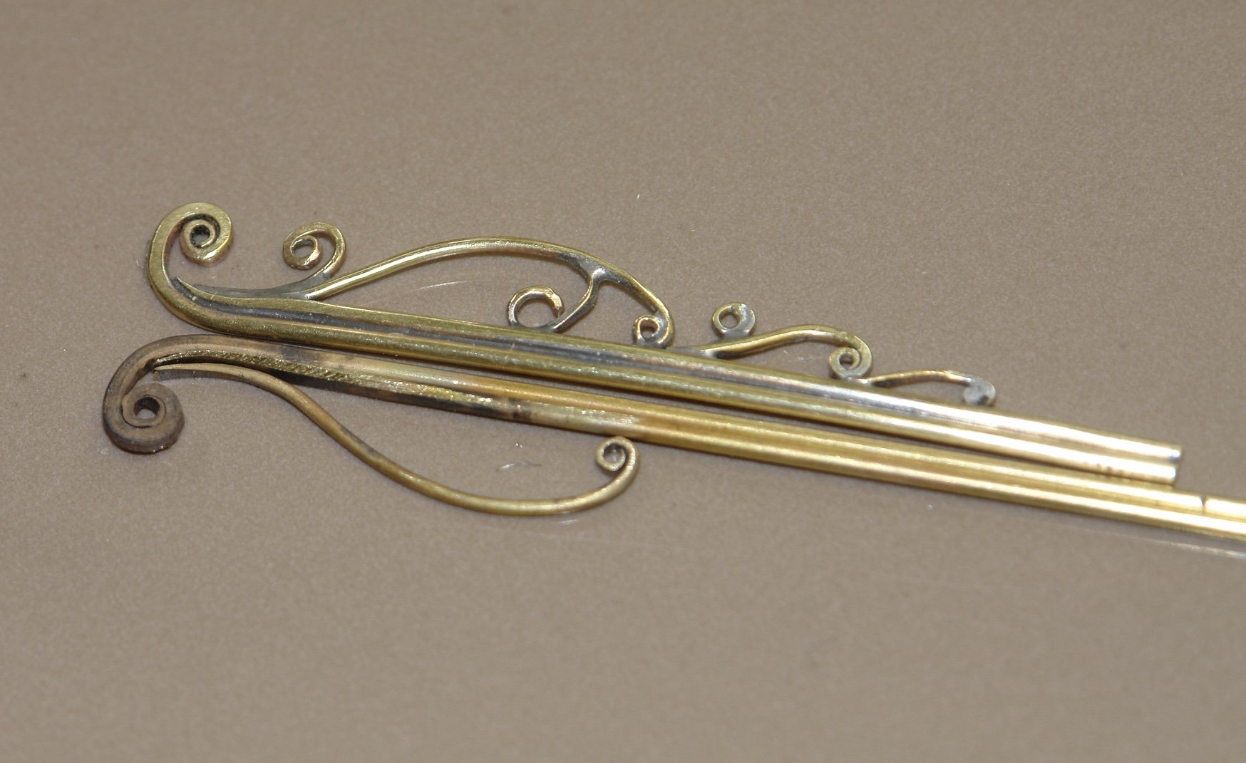
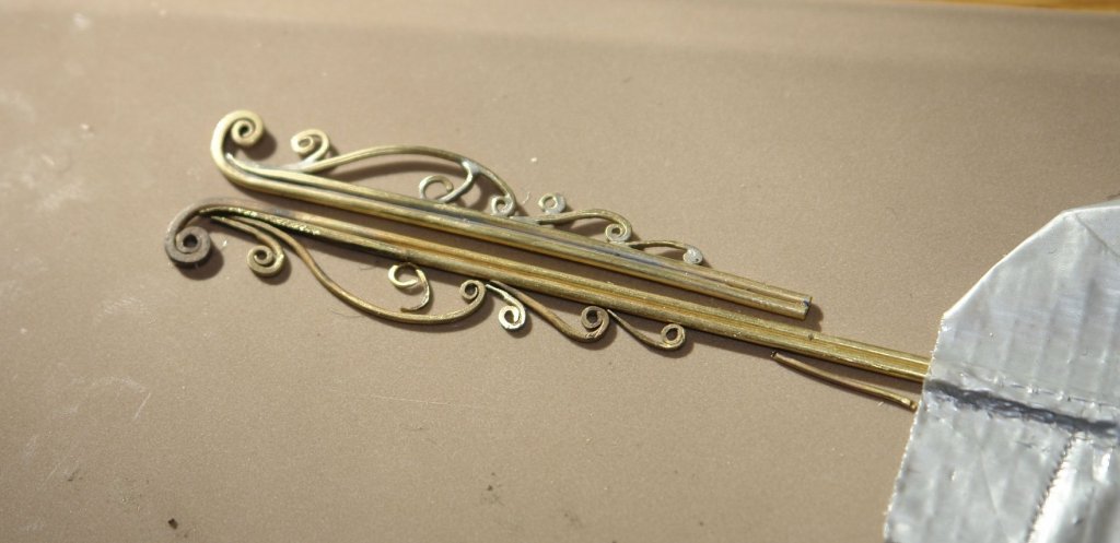
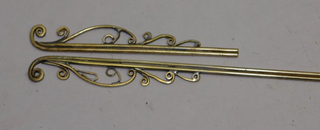
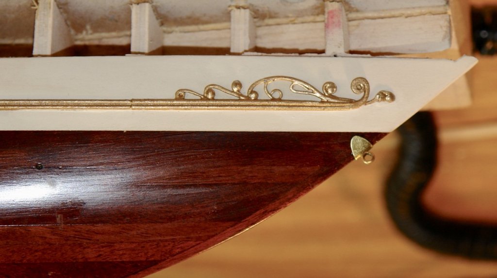
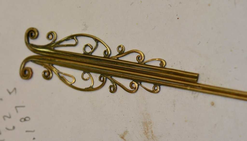
Bedford, Tom, Gary, Pat - thank you for your kind comments and as ever thank you to everyone for the likes. Despite the wet week I have not got a lot done - constructing a bike box for my son and erecting a fence for my daughter sort of got in the way. Not withstanding this I finished the scroll work - that is until I decide I need more detail. The next photo shows the second scroll parts created and positioned alongside the first to check size. This time I soldered the scroll with the missing item from the first scroll added. And then I corrected the first scroll. I made a bit of extra scroll work and the scrolls were then painted with gold paint to match the rubbing strips. The next step was to pin the scrolls in place using brass dressmakers pins and then glued using CA. Finally I did a bit of touch up with gold / white paint. Tomorrow I hope to remove the hull from the building board.

-
Eberhard - I was reading back through some of your machining work - very nice and quite informative. The hull looks smart.
-
Roger - no - to be honest its not one I have heard of. Thank you I will look it up.
- 238 replies
-
- 2
-
-
- leviathan
- troop ship
- (and 2 more)
-
It’s all looking very smart John. I’m looking forward to seeing the planking - what do you intend using?
-
I have to agree that the best holidays of my life have all involved the USA National Parks - some more than once. Unfortunately I have now done virtually all of them and the only unfinished business is Death Valley. We did attempt it once but unfortunately it was closed due to flooding!!!!!!!! Love the detail on the foredeck Dan - i particularly liked the detail on the chain break.
- 238 replies
-
- 6
-
-
- leviathan
- troop ship
- (and 2 more)
-
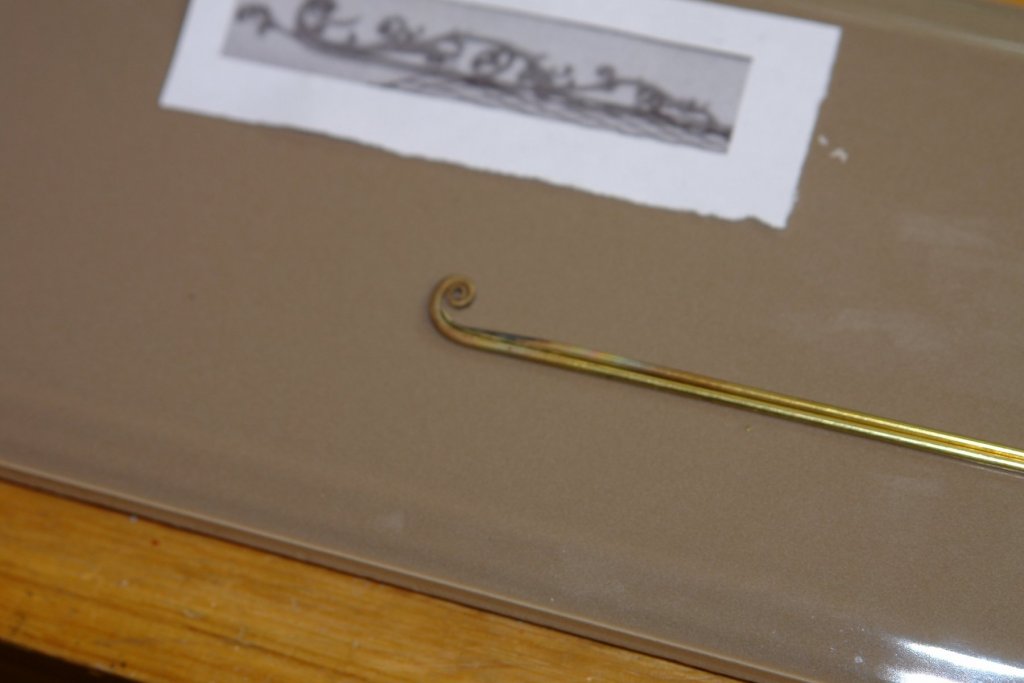
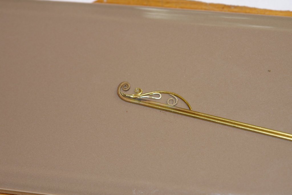
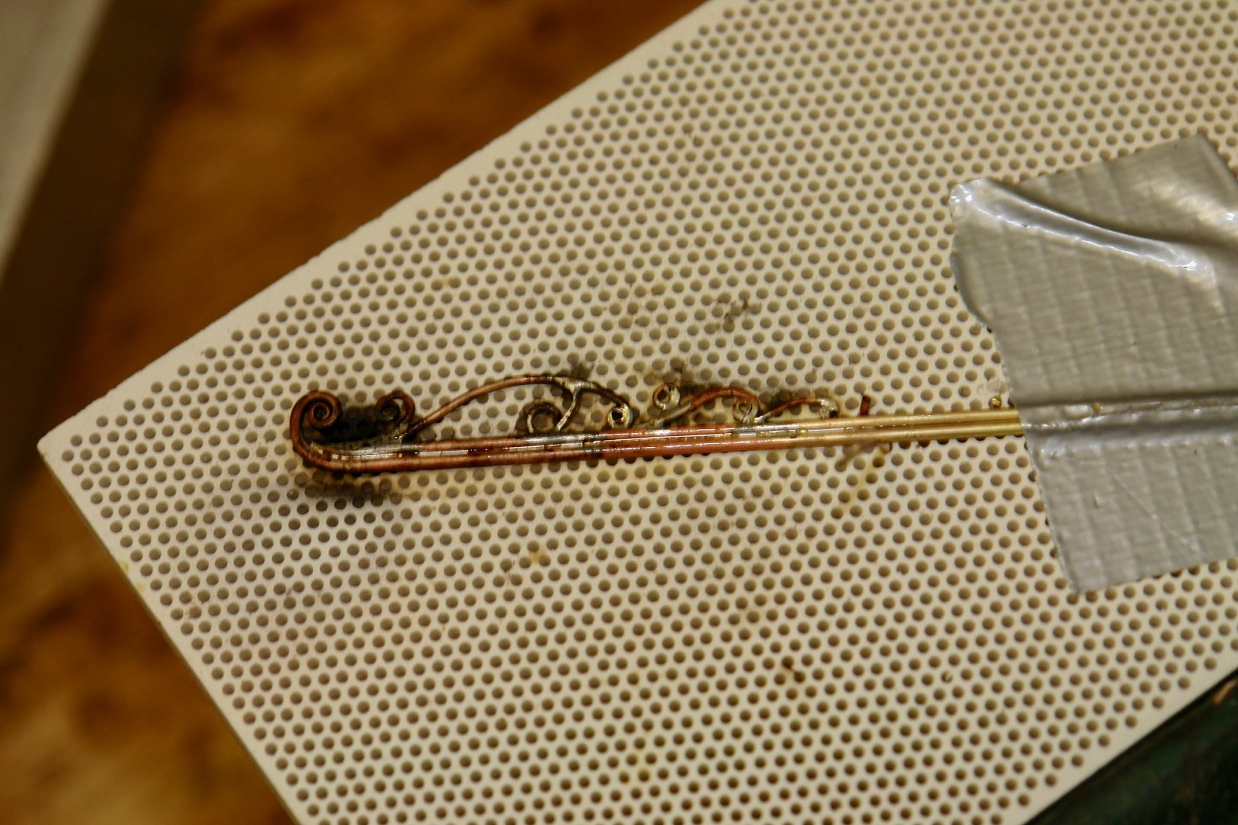
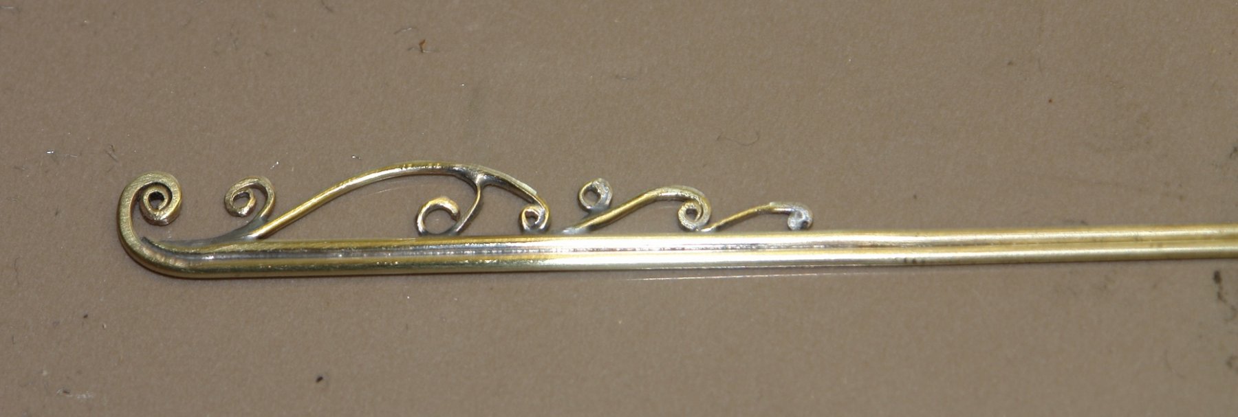
Roger, Patrick, Dan, - thank you for your interest and comments. Michael - thank you and good to see you back. Mark - thank you, the colour is pure white - looking at the photo I see why you asked the question. I think it must be a photographic effect. I have had a few attempts at the scroll work. I started with Fimo but quickly gave it up, much too difficult (at least for me) to get the the thin strands to stay where I wanted them. I decided to have a go at using wire - which involed a deal of scrap white I learned the best way to do it. I started with 2 lengths of .040 brass rod. The first I hammered into a fine taper at the end - assisted by a number of annealing steps. One more annealing and I rolled the coil using a pair of needle nosed pliers. The second was hammered into chisel ended taper before being shaped to nest against the rod - again I employed a number of annealing steps. I used a blown up print of one of my Germania photos as a basis for building the scroll. I then started bending other scrolls from .031" brass wire. Again hammering the ends to tapers as required to blend into the joining surfaces. The larger curved piece was later replace with reshaped part. Other shapes were created and added - some of the finer ones out of .025" brass wire. Bashing wire with a small hammer proved to be quite satisfying. So I carried on......... In the next photo you can see that the largest curved piece has been replace by a similar piece terminating in a coil. The assembly has been soldered hence the mess!!!!! I soldered all the lot in one go by arranging the pieces together and then putting a very small piece of solder at each interconnection. Then I used my wife's kitchen blow torch to heat the lot in one go. It cleaned up quite nicely. I took a file and emery paper to the reverse side to take some of the curvature out of the wire. The observant of you will notice I have mistakenly omitted one of the pieces (idiot). The silver of the solder isn't a problem because the part will be painted gold to match the rubbing strip. I cut the piece to length and then bent and twisted the part to mach the curvature of the hull. In the next photo it is just lying on the hull - the photo has been inverted to show the final orientation. I then started to build the second one and at this stage found the missing bit. I gave up and had my dinner.