KeithAug
-
Posts
3,985 -
Joined
-
Last visited
Content Type
Profiles
Forums
Gallery
Events
Everything posted by KeithAug
-
Peter. I have seen both pale and the more yellow boxwood - seen in your photographs. If you are anything like my age you may recall the wooden foot rules from school. These were invariably made from boxwood and my recollection is that they were generally the colour in your photo. The real question is what effect you are trying to achieve on your model and whether the darker colour is a problem. I keep this as a handy reference as to the more common woods to use...........http://modelshipbuilder.com/page.php?49
-
 Patrick, he could consider flogging his art collection and investing the proceeds in a sensible / stylish classic yacht. I see he / she isn’t into classical art. I’m not really surprised!!!! You need to find the crappy photo setting on your camera, it is great for washing out the detail. All my cameras come with this as the default setting. Amazing detail, just love it.
 -
Mark / John - you both make plausible suggestions. Whatever the reasoning it is still in a vulnerable position and somewhat weaker than it need have been. Maybe people with millions to spend don’t worry about repair bills.
-
Druxey - yes you make a good point. It is all low tack tape and the edging tape is Tamiya tape but never the less I agree it should not be on for more than a few days. Hopefully the airbrush will be here on Saturday and at 3 coats a day I should have the paintwork finished by late Monday.
-
Eberhard - Yes I agree. As I look at more of the detail I find a few things that are not as I would want them. I wonder if some of the build was compromised by rushed design or build. With particular respect to the rubbing strip, clearly any discontinuity weakens the strip itself and introducing vertical edges provides opportunity for the strip to be caught and pulled off when rubbing against the dock. Like you I can not remember a yacht that I have been on where the rubbing strip is compromised in this way.
-
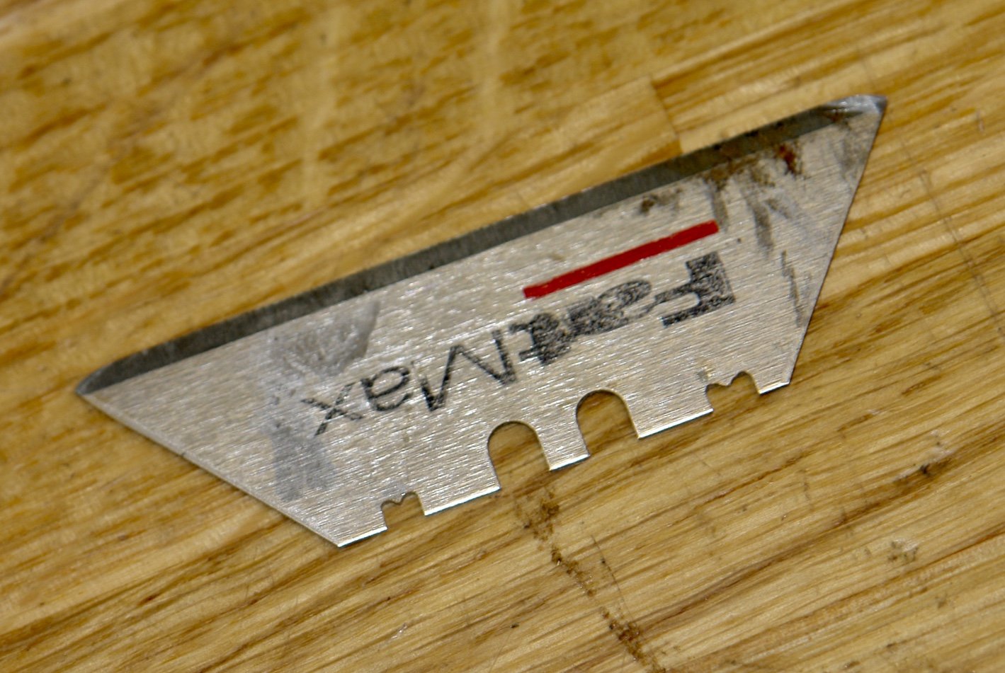
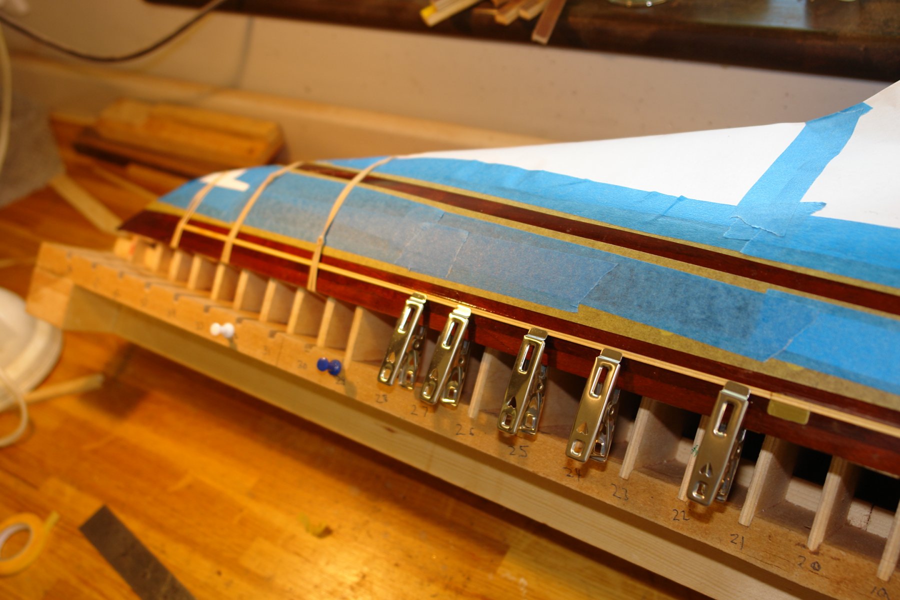
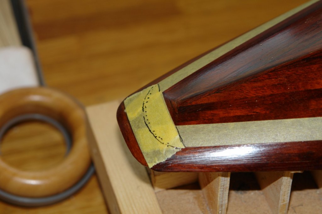
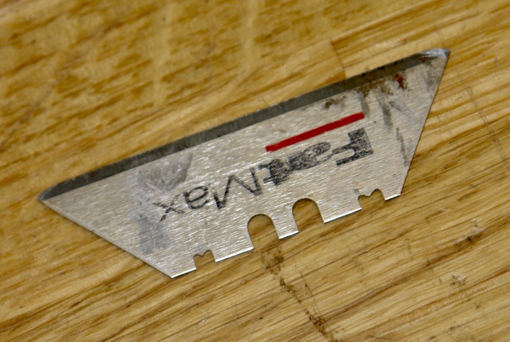
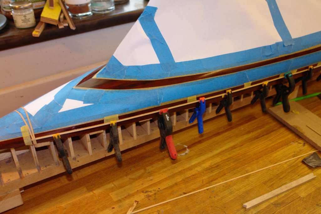
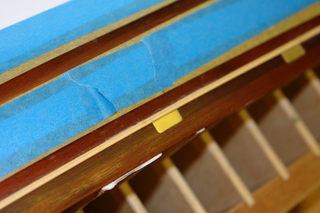
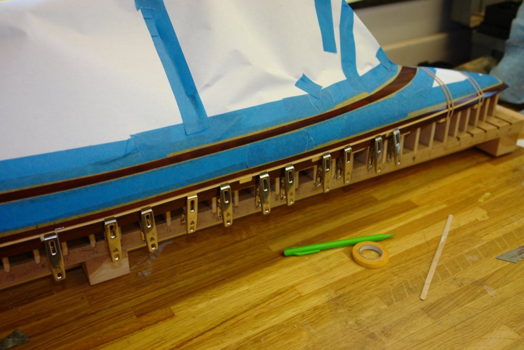
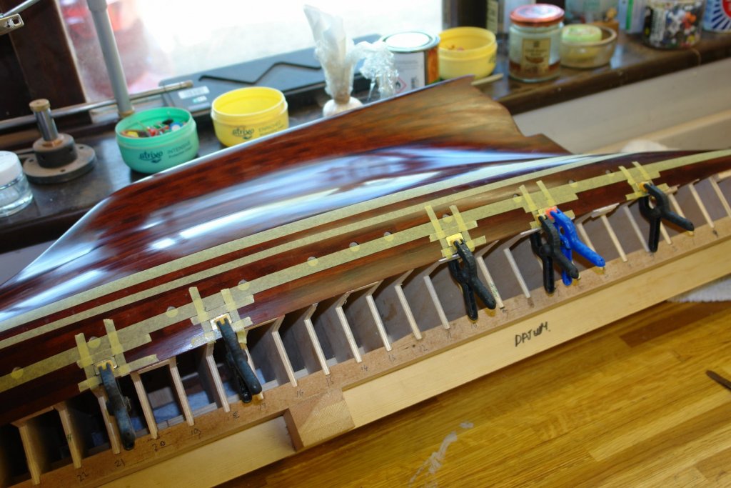
Before making the rubbing strip I completed the bulwark stipe masking at the stern. The rather rough marking was improved by removing the tape, smoothing with a french curve, cutting and then replacement. As far as I can tell the rubbing strip is of double "U" profile. I used the back edge of a box cutte blade for the scraper. Profile notches were cut in with a grinding disc mounted in a craft drill. I did this twice, the wider notch on the right proved to be too wide. The one on the left is .090" wide and this looked more in scale when offered up to the hull. The big advantage of using the back of the blade is that the blade itself can be left razor sharp for later use....................................................................................................... just kidding, I ground the edge off to avoid slicing my fingers. The strips were made from old Venetian Blind slats - not sure what wood but it has very fine and straight grain. The profile was scraped before the profiled edge was slit off on the circular saw using a .031" slitting saw blade. The strip was .050 thick (1.8" at full size). the rubbing strip fully overlaps the bottom edge of the scupper doors and hence is cut to allow the doors to open. The back of the rubbing strip had to be relieved to fit over the scupper doors. The strip was offered up to the hull, the scupper positions marked and then the relief scraped away using a box cutter blade. I also took the opportunity to mask off the remainder of the "not to be painted" hull. The rubbing strips were then clamped in place following the line of the deck edge (the lower edge of the lower bulwark plank). With the strips clamped in place a thin bead of CA glue was run along the edge and allowed to weep behind the strip by capillary action. A fine line was then marked at the scupper sides using a craft knife. I have ordered a replacement airbrush to replace some cheap ones bought with the compressor. When it arrives I will get on painting the hull.

-
A interesting project Zbip. I particularly liked how you approached problem solving. The below decks gear is very neatly done.
-
Mhkash - looking good - what wood are you using for the second layer of planks?
-
Always a pleasure to catch up on your exquisite work.
- 306 replies
-
- 7
-

-
- schooner
- la jacinthe
- (and 1 more)
-
I look forward to Danday. The quality of the original photos is very good, you must have found them very helpful.
- 238 replies
-
- 4
-
-
- leviathan
- troop ship
- (and 2 more)
-
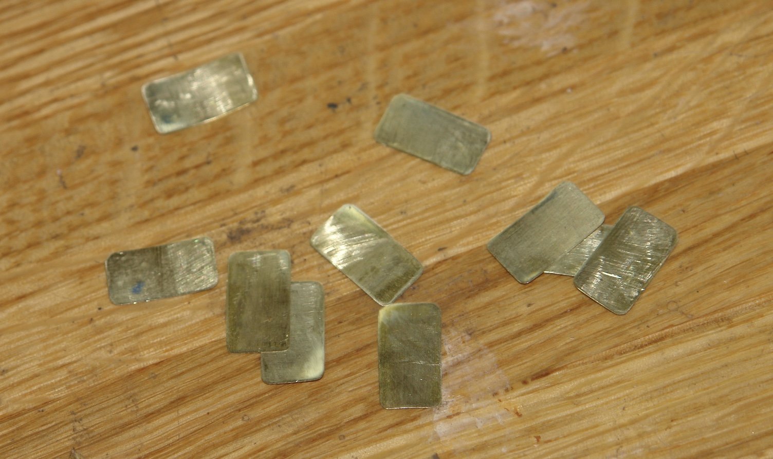
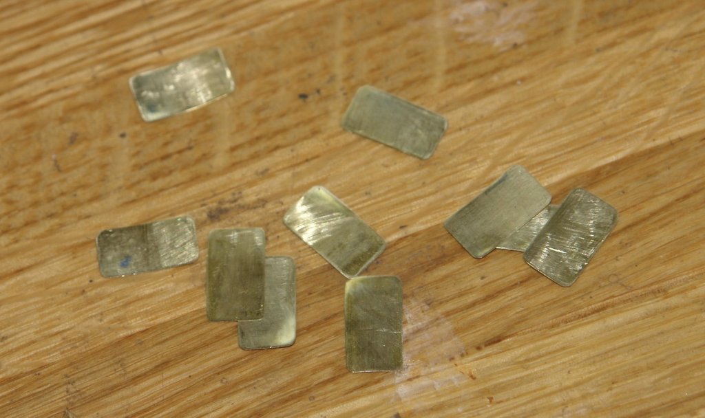
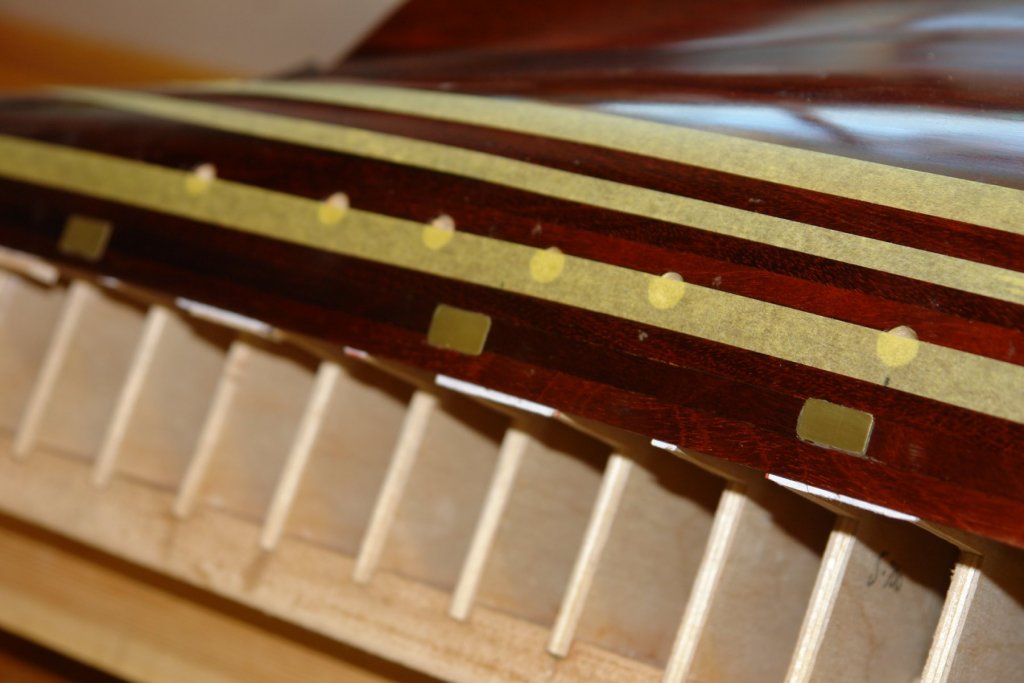
Hello Pat. I did consider making a template (hole in a piece of brass sheet) and then scratching the lines into the hull. I worried however that I would make a mess of it. I din't consider pencil lines but I would be concerned that they would degrade over time with cleaning. Yes Vossie - feel free to cancel the contract! Vaddoc - thank you for looking and the positive comment. I decided my preferred approach to the scuppers was to cut the doors out of .004" soft brass sheet and surface mount them. The scale protrusion above the hull is .150" and I think this will give me the barely visible look I am looking for. The doors were scaled form the plan and cut out using a craft knife - a few passes with the knife did the trick. The corners were then rounded with 600 grit wet and dry paper. The brass was easily distorted and I flattened it by applying force with the wrong end of a 10mm reamer while pressing the brass into a piece of MDF. I needed 10 doors - 5 per side. I marked out the position for the doors using masking tape. The positions were scaled from the plans. Using masking take had the benefit of masking the hull from any inadvertent spread of glue. The doors came out gently curved which helped as the concave side was put on concave face towards the hull. Applying clamping pressure ensured that the edges were forced hard against the hull. They were glued in position using 5 minute set 2 part epoxy. I chose epoxy to give a little adjustment time. The scuppers look very obvious in the next picture but I am expecting them to "fade" with the application of the matt white bulwark strip. The next job is to make and mount the rubbing strip. This is profiled so i need to make a profile scraper.
-
Mark, Looking lovely and a very attractive base - very interested how you go about the support cradles.
-
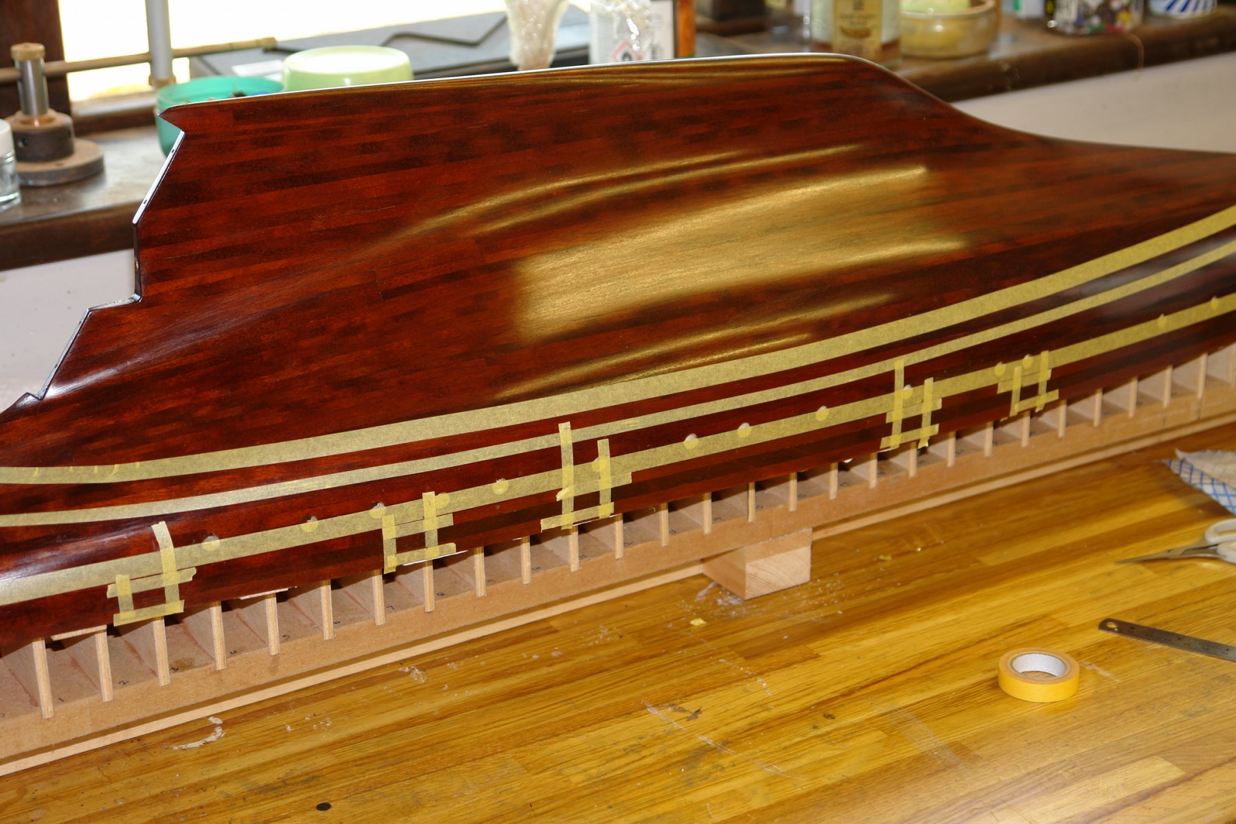
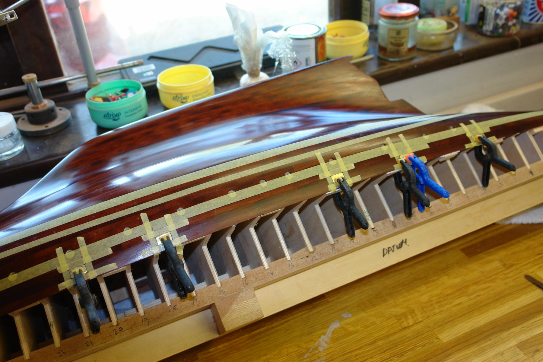
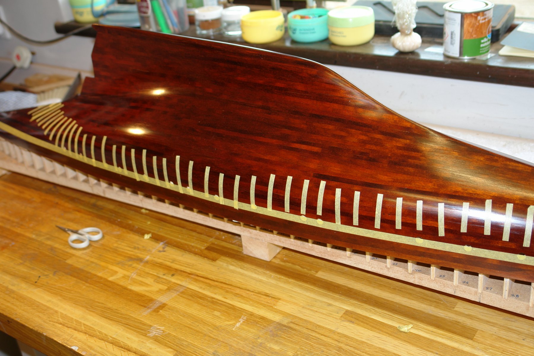
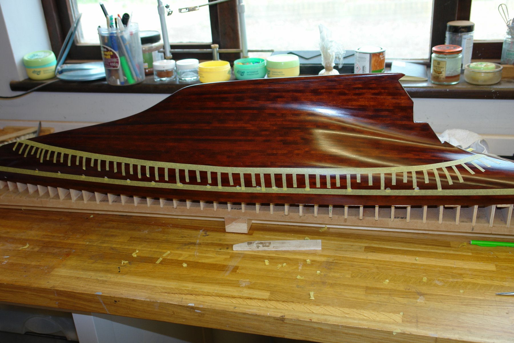
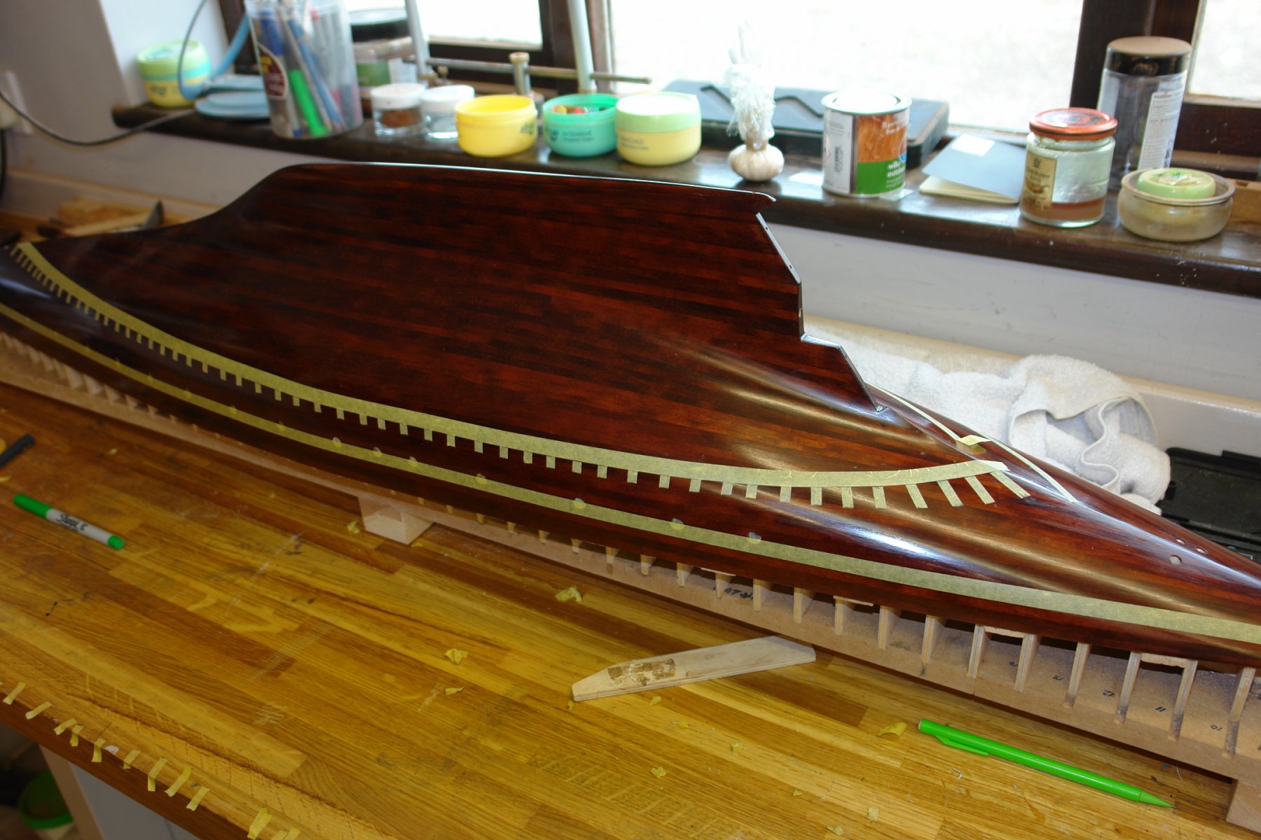
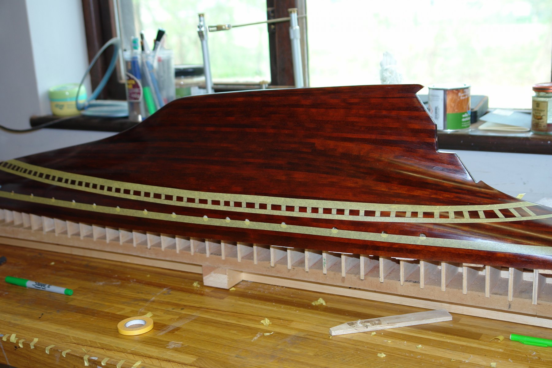
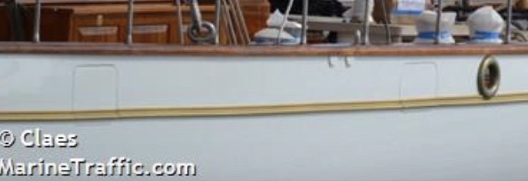
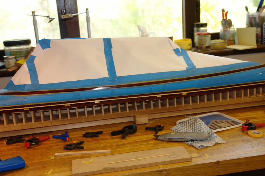
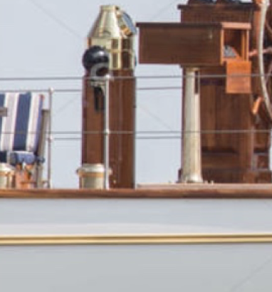
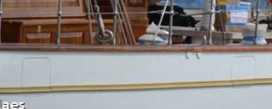
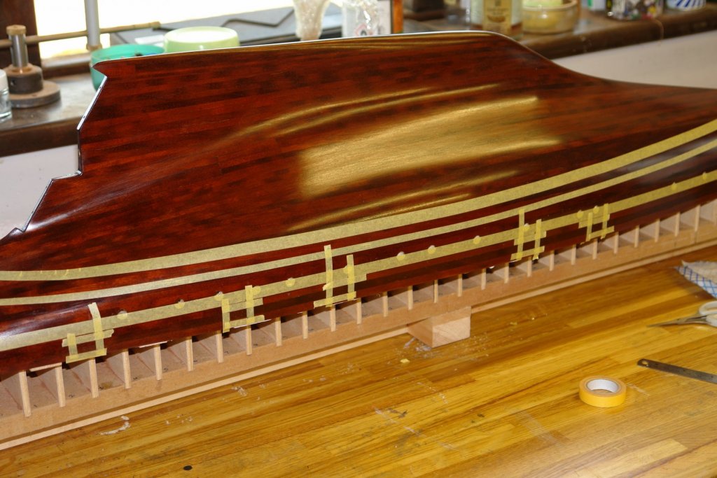
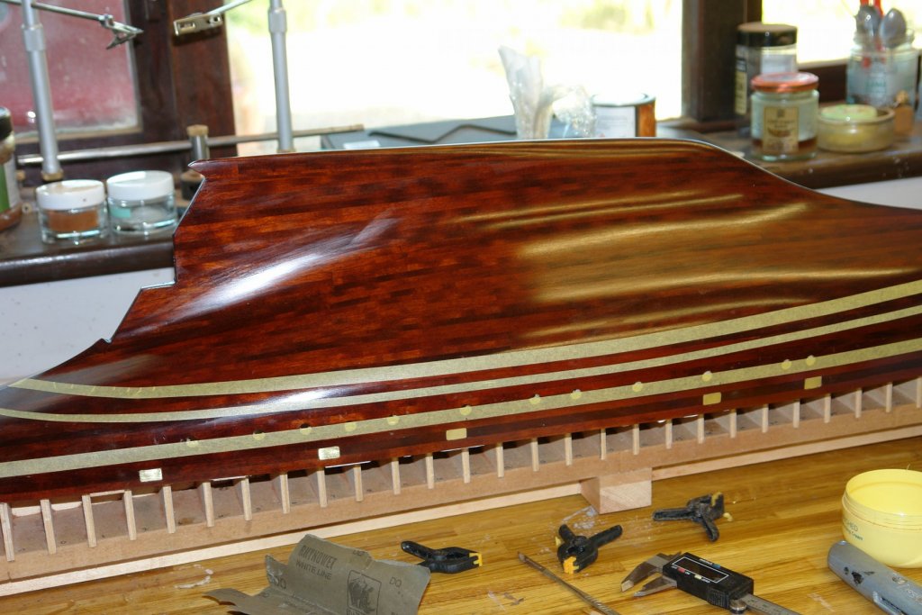
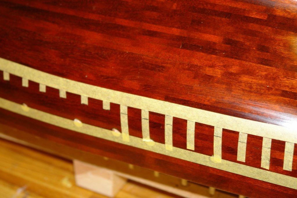
I have been away for a few days and gardening duties are taking more time - hence not a great deal done on Germania. Over the course of about 5 hours I made 4 final decisions on the hull paint scheme, needless to say all the decisions were different. In the end I decided on the minimalist approach advocated by my wife and daughter. I could have toughed it out but the white flag seems more sensible. The final decision is for a waterline band and a bulwark band - both in white. I made a start on masking up the hull in preparation for airbrushing. The first line of tape to go on was fairly easy and followed the bulwark plank at the deck line (the plank edge was still visible beneath the varnish). I don't have a decent laser level so the waterline band was marked out with the traditional pen in a surface block method. I tried a few pens but none would produce a easily visible line against the dark mahogany background. To create a surface for marking out I laid a series of vertical bands of tape (at about 1 inch spacing) and then marked the lines on these. Having done this I carefully peeled back the upper (lower) edge and without removing the tape cut it back to the marked line. I then used this as a guide for placing the horizontal masking tape strip. I then repeated this for the lower (upper) horizontal masking strip. Finally I removed what was left of the vertical strips of tape. I now need to decide what I am doing about the scuppers - 5 each side. The scupper doors are not very visible. They hardly show at all on some photos (look below the left hand end of the steps). They are more clear in the next photo. And disappear entirely in the next photo. On the model I want them only to be seen when you are looking for them - so they need to be quite subtle. I also don't want to weaken the already insubstantial bulwarks. Anyway something to think about overnight.


-
Good point Roger. Roger - I don't know about the DC. The replica is of German design but built in a Spanish yard.
-
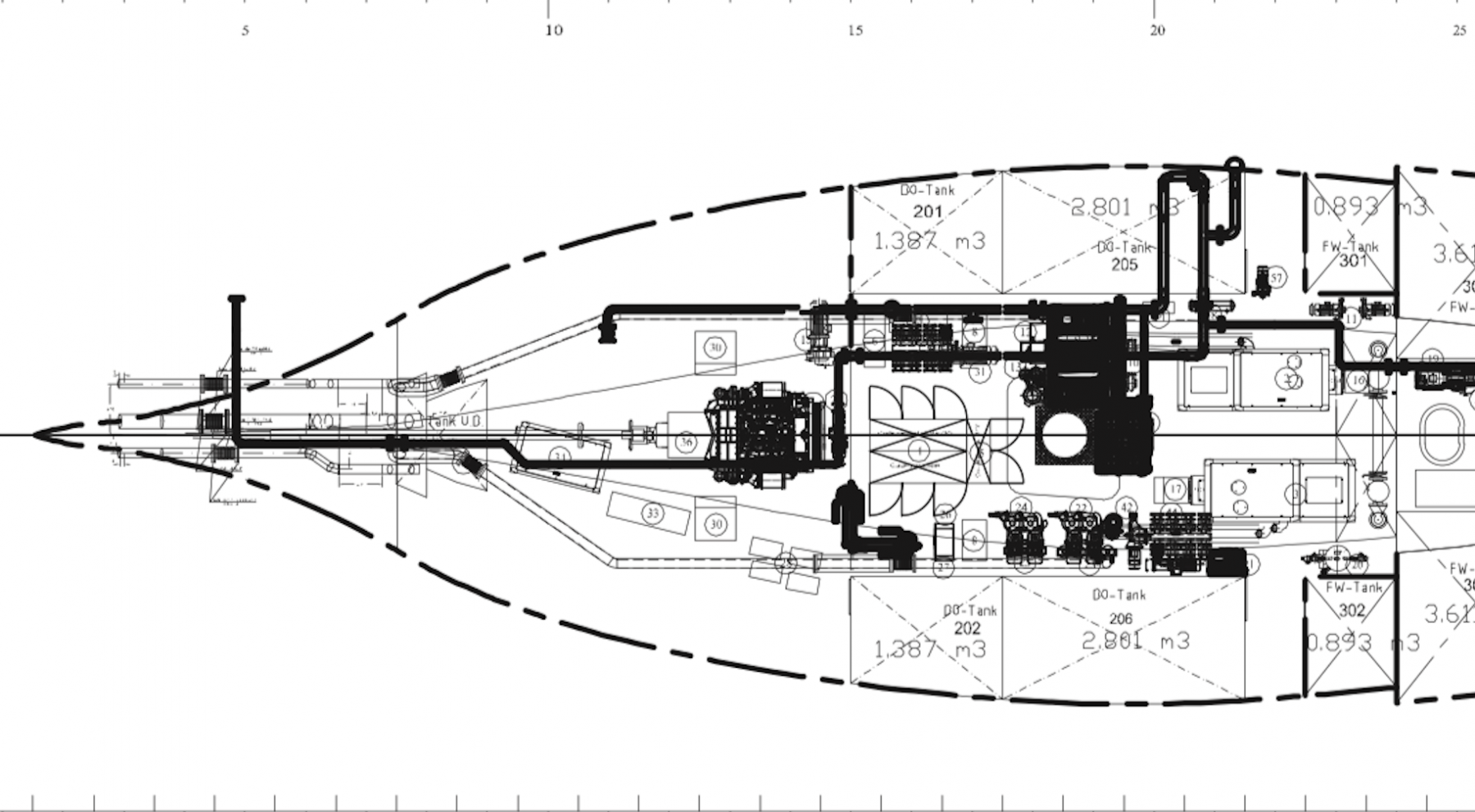
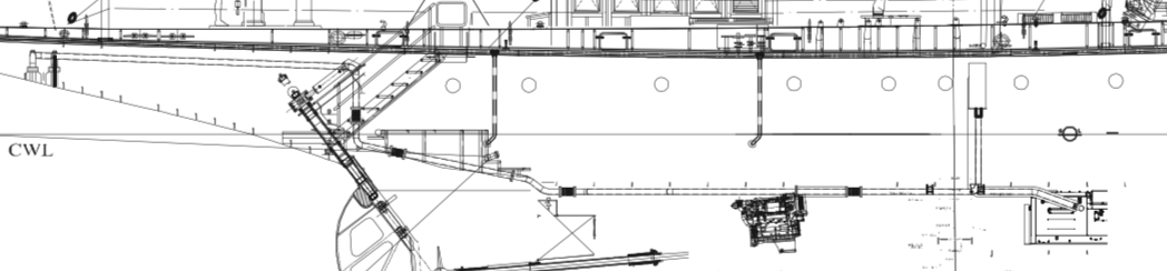
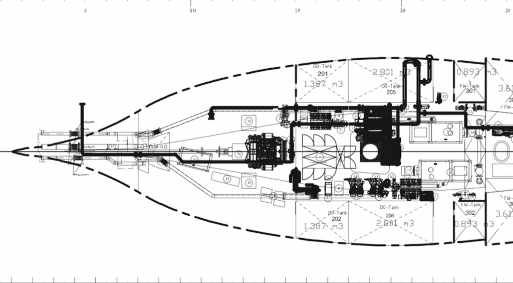
I like that suggestion Sherlock. Prompted by your reply I had another look at the plans. Their appears to be two identical units mounted in opposite directions at the origin of two of the pipes. They do look as though they may be generators. Not sure why two would be needed - either overkill or an owner who cant live without his aircon.
-
Paul - wasn't aware you knew my wife personally! Thanks to all of you who have offered opinions on the holes - I could have provided a little extra information to inform your detective work as follows:- You can see the origin of some of the pipes inside the hull. I don't know what the feature is ahead of the engine but it seems to be associated with 2 of the outlets. Vossie - Thank you - i will try this some time. I wasn't really trying to get a high gloss finish and actually chose a silk finish poly. It just looks a bit shinier than it is under flash lighting. John - I admire the confidence of the motor driven boating fraternity - particularly the ones who put their lives in the hands of single engines that are engineered to meet a price point in someones choice criteria. Sails have never failed me, occasionally they rip - but usually you have more than one to get you home. Engines on the other hand have failed me more than once.

-
Peter, if you start a build log you will find many willing to help and guide. In so far as navigation is concerned let me know what you are trying to do or find and I will try to help.
-
Wonderful Gary - really enjoyed seeing it - Until I studied the post I thought I was looking at some old photos of a real workshop.