


KeithAug
-
Posts
3,267 -
Joined
-
Last visited
Content Type
Profiles
Forums
Gallery
Events
Posts posted by KeithAug
-
-
Hi Julie
I used the backer for a number of reasons:
Because of the thinness of the planks and the wide spacing of the frames I knew the planks would want to curve more at the frames and flatten between them. This would mean that the hull would not change shape smoothly. The lack of smoothness would be greater than could be taken out by sanding - inevitably leading to sanding through the planks as they passed over the frames. The backing significantly reduces / eliminates this problem.
Perfect edge to edge butting of successive planks would be very hard to achieve. This type of butting invariably leaves isolated areas where the planks have some misalignment. A misalignment of 1/2 the plank thickness (only .020 inch) would mean half the plank thickness would have to be sanded away to create a smooth hull. The resulting thinned hull would of course be very weak. The backing significantly reduces this problem.
The backing stabilises the frames meaning you can complete the planking of one side before starting the other. Without backing you need to alternate planks from side to side. This is a more difficult operation because where the planks close at the bow they want to cross.
Although the backing does aid fairing of the frames its main purpose is to address the planking issues identified above.
Keith
- Canute, Seventynet, yvesvidal and 4 others
-
 7
7
-
Julie
Re 2nd planking - realistic mahogany plank lengths.
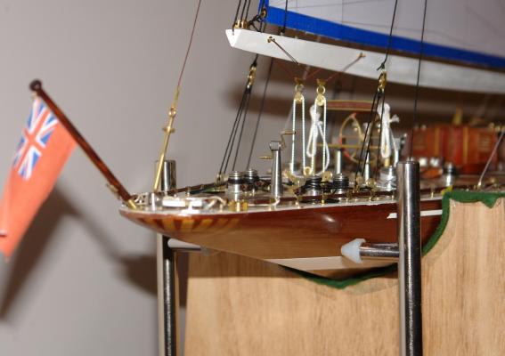
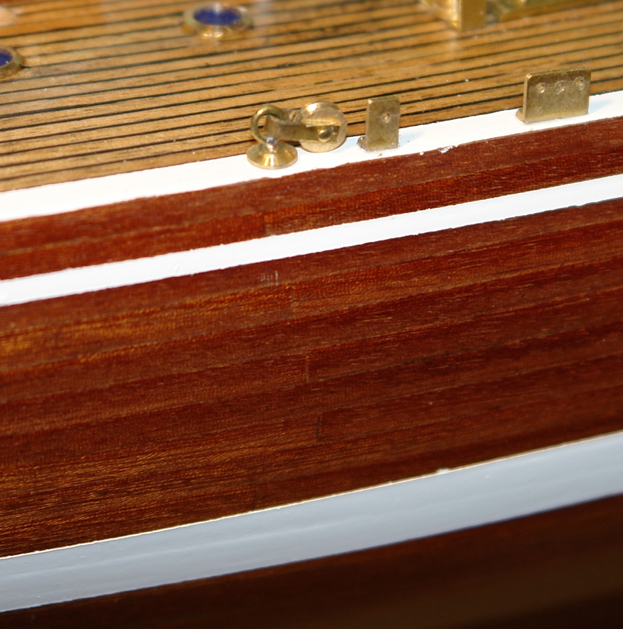
This is my best shot of the end butt on my 2nd planks. This is at high magnification. The end butts are hard to see on the finished model. Shortening the planks to a scale length might actually make the laying of the planks easier. On the other hand it will make it more tedious. The decision on what to do is down to you and what makes you feel good. Long or short planks are both wrong on this model because as you say the hull was metal. As you are not constrained by the accuracy of reproduction constraints my advice is to do what makes you feel good.
- Eddie, popeye the sailor, ScottRC and 5 others
-
8
-
Hi jmcsys
I find experimenting is one of the most enjoyable part of the process - it always feels better when (after a number of failures) something works. Thank you for your comments.
Keith
-
Hi Julie
You seem to be doing very well.
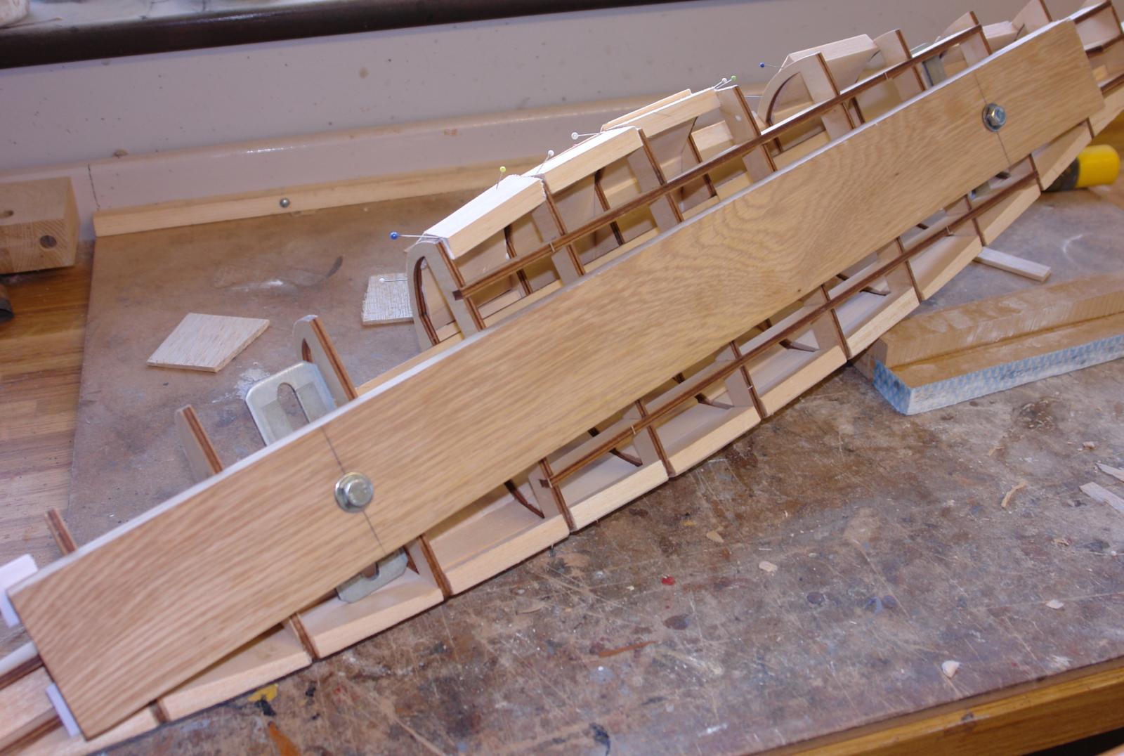
Re frame additions - if I am looking at the right bits these are because in the Amati build method the planks are only long enough to reach about half way along the hull. They have therefore given you a double frame thickness to land the end of the planks on. I don't like this solution as it means all the plank ends finish on this central frame - giving a distinctive line of weakness. Planks which alternatively land on different frames give a more realistic and stronger solution. You may be able to see this in the attached photo.
Keith
-
Hi Julie
Sorry to hear about the glue problems. I didn't experience this so I can't provide much advice. The general purpose wood PVA glue I used did not start to go tacky until about 5 minutes after application, neither did it appear to swell the wood leading to tightening of the joints. It is however water based so I can see that it could soak into the wood causing swelling and tightness where joints are particularly well made. One alternative is to use 2 part quick set epoxy. I used this extensively on my first model for gluing the frames. The advantage is that it does not soak into the timber to any degree and also has self lubrication properties that ease the slipping of parts together. The down side is that it is a bit more time consuming to make up and clean down. You may need to experiment to find the best solution.
Keith
-
Hi Julie
I was trying not to be too dogmatic in my views. I think I will come off the fence by saying that I think tacking the deck on is in general a waste of time and effort. Indeed if the skeleton isn't distorted you may even get away without the need for a strong back. The strong back does however have the added benefit of easing holding / fixing during the planking operation.
I think my kit had been badly stored at some time before purchase as the plywood was bowed slightly when it came out of the box, this led to the distortion in the assembled skeleton. The shim method for the strong back works well.
Happy shopping!
Keith
-
Hi Julie
The strong back contacted forward and aft (on the longitudinal stringers) with a little clearance on the intervening frames. I used spacers at the stern end to take care of the athwart ships curvature. Effectively the strong back was locating solidly at 4 points. This was enough to adjust the slight sideways bow and more pronounced twist in my skeleton without altering the hull fore to aft curvature. You can see from the attached photos that the strong back is about 2/3 the length of the hull. You can also see the spacers (white card) in the bottom left corner.
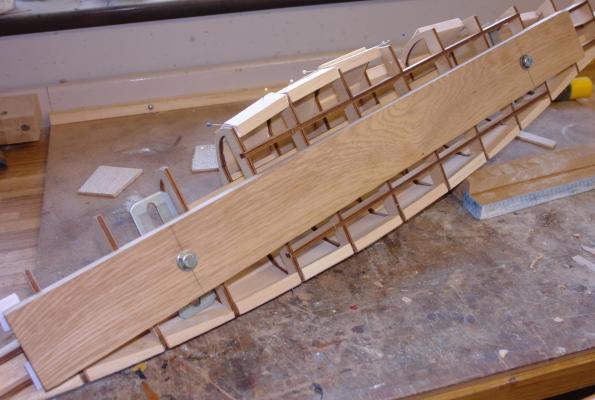
My interpretation is that Amati want you to use the deck pinned in place while the skeleton is glued and thereafter removed while 1st planking is undertaken. This is particularly important with the Amati (unbacked) planking solution as you would need access to the backs of the planks to ease them into edge to edge alignment. This access is available for the initial planks but soon disappears as the planking proceeds, unless of course the deck isn't fixed in place until later.
Keith
-
Hi Julie
My observations on the questions you pose are as follows:-
The round mast bothered me also - particularly as the 1989 Endeavour definitely has an oval mast. If I had thought about it early enough I would manufactured the mast out of a square section core with semicircular dowels front and back and then tapered this. I didn't and made do with a round mast. This isn't ideal but wasn't particularly noticeable on the finished model. Pragmatism over perfection for me in this case.
I din't nail the deck in place as suggested in the instructions. Bolting on the oak plank strong back removed the need for attaching the deck until after I had completed the 1st planking. Having completed 1st planking I cut a dowel of about 1 foot in length and the same diameter as the mast and used this to align the forward section of the deck relative to the frames (similar to what you are doing). With the deck in place (held with elastic bands passed around the deck and hull) I used a square to make sure that the dowel was at right angles to the deck fore and aft. As the deck rises towards the bow this gave a natural rearward rake to the mast. I also used the square to judge that the dummy mast was at right angles to the deck athwart ships. Because of the curvature of the deck the latter operation required equal thicknesses of packing to be placed at the deck edges (to compensate for the curvature). Once I was happy with the location of the dummy mast I drilled though the deck into the frames at a number of locations with a 0.5mm drill. I then removed the deck applied the glue and relocated the deck back in position using dressmakers pins through the pre drilled holes (no nailing required). The deck was held in place during gluing with elastic bands. Once the fore section of the deck was in place the rear section was easily located by butting it up to the fore section.
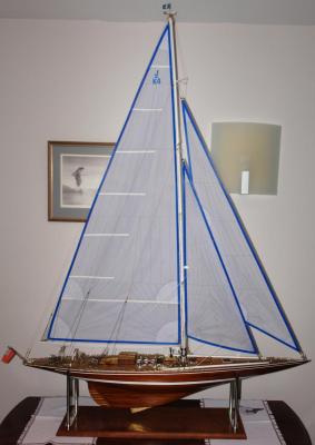
I wasn't content with accepting a straight mast but also wanted to impart rearward curvature in addition to the rearward rake. I did this by using the back stay to spring the mast towards the stern. This of course had implications for the shape of the mainsail at the luff. Hence the templating that I had to do when shaping the sails. My 1989 Endeavour has a fixed back stay as well as pairs of running back stays on either side. The fixed back stay is absent on your 1934 version which relies solely on the running back stays (a recipe for dismasting if you ask me!).
- Eddie, Julie Mo, Dimitris71 and 1 other
-
4
-
Yves
Thank you for you kind comments all the way through this build.
Keith
-
Julie
Re movable rudder - I did consider it but decided not to because of the issue you have identified. Perhaps the simplest solution would be to shorten the rudder by 1/4 inch at the keel end and add the 1/4 inch to the hull to give the extra "meat" required.
Model sailing yachts are far less stiff than the real thing, the way that scale works isn't linear and modellers who convert yachts for RC nearly always make the keel much deeper (and therefore out of scale). It's all to do with a fluid dynamics property called Reynolds Number which is a bit nerdy. They therefore wouldn't have the problem that you identify.
Keith
-
Julie
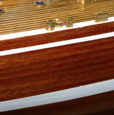
Re your question about how the planking will look at the gunnel line. This is the best photo of the planking that I have. If you zoom in and look closely you can see many of the planks and even some of the end to end abutments.
Keith

- popeye the sailor, mtaylor, IgorSky and 4 others
-
7
-
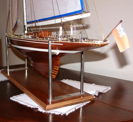
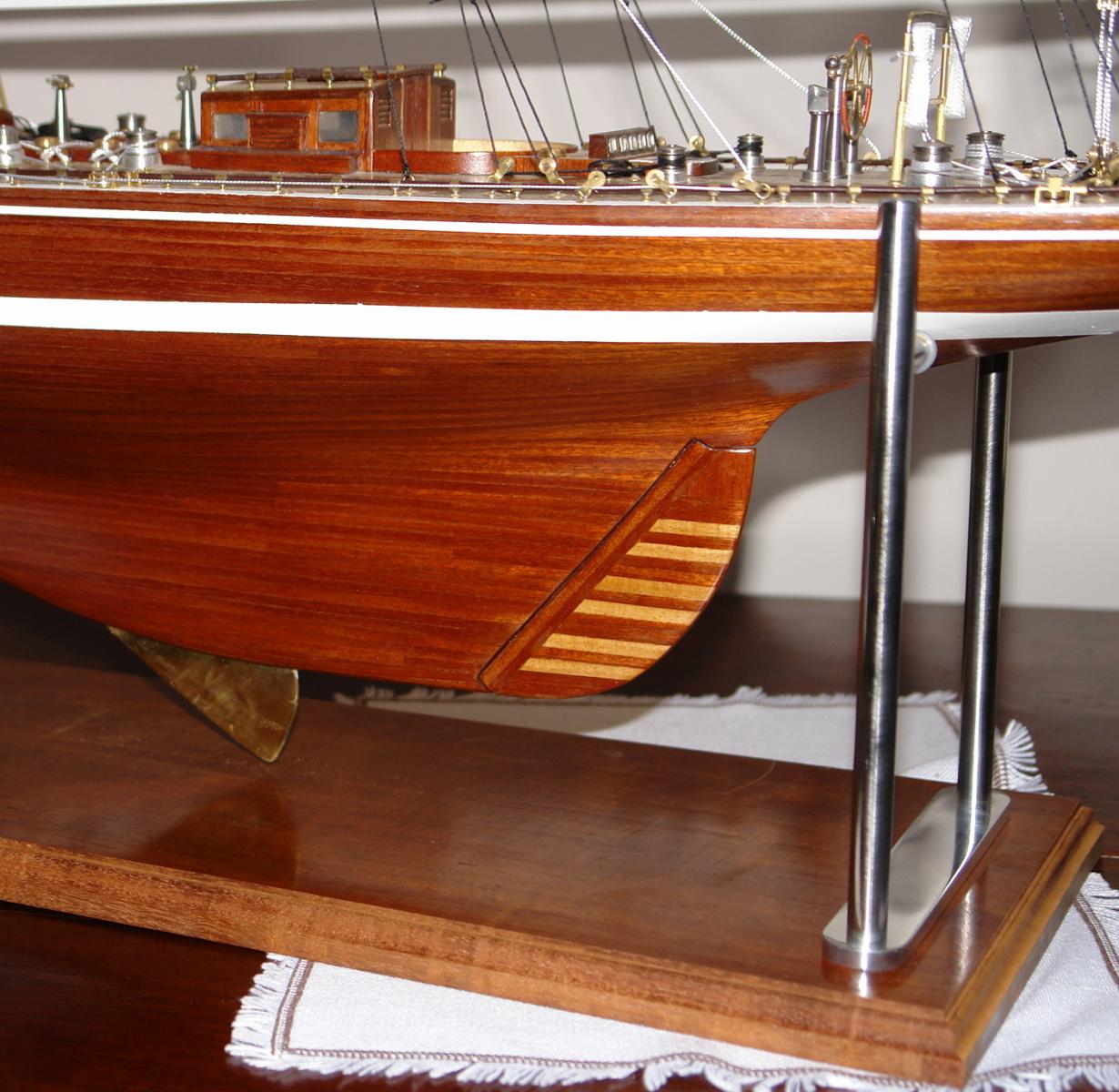
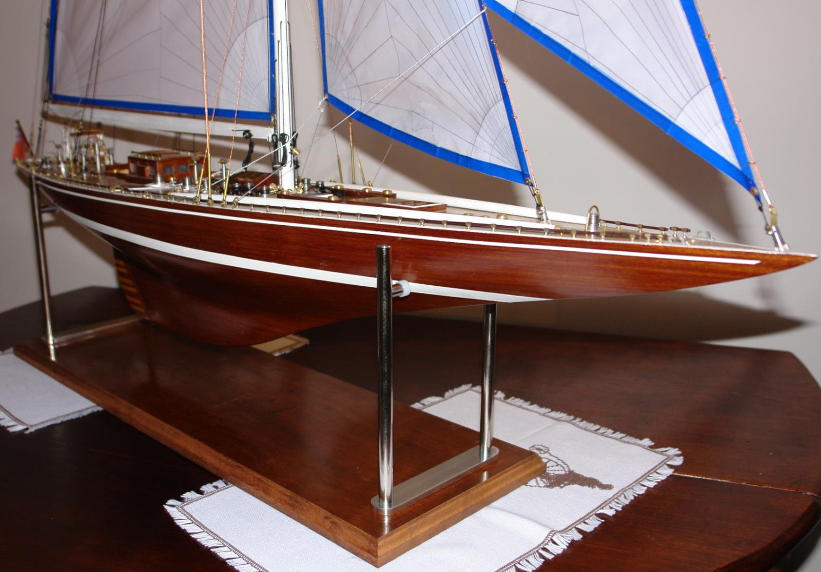
Display Stand Continued.
I toyed with the idea of trying a bit of inlay on the base but decided that the natural wood was better. I did however mill the edges to add interest and give it a more professional look.
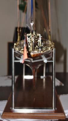
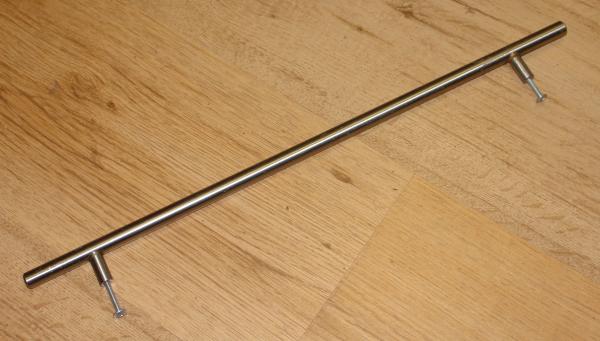
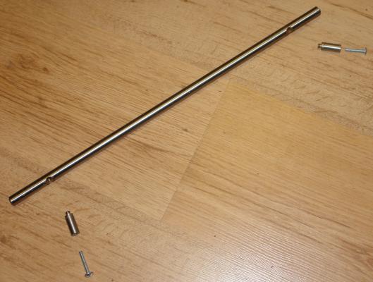
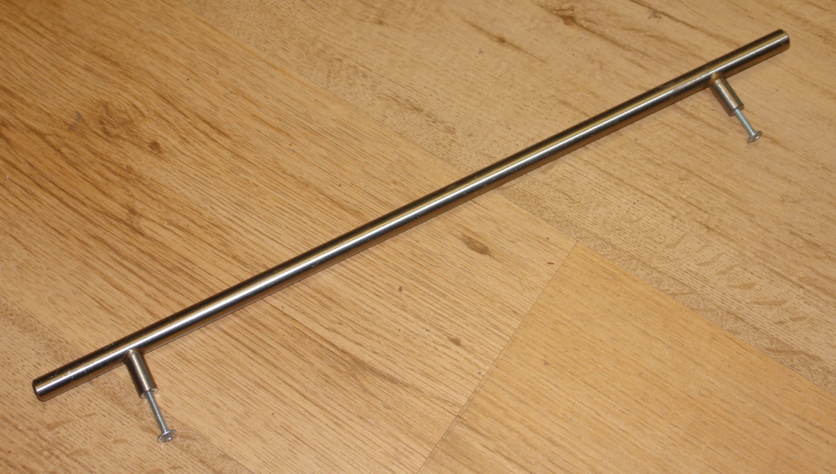
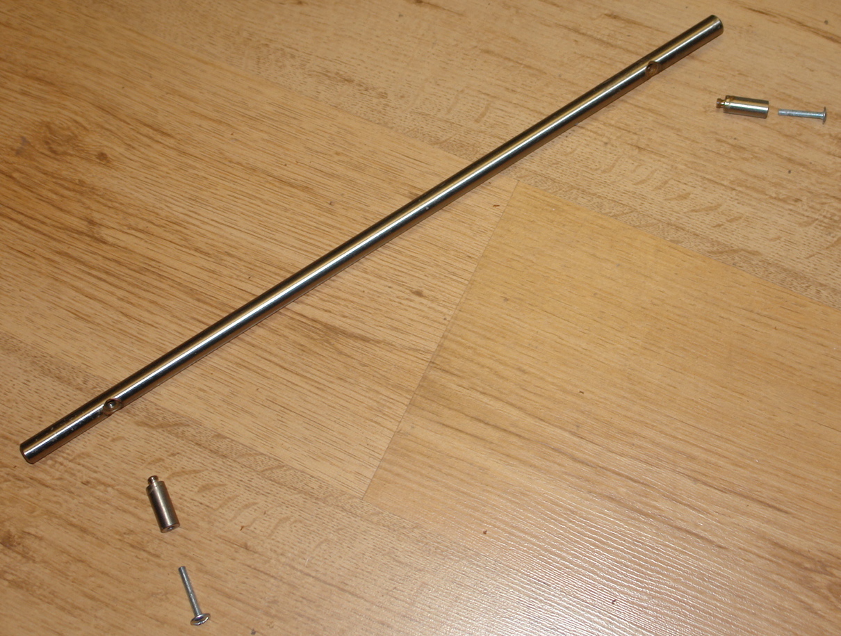
I cut down the door handles to create pedestals. On the end of the "T" I added turned polythene cones. The cones contact the hull and I wanted something pliable to prevent hull damage. The cones are attached by screws and these give a degree of adjustment. This helps with the levelling of the model when displayed.
The bottom of the pedestals are drilled and tapped to take the mounting bolts which locate through the holes in the base. I then polished the pedestals on a polishing wheel.
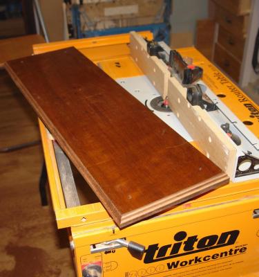
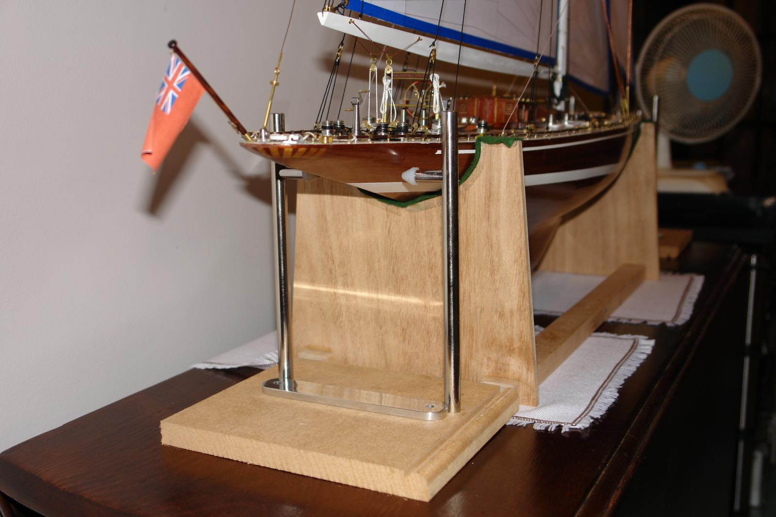
I did an initial check on the functioning of the pedestals by mounting them on a scrap piece of MDF as per the photographs. The check confirmed that the pedestals would give the hull adequate support.
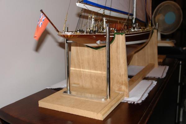
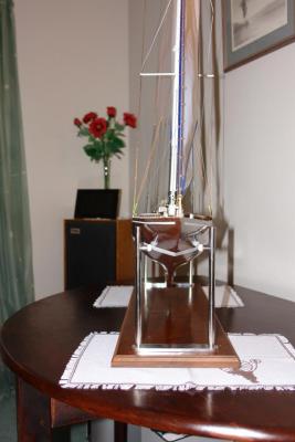
I did find that the base was prone to flexing (splaying of the pedestals). Although the mahogany base was going to be more rigid I decided to add a strengthening strap (visible in the previous pictures).
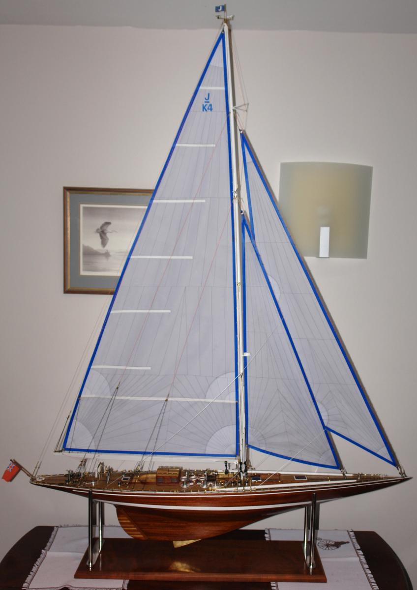
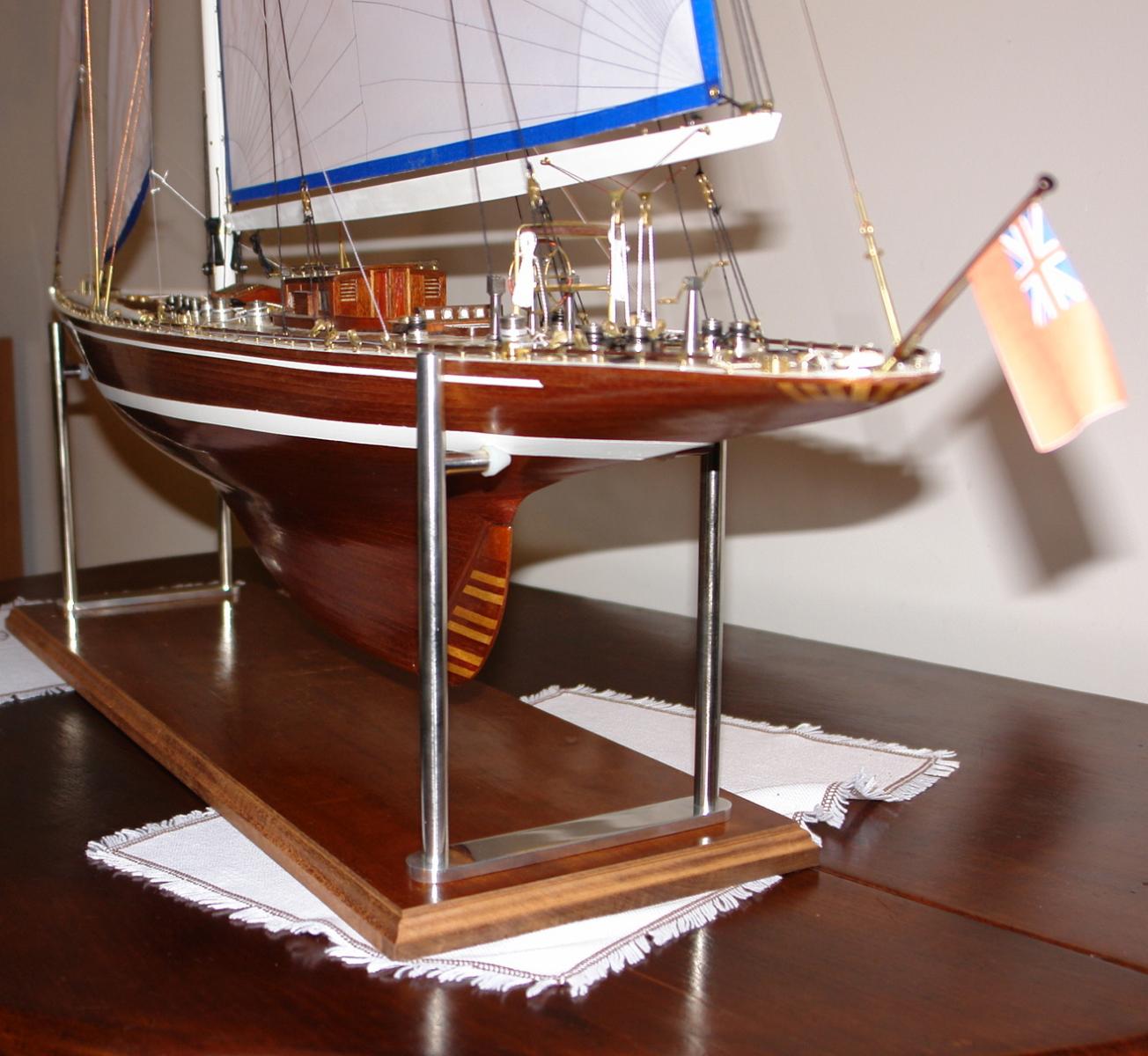
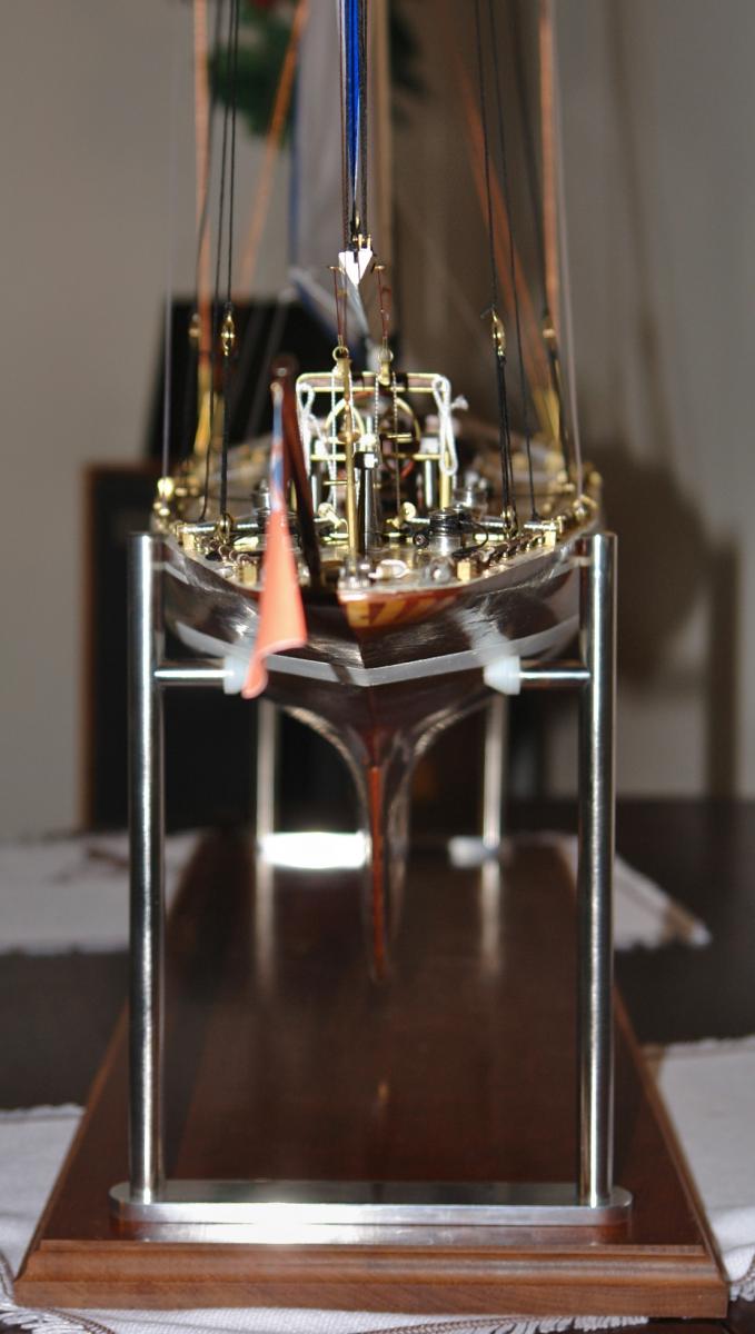
I then assembled the stand and placed Endeavour on it. A bit of levelling and the waterline was horizontal and the yacht had the characteristic rise towards the bow.

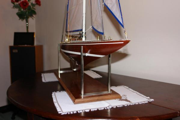
Now all I have to do is disassemble it all and polish up the base.

-
Hi Julie
I hate the thought of painting mahogany as well.
Creating a trapezoid is only necessary where tight curvatures are involved - i.e. the bulb.
I have a piece of oak abut 12 inches long and 1 inch square in which I have machined grooves (miniature circular saw). I have 2 grooves per side each near the edge - 8 grooves in total. The grooves are 1, 2, 3 and 4 mm wide and 1 and 2 mm deep. I sand the planks by placing them in the relevant groove (to support them) and then sanding along their length while holding the sanding block at the correct angle.
The backing will help with the fairing the frames. The laser burn also helps - the fair shouldn't remove all of it as it gives you an indication of when you have gone far enough - i.e a thin line of it remains. Sand along the length of the hull and use a sanding block which spans 4 frames (3 gaps).
A couple of other Endeavour builds featured in NRG do start at the bulb and deck and close at about water line height. The closing pieces are typically thin triangles. Other planks are also tapered to a greater or lesser degree. I wanted nice parallel planks without odd shaped closing pieces. So I started at the deck and worked towards the bulb. This worked well. All this however is relevant to the 2nd planking. You have a bit more flexibility on first planking.
Your guitars are wonderful - very professional.
Keith
-
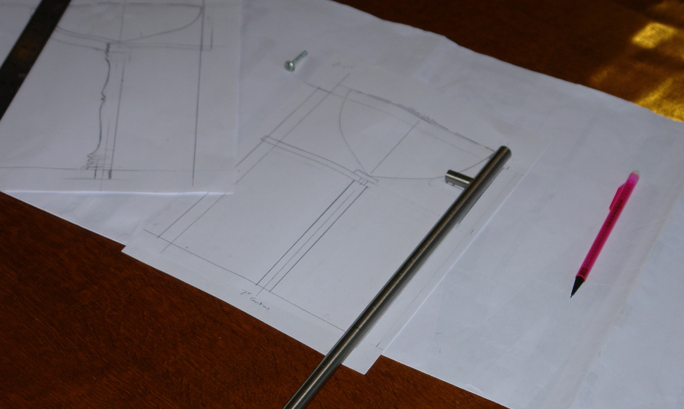
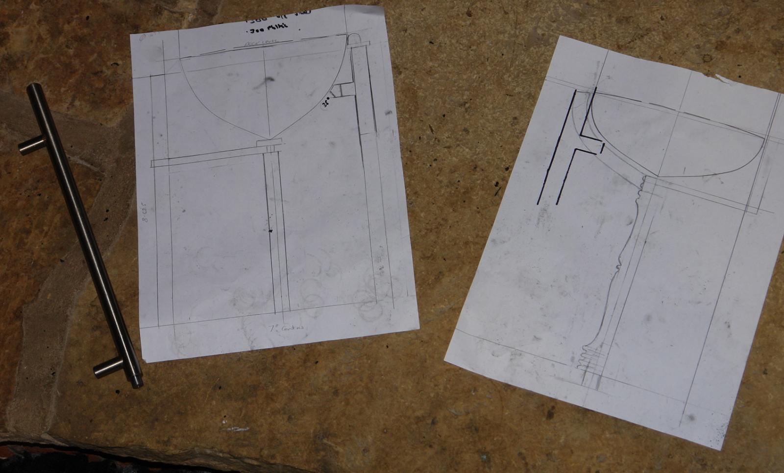
Display Stand
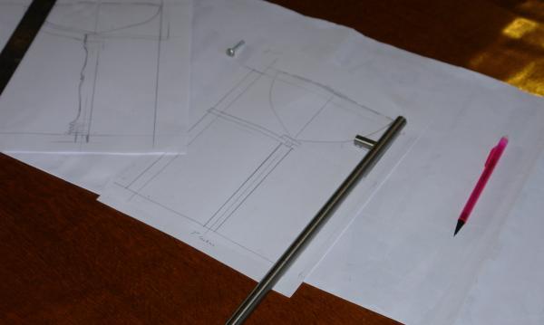
I have now given some thought to the display stand. I don't favour pedestals drilled and screwed into the keel as it always seems wrong to me to drill holes into the bottom of boats - even if they are for static display. This inevitably leaves me with forming some sort of cradle. Cradles can however look heavy and they tend to obscure the lines of the hull. I wanted to fashion something that was elegant and allowed maximum visibility of the yachts beautiful lines. I had a few bits and pieces in the workshop that I felt I might incorporate into the final design as follows:
I had recovered these door handles from a rather expensive kitchen that my wife decided we needed to replace earlier this year. I thought these might come in handy for making the vertical supports.
A few months ago I went to an auction and found a beautiful 1920's 3 leaf mahogany table measuring 6 feet x 3.5 feet. The top and legs were in beautiful condition while the softwood frame had suffered an attack of woodworm. I got it for a song £31 ($50). I thought one of the leaves would provide the base (although I did feel bad about the prospect of cutting it up).
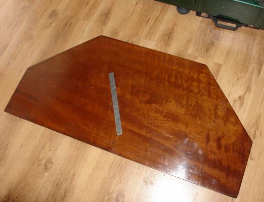
I decided at which frames the cradle would locate and traced the hull outlines at these locations (using the plywood sheet that the frames had been been cut from as a template). I sketched a number of options for the design before choosing one.


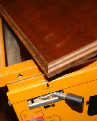
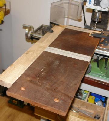
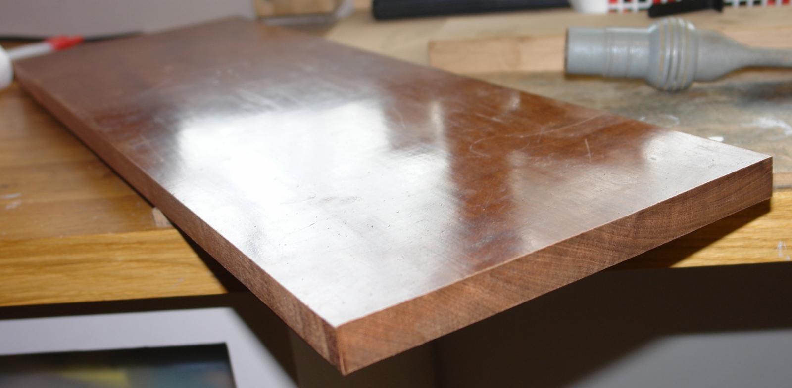
Having decided on the frames where the cradle would fit I measured the critical dimensions and established the overall size of the base. I cut out the base on my saw table and planed the edges on the router table. The mahogany machined up beautifully. You can see from the end grain that the mahogany is a single piece (indeed the whole table leaf was made from a single piece of timber 2 foot wide. Working with mahogany nearly 100 years old is a wonderful experience.
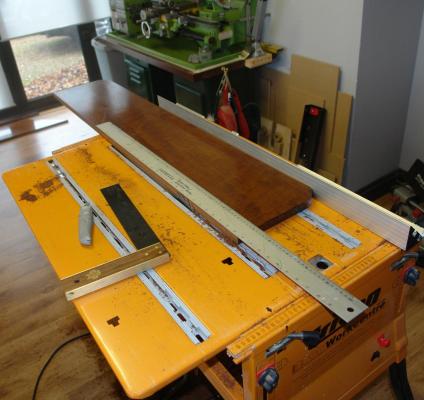

Having cut out the base, holes were drilled and counterbored to take the bolts for attaching the cradle supports.
I will cover the rest of the stand build in the next post.
- michael mott, dgbot, GuntherMT and 4 others
-
7
-
Hi Julie
A few comments here.
The 2mm x 2mm planks can be held in place quite well using elastic bands. I found they needed to be sanded into a trapezoid to butt up snugly. Your interpretation of the instructions for planking the bulb are correct. You don't need to cut the elastic bands, stick a pin or nail in the frame near the plank, loop the band over it and then wrap it round the planks. Finish by hooking the free end over the same nail.
As you suggest if you are planning to use the plywood drop keel you will have to be careful not to get glue on it. You could try covering it with Sellotape, to be remove once the gluing is complete.
If you are not backing the planks (as I did) you need to take great care to make sure the edges of the planks align. Any misalignment will have to be taken out by sanding or filling with wood filler. Sanding often leads to holes or at best a tissue thin shell if alignment isn't near perfect. Wood filler is often used by builders - particularly on 1st planking.
The reference to vinylic I think refers to PVA wood glue. I used Evo-stik PVA wood glue.
There are a number of ways of approaching planking a hull. Many builders seem to favour starting at the bulb and deck and working towards the middle (waterline). I found this hull planked relatively well working from the deck to the bulb.
Keith
-
-
-
Hi Julie
Once you get on to assembling the frames make sure that the assembled frames are "true". On mine their was a slight bow and a pronounced twist from bow to stern. Eyeballing the assembly by looking along the frames from the bow with your eye just above the deck level should reveal any distortion. The kit instructions suggest you temporarily nail the deck in place to control distortion during gluing. This might address the bowing but it does not provide sufficient rigidity to cure twist. You may recall that I found it necessary to bolt an oak plank to the deck to hold it true.
Did you resolve what you are going to do about jointing the mast?
I bought From "Enterprise to Endeavour" by Ian Dear to accompany my build. You might find it interesting.
Regards Keith.
-
Hi Julie
Its a bit late here so this may be a little brief.
My concern about the dinghy is that with only the bow and transom secured the planks will have a tendency to spring back to their former flat shape when removed from the frames. I had thought of trying to get a mid section frame in place to prevent this. I thought clinker might be better as the overlapping of the planks would give extra stiffness. I shaped the frames with a small sanding block. It took an hour or so. I think nailing is a bit optimistic as my guess is that the ends of the planks will split. I would be inclined to rely on glue but if you do nail I think pre drilling will be necessary.
In my kit the dowels were half rounds and the mast dowels were staggered so the end joint was only ever half of the mast thickness. I had 5 half rounds from which to form the mast (2 half lengths and one full length on one side and 2 full lengths on the other) I found the segmented mast had the benefit of allowing me to get it very straight. I did hunt for a dowel long enough to avoid jointing but the ones I found all had an unacceptable degree of bend. You refer to 3 dowels - is your kit different to mine? I agree end jointing of 3 dowels would be useless.
The romance of your dock vision is compelling. Can you build a bar on it please?
I often sit on deck after a long day at sea (usually in the rain if its Scotland) sorting through the rats nest of lines that my fellow crew members have abandoned in favour of their gin and tonics. I get a bit OCD (obsessive compulsive disorder) about rats nests. The practical point however is that lines dropped on a deck tend to collapse relatively flat to the deck as their weight overcomes the stiffness in the line. At model scale the opposite is true and the stiffness overcomes the weight. The result is that they stick up at odd angles and don't look very realistic. You might want to experiment before deciding which way to go.
Goodnight
Keith
-
-
Hello Julie,
I didn't build the dinghy because the refurbished yacht relies on an inflatable. I did assemble and sand the frame and I and may get round to making it one day. I think it might be quite tricky as its planked without attaching the planks to the frame - so that it can be removed. Usually dinghys of this type are clinker rather than carvel built and I don't recollect this being covered in the instructions.
As to handling the Yacht I think you will find it very easy until you attach the mast. This can be towards the end of the build and you should be able to get on without worrying about transport until the mast is attached. In my build I did make the mast removable - all the shrouds and stays attach to the deck with bolts and all the sheets etc, are tied to the deck fittings. I didn't explain this in the build, perhaps I should have done. You can see the attachment details in some of the photographs.
One thing you might like to consider before starting is how you want to display the model. I quite like having the model sat in a cradle once complete. If you go down this route you can get on with the build and worry about the cradle later (or alternatively use the one provided). Many builders however favour screwing dowels (metal or wood) into the keel. If you go down this route you will need to attach some form of captive nut arrangement into the frame.
By the way - very nice workshop. I would have gone into mourning If I'd had to leave it.
Keith.
-
Hi Julie,
Very pleased that it finally arrived. I look forward to following your progress.
I know 3 rules of workbenches / tables as follows.
Rule 1 - The size of the workbench is inversely proportional to the tidiness of the owner.
Rule 2 - The bigger the workbench the more time spent looking for the tool needed.
Rule 3 - Workbenches larger than needed are ideal places to park tools which are not needed.
Keith.
-
-
Hi
I find soaking wood in container of boiling water is the most convenient method. For anything up to 1/8 inch a few minutes soak will do the job. You can vary the size of the container to match the piece of wood you want to bend and any water left in the kettle can be used for coffee (or tea in my case). When bending long strips I use a steam wallpaper stripper and push the strips down the steam outlet tube.
Keith


Endeavour 1934 by Julie Mo - Amati - Scale 1:35 - America's Cup UK J-Class Challenger
in - Kit build logs for subjects built from 1901 - Present Day
Posted · Edited by KeithAug
Hi Julie
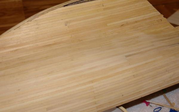
This photo (borrowed from another members build) gives some idea of the problems encountered without backing. If you consider the sanding needed to get this smooth you will appreciate the degree of plank thinning that is involved.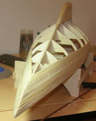
By way of contrast look at this on my build with backing.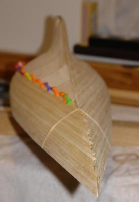
Zooming in to both photographs shows the issue better.
Regards Keith