


KeithAug
-
Posts
3,267 -
Joined
-
Last visited
Content Type
Profiles
Forums
Gallery
Events
Posts posted by KeithAug
-
-
Hi Nick
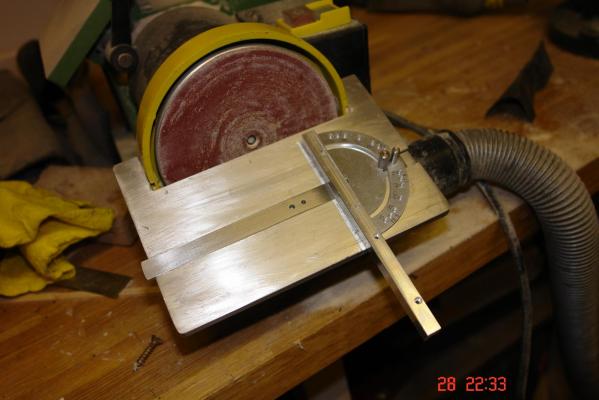
Here is another cheaper option.
I bought this from Warco although other suppliers sell the same machine:-

BDS 130 Belt & Disc Sander
It costs £69. If you don't want the belt a cheaper version without it is available. The belt does make it quite noisy.
The mitre gauge / table was very rough and ready and not very accurate so I machined up the surface and widened the slot to take the mitre gauge off my Byrnes table saw. The result is a perfectly adequate and accurate disc sander.
Here is my sander as modified.

-
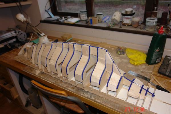
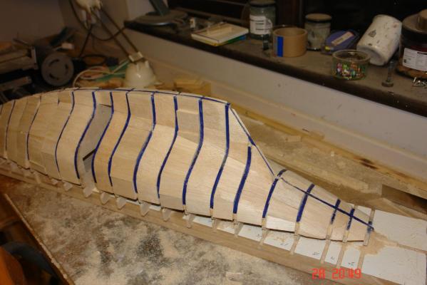
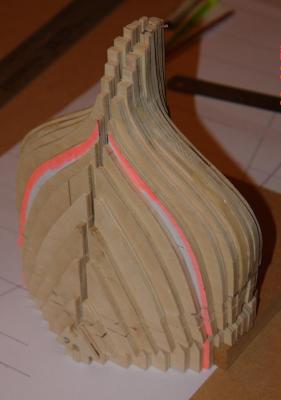
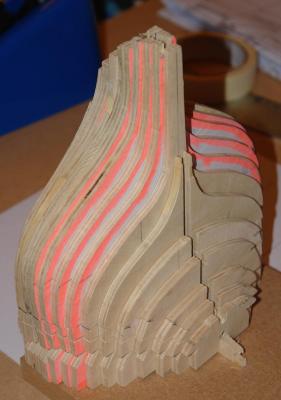
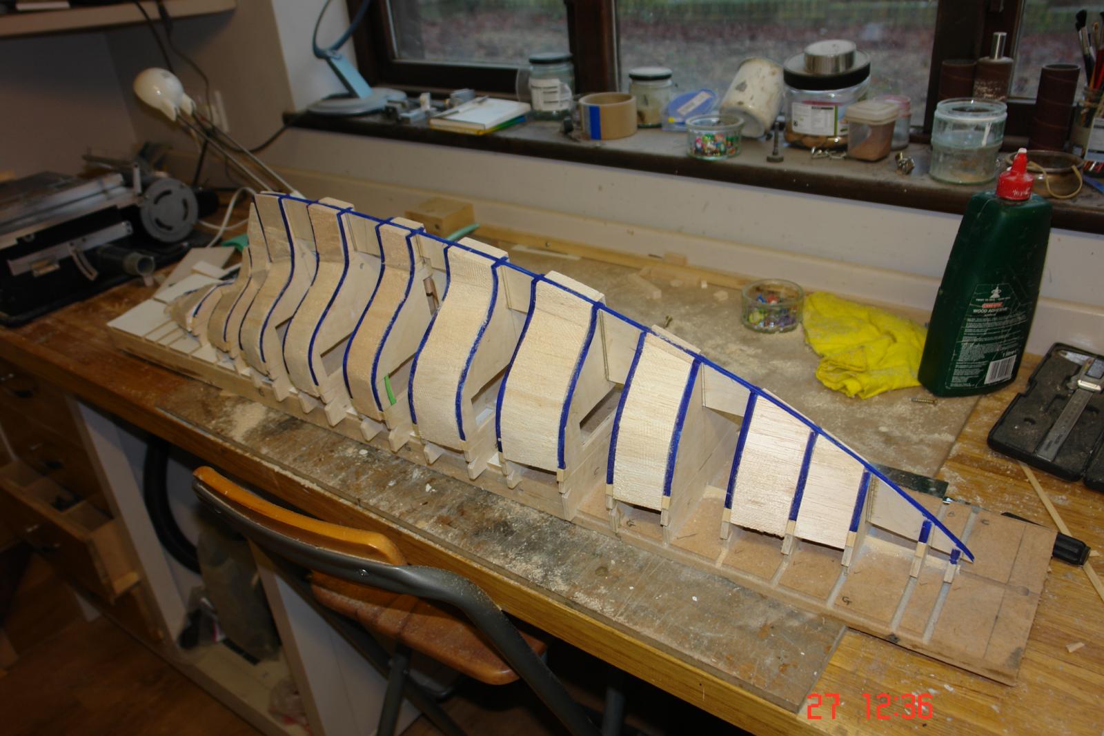
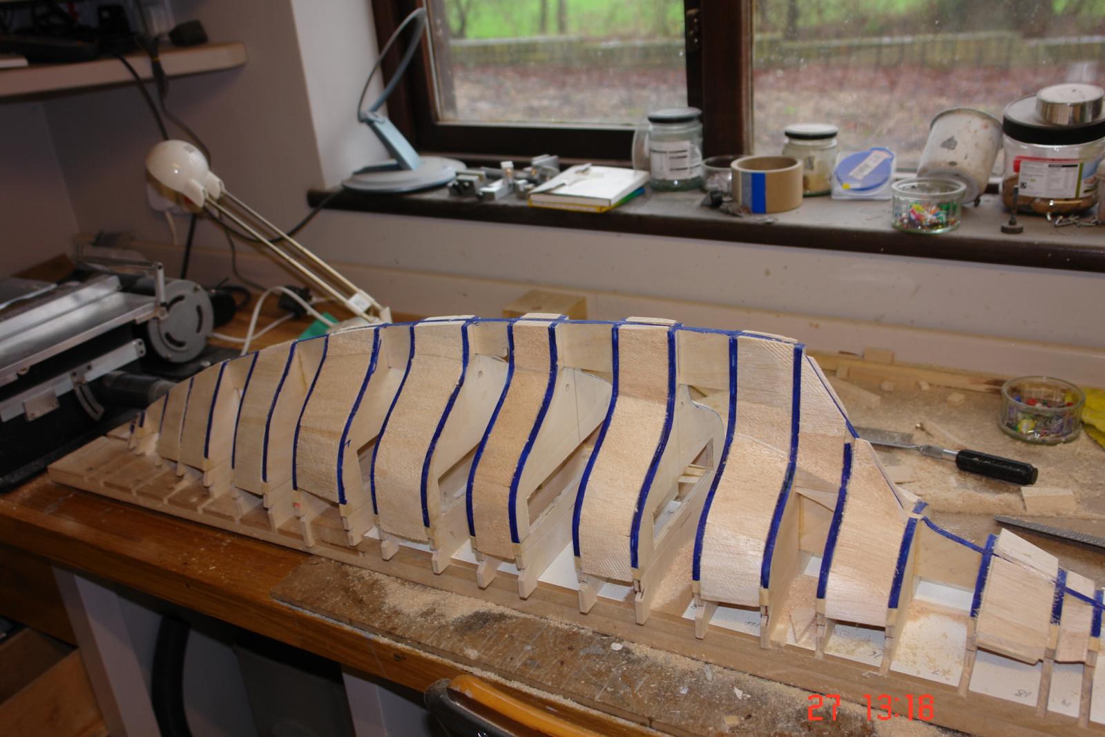
Balsa Infill Prior to Planking
I find infilling between frames with balsa eases the planking operation. Also I quite enjoy the process as it’s a bit of a challenge creating the 3 dimensional shapes necessary to nest between frames while conforming to the profile of adjacent infill pieces. All the balsa is ½ inch plank 3 inches wide by 18 inches long. I needed 12 planks to complete the hull – cost me £12 on ebay.
I use a disc sander for shaping – mine has been modified to take the miter gauge from my Byrnes saw. A simple and cheap way of getting an acceptably accurate disc sander.
Having completed the rough fairing of the frames I re-marked the edges of the frames with the felt tip pen. This would give me the guide for final sanding once the balsa infill was complete.
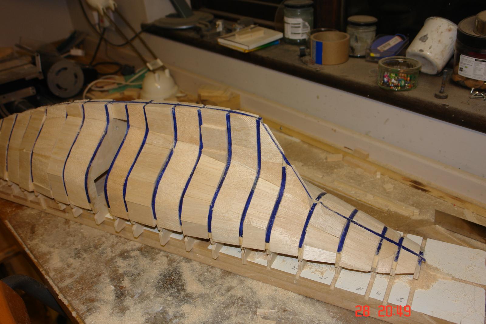
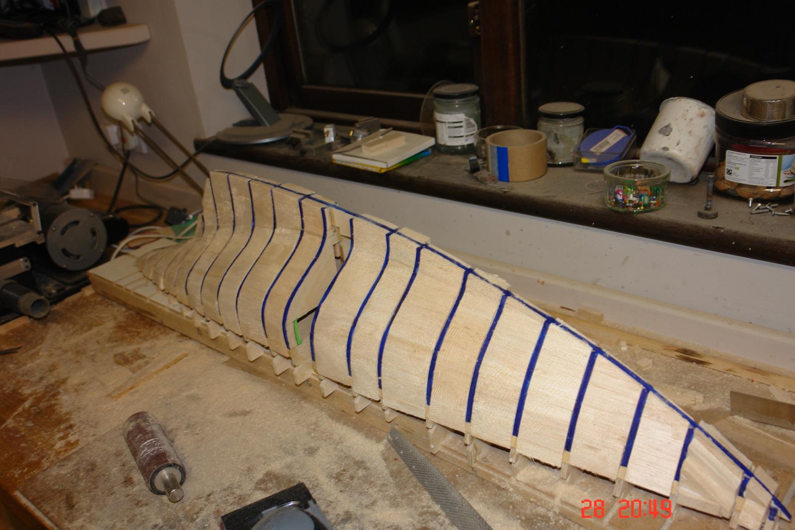
I find filling alternate frame gaps with balsa has the benefit of allowing me to progress while the previously completed and glued balsa infill dries (I use a PVA wood glue). Also at this stage I roughly shape the infill using a rasp leaving about 1/16 inch of balsa proud of the adjacent frames – for final finishing with sandpaper.
I then infill the remaining frame gaps before finishing the rough shaping with the rasp.


- JerryGreening, PeteB, gieb8688 and 12 others
-
 15
15
-
Michael / John
The lines are looking good - nice rounded form, not a sleek racer but nice never the less. I need to think about what's next. I filled between the frames with balsa on my last model and then double planked and it worked so well I think I might repeat it again although I may just single plank. Decisions decisions!!
Keith
- mtaylor, Nirvana and aviaamator
-
3
-
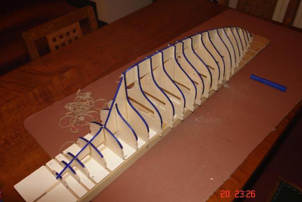
Frame Adjustment & Fairing
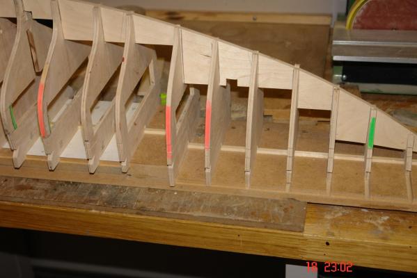
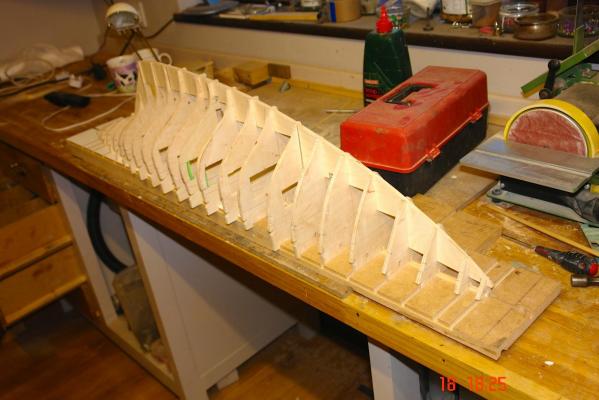
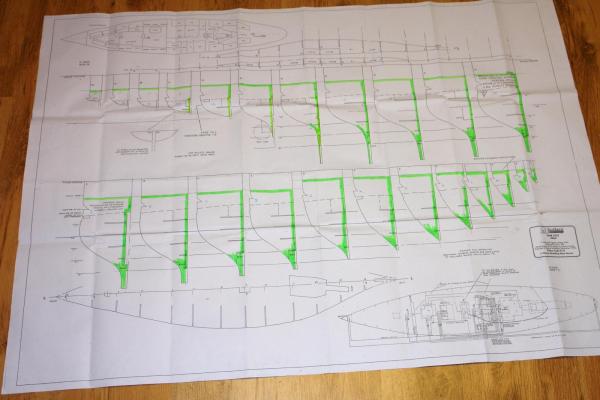
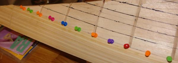
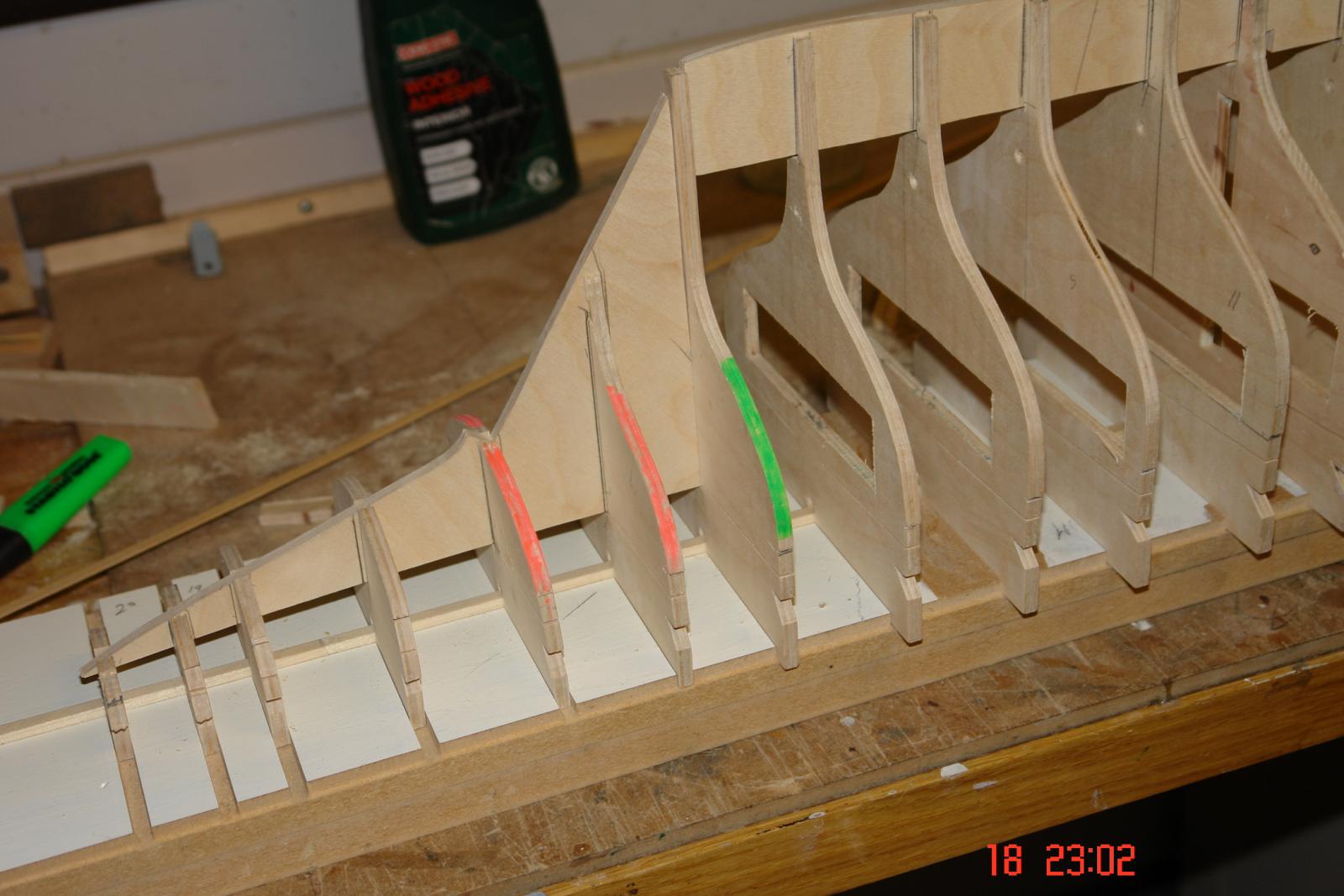
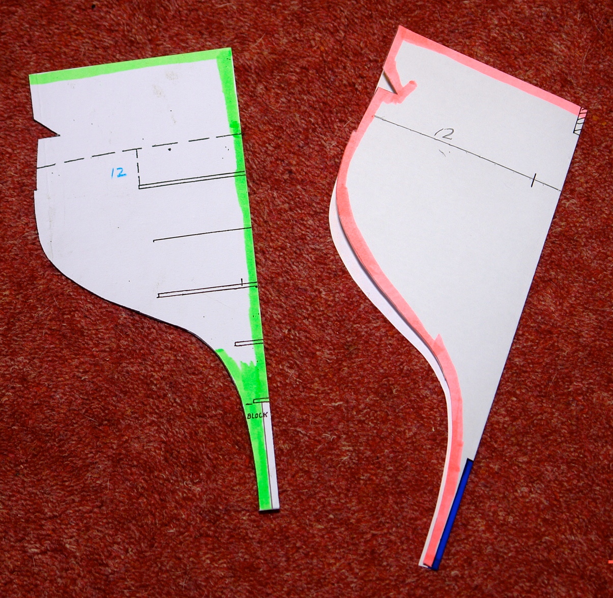
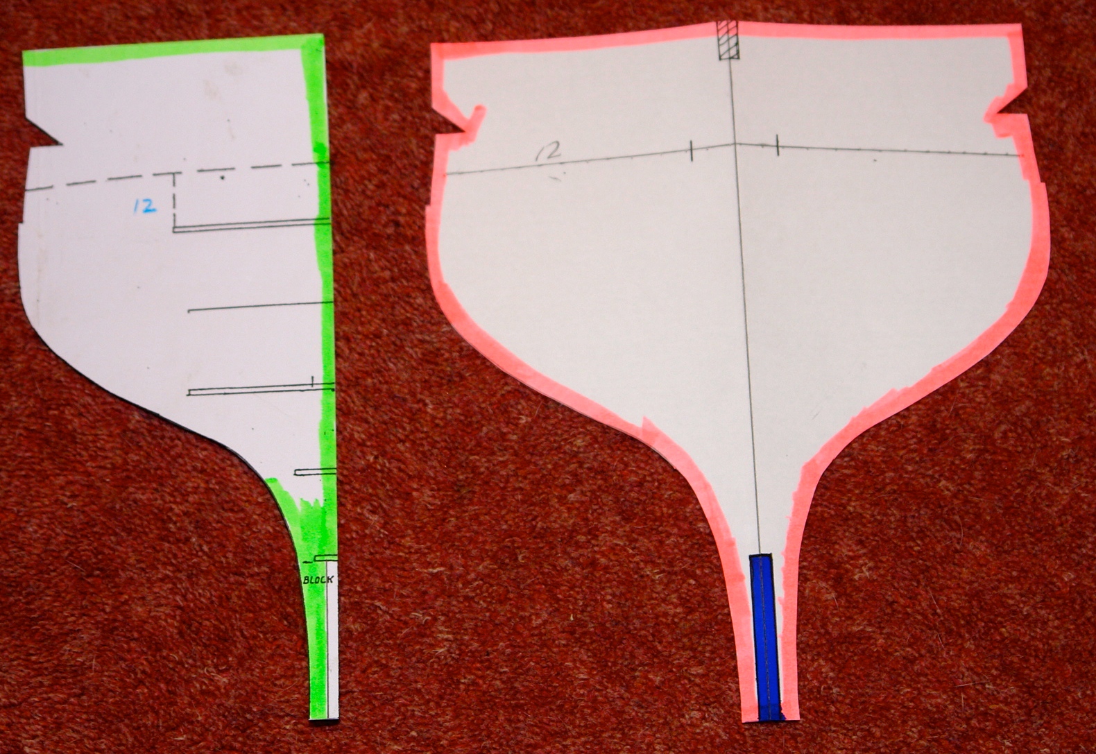
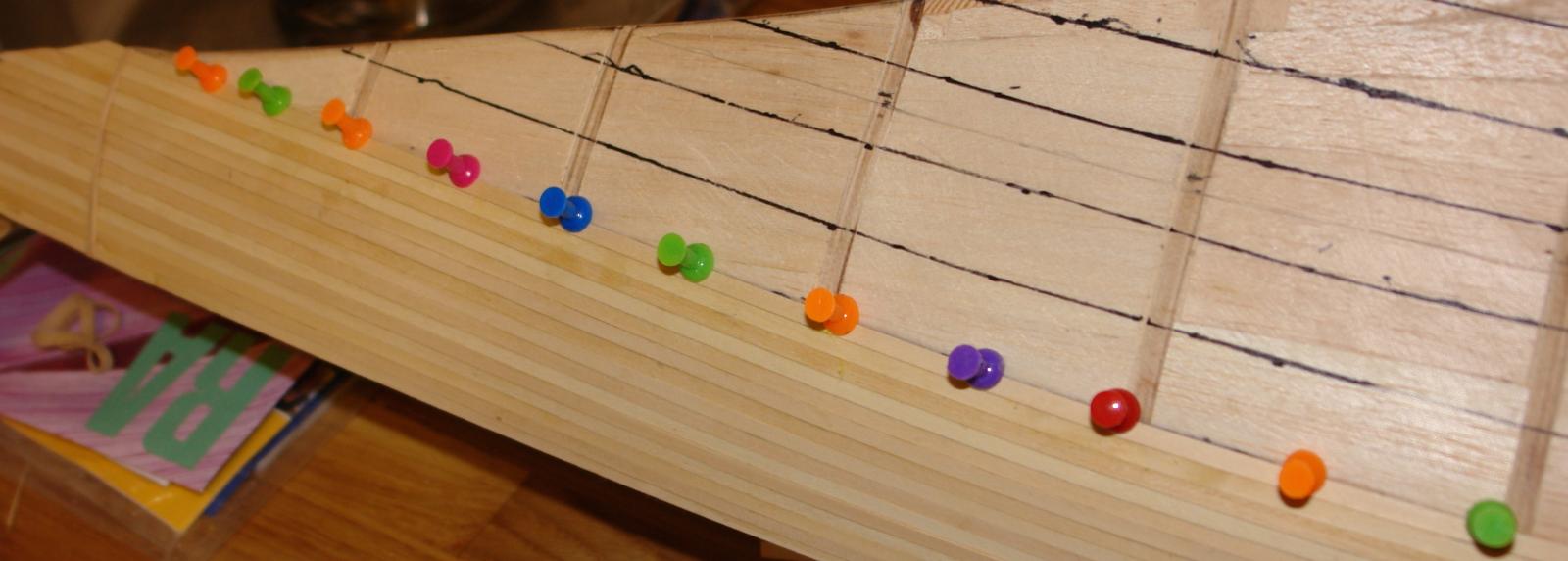
Having done the test assembly I did the usual plank check by laying a .040” by .200” plank along the length of the hull and looking for high and low spots. The significantly oversized frames were marked with a green felt tip and the significantly undersized frames were marked in pink. By significant I mean a deviation of between .040 and .080 inches. See Photos.

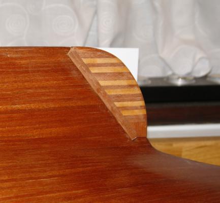
The oversized frames were easily adjusted using disc sander while the undersized frames had to be built up by bending and gluing .040 strips of wood around the frame edges.
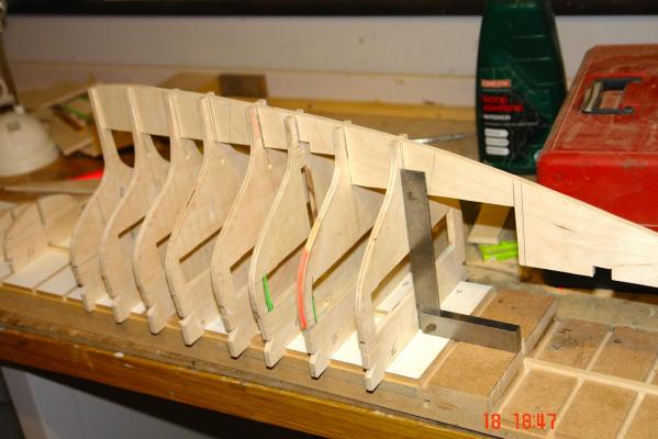
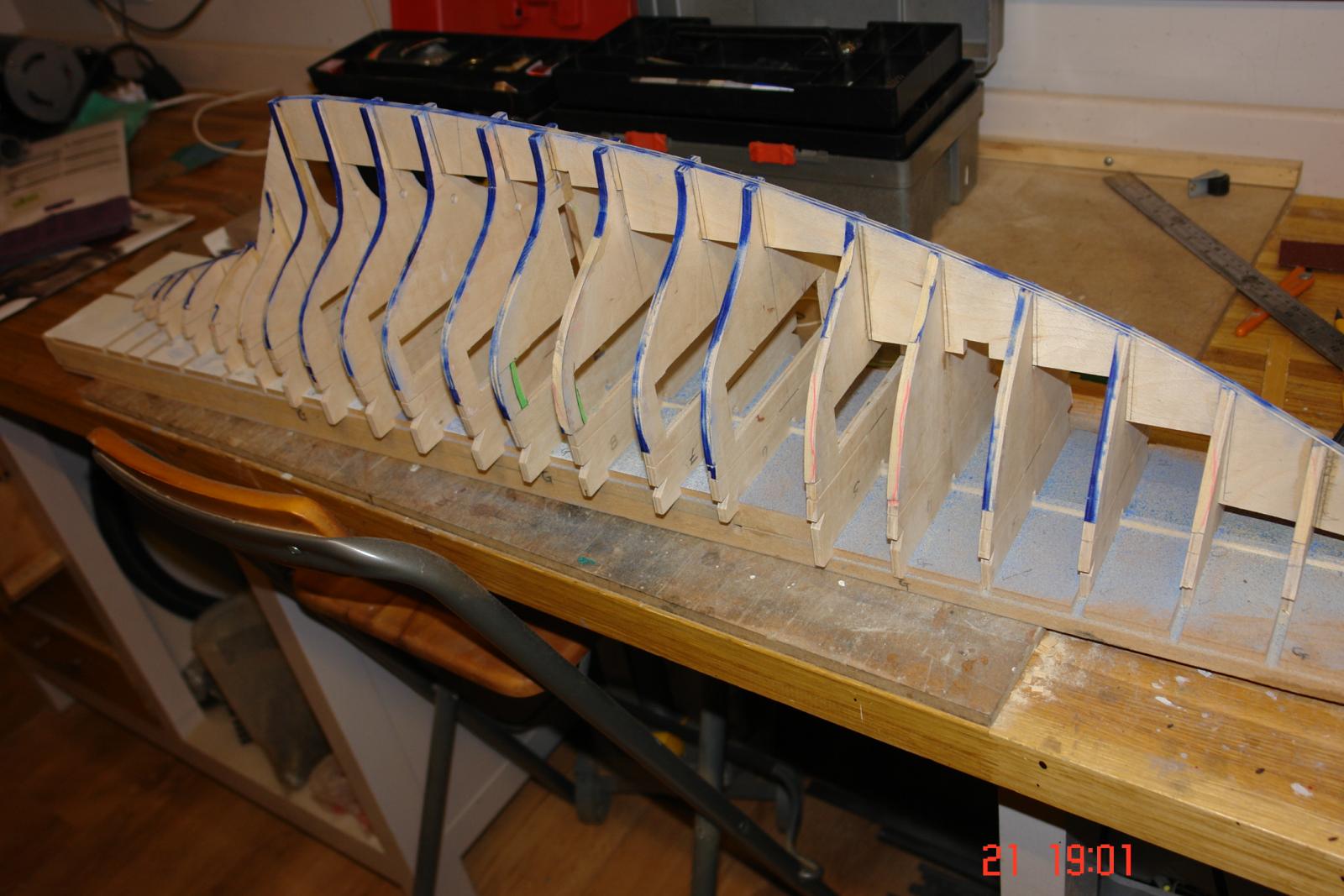
Having got the frames about right I then glued up the skeleton of the yacht. Only 4 of the frames were glued to the building board to ease removal at a later date. Because all frames were positively located in building board the gluing of 4 frames proved sufficient to create a very rigid assembly.
After gluing I used a felt tip pen to colour the edges of all the frames. I do this as I find it gives a very good guide when sanding to fair the frames. By watching where the felt pen is removed during sanding I am able to duplicated the fairing on both sides of the hull and ensure that that the blending of the hull lines is uniform. I take my time while sanding and frequently check the form of the hull using the previously mentioned flexible plank. See photos.

-
-
Keel and building board
A bit more progress fitted in around various DIY jobs. I transferred the keel shape to card that I the stuck to the ¼ inch ply before more jigsaw work. See Photos.
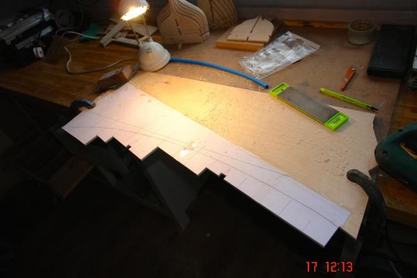
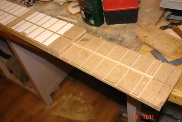
I made the building board from ¾ inch thick 6 inch wide MDF. For about 2/3 of the length of the hull the building board is double thickness with the stand off for the frames reduced in height to compensate (reducing plywood wastage). Using my router table I machined slots along the length of the MDF to facilitate:-
1. accurate alignment of the 2 boards
2. location of the frames along the center line
3. location of the board on the milling machine to cut slots for the frames at right angles to the center line.
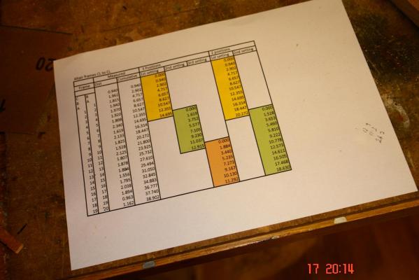
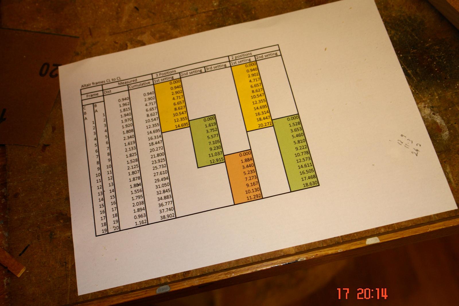
The frame spacing was accurately measured from the plan and I used the digital read out on the mill to accurately set the positions for the frame sots. None of the frames were equally spaced which was a bit of a bind.
The photos should illustrate the process.
Finally I did a test assembly of the frames to give myself a feeling of progress.
Everything fitting together well and all right angles accurately made .......... feeling very content!
-
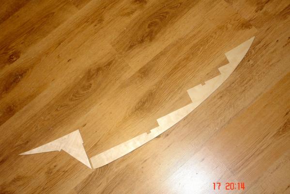
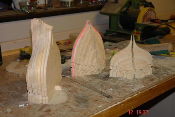
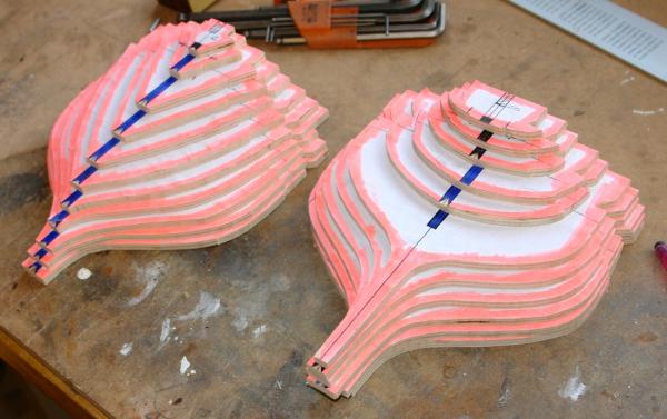
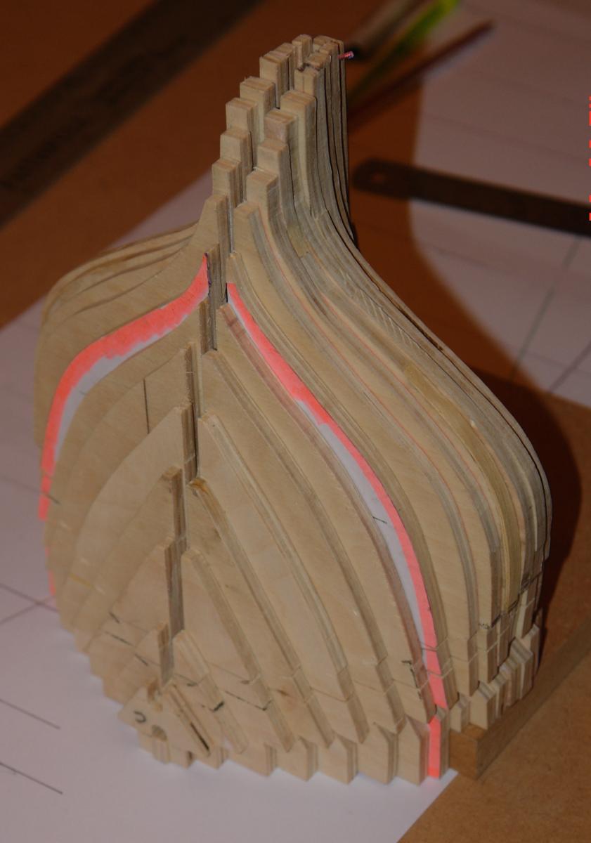
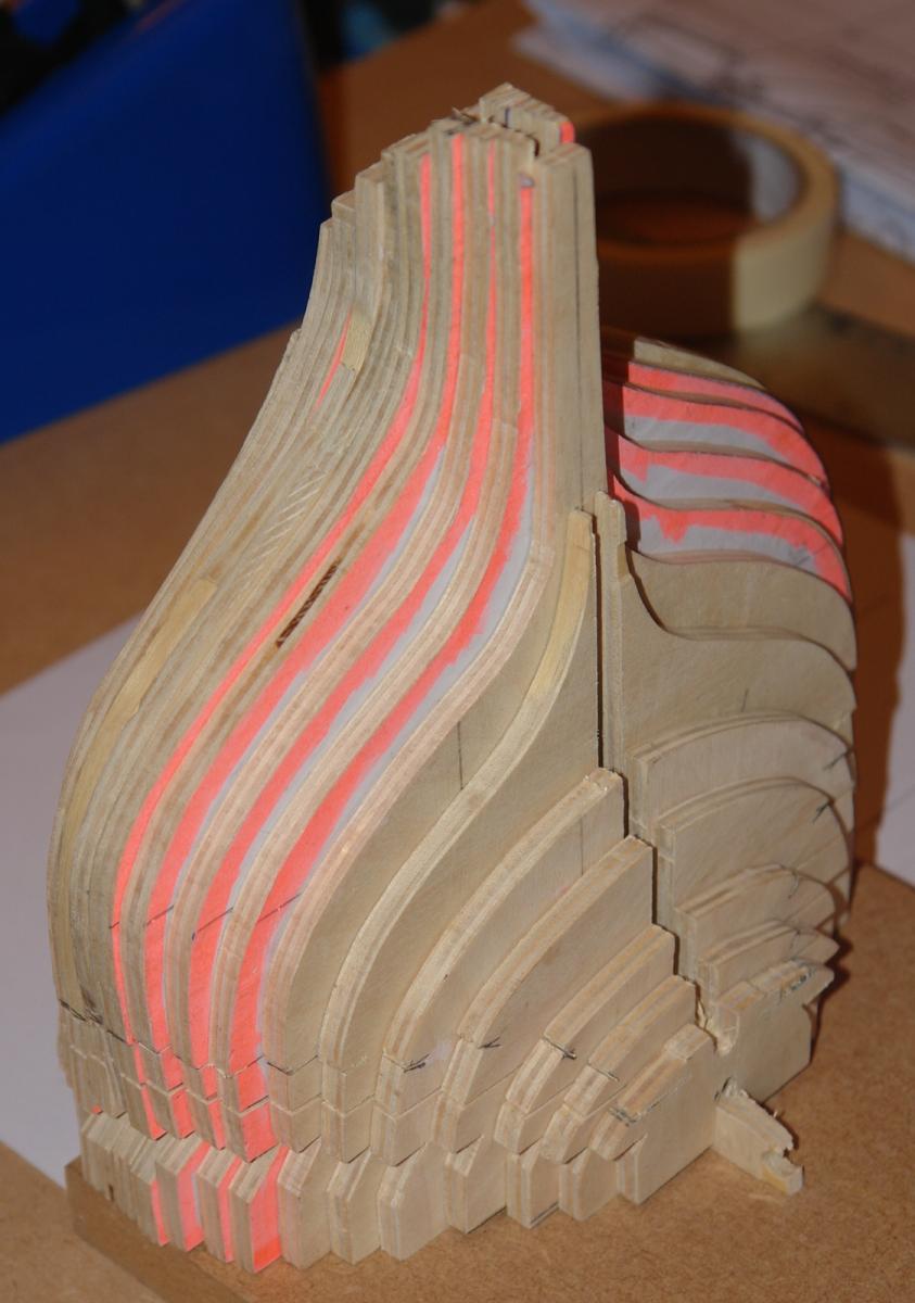
Frames finished (23 in all)
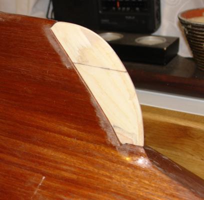
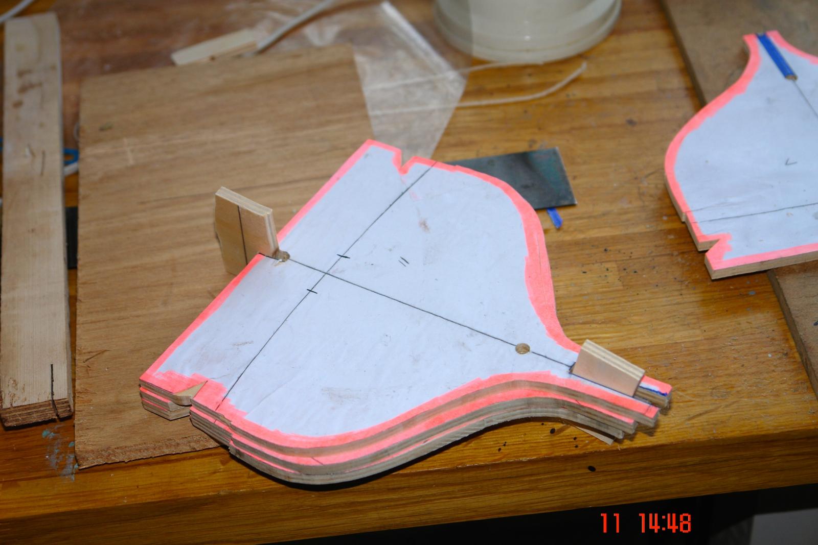
Having cut out the frames I stacked them and did an eyeball check on how well they nested. All seemed to be sensible with the exception of frame 8 which was noticeably too narrow by about 3/16 of an inch. I assumed that I had marked it out incorrectly so rechecked it against the plans. It turned out that I had marked it out correctly and the frame drawn on the plan was incorrect. The frames on the plan are all individually drawn rather than the normal convention of overlaying all hull lines on a single image. The latter approach would of course have revealed the error during the draughting of the plans. I corrected the problem by widening frame 8 with strips of wood on either edge and then sanded by eye using frames 7 and 9 as guides. See Photo.

I used the jigsaw to cut through about 80% of each frame at deck level to ease removal of the building board up-stand later in the build.
I then stacked all frames to satisfy myself that the transitions between frames seemed logical.
- PeteB, Pierretessier, Omega1234 and 16 others
-
19
-
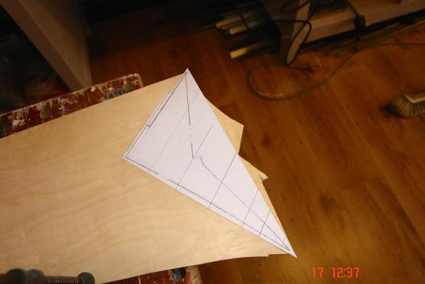
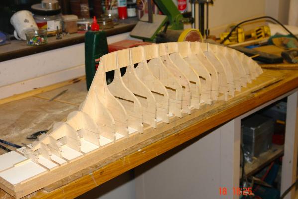
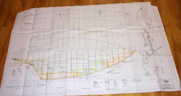
A dilemma for the future?
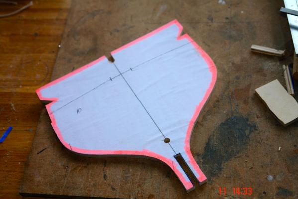
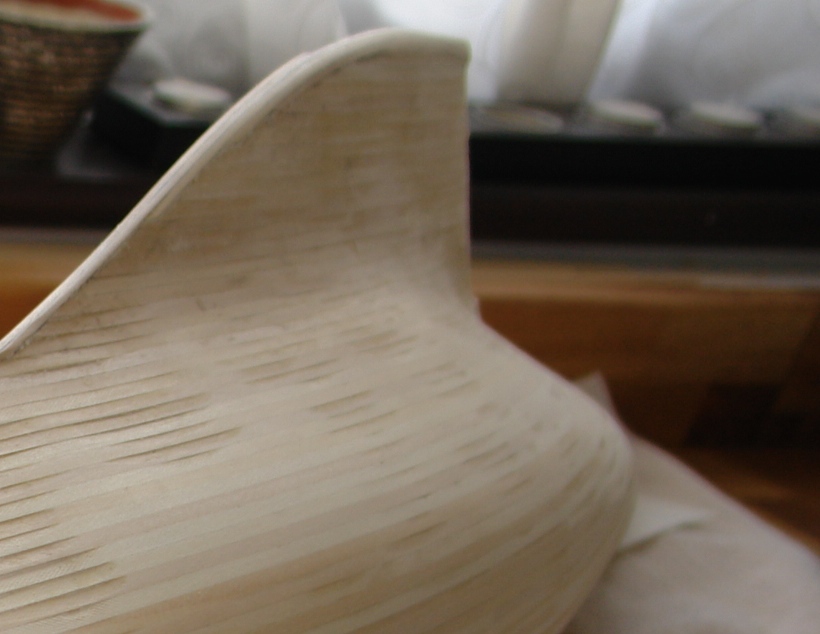
Bulwarks extend above deck on all sides. So the dilemma is do I do the deck and deck planking before the hull planking. The advantage of this sequence is that I get unrestricted access for fitting the sub deck and sanding the deck planks. The building notes suggest hull planking first!!! All this is made a bit more complicated by the sculpturing of the upper section of the hull. See Photo.
Hello Michael - my jigsaw work is flattered by my camera, its ok but not as good as I would like. I really need to bite the bullet and buy a scroll saw. However I have so many saws and I'm worried that my wife will think I am developing a saw fetish.

- tasmanian, pete48, michael mott and 7 others
-
10
-
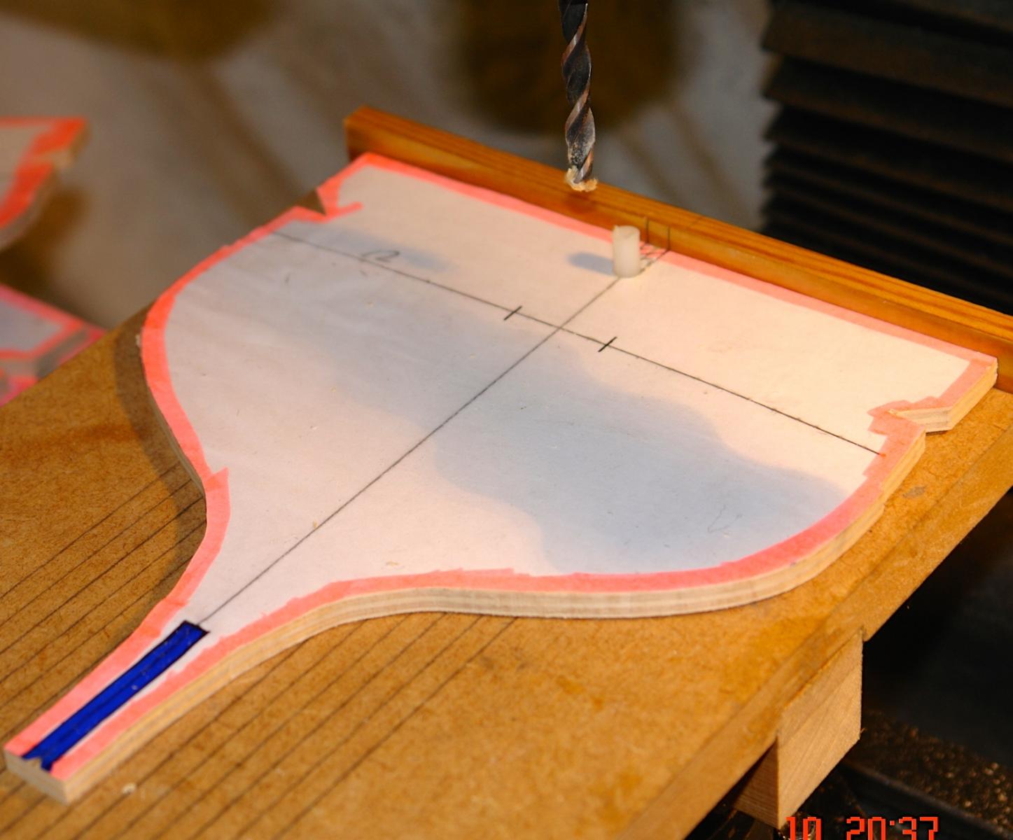
Keel and building board location slots.
The important thing here is that the keel and building board slots are accurately cut to width and that they are in perfect alignment with one another. I did consider cutting them freehand but decided to try and find a way of slotting them out accurately on the mill. The slots needed to be ¼ inch wide to match the ply that I intended using for the keel.
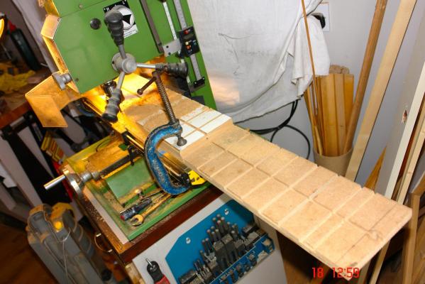
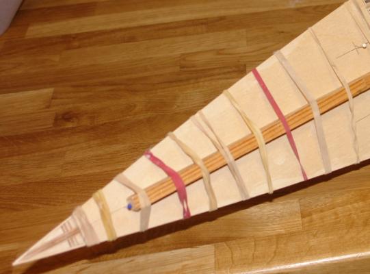
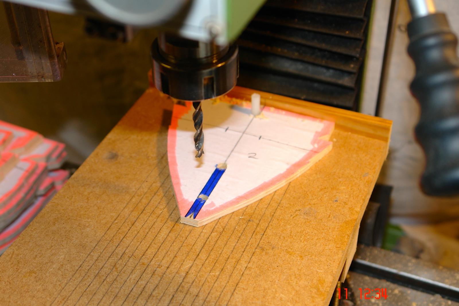
I started by making a jig for drilling - see photo. With this I drilled holes at the inner end of the location slot in all the frames. By drilling trough the frames and the jig I created a position for a location peg (1/4 inch diameter) which meant I could accurately reposition the frames to drill the ¼ inch holes at the end and at interim positions in the keel slot.
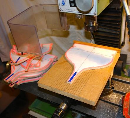
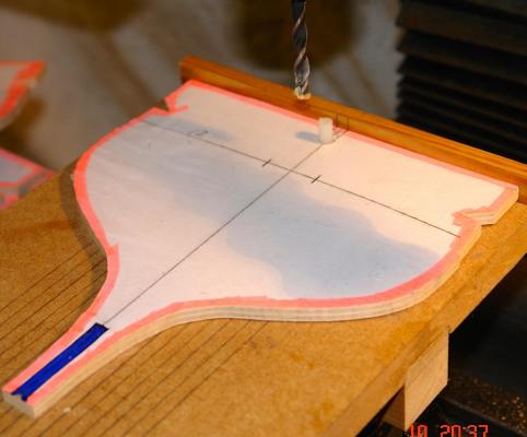
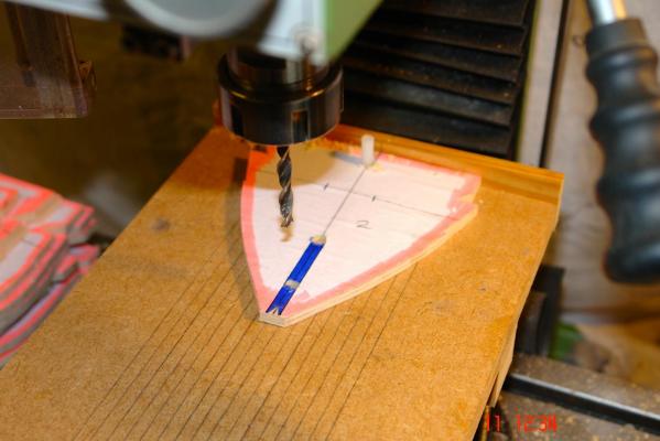
I should explain that I am drilling using a mill with an x/y table. I am keeping the y setting locked and only varying the x setting to accommodate the different positions of the keel slot. I am therefor ensuring that all the drilled holes are in alignment and at right angles to the building board edge of the frame.
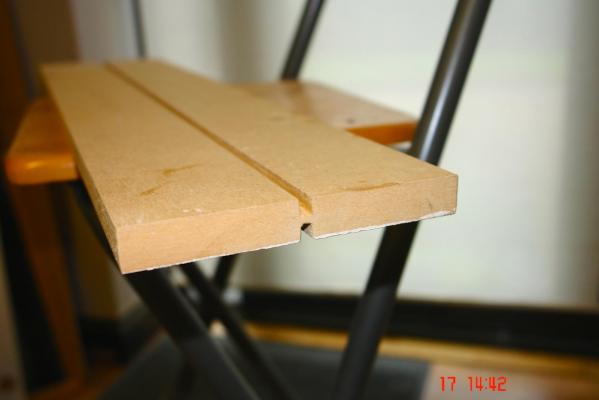
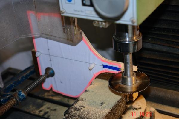
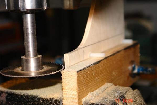
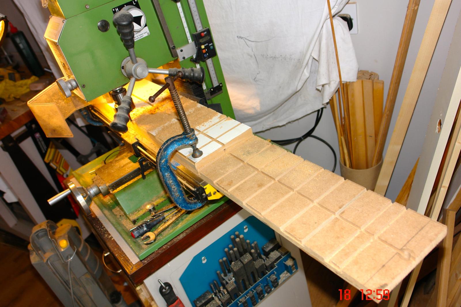
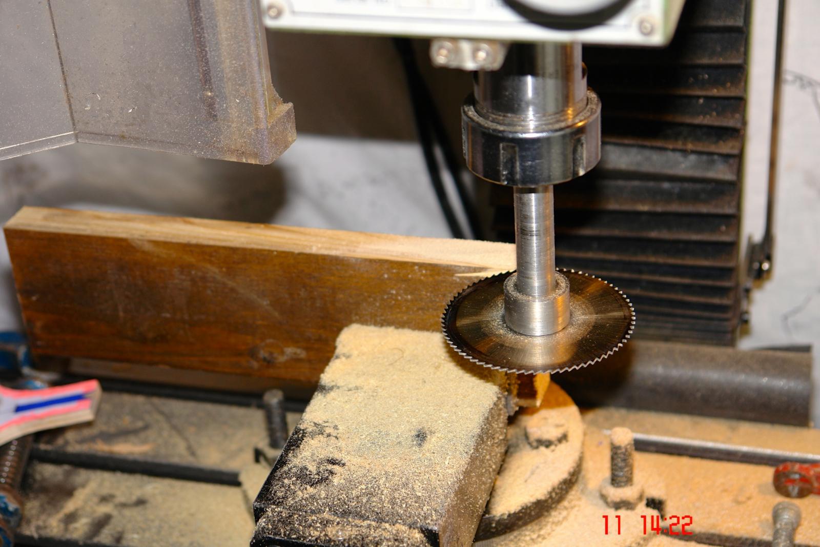
To cut the slots accurately I decided to use a slitting saw mounted in the mill. My first operation was to mount a piece of wood vertically in the mill vice. I then locked the mill spindle and machined off the upper edge of the wood using the slitting saw, thus ensuring that the saw cut relative to the wood was the same for all subsequent cuts. See Photo.

Using the ¼ inch holes in the frames with a pair of location pegs I then clamped the frames to the wood with the pegs tight against previously cut surface. Once clamped the pegs were removed. With the slitting saw (still locked in its preset vertical position) I then cut one side of the keel and location slots (obviously two cuts from opposite ends). See Photo. I then unclamped the frame reinserted the dowel pegs flipped it over re-clamped and repeated the cuts as before. Result! – accurate ¼ inch keel and location slots perfectly aligned.

-
-
-
ALTAIR is an auxiliary gaff rigged schooner built by William Fife & Sons at Fairlie as yard number 789. She was launched in May 1931.

The 1.32 scale model plans were created by Sandy Cousins and produce a model 1200mm LOA and 200mm Beam. The plans are on 6 sheets and include building notes by the author.
The plans can be used to create a sailing model. To achieve this requires the addition of a significant extension to the keel in the form of a metal plate some 100mm deep with a swing keel pivoting below this. As I am building a static display model I don’t need to worry about this.
So to begin………..
I chose this build as as I had really enjoyed building the Amati Endeavour 1:35 kit but wanted to return to scratch building for my next project. My daughter bought me the plans and they were delivered by Santa a couple of weeks ago.
As designed the plans suggest that the main frames are made from 1/8 inch ply stiffened by several 1/8 inch ply “decks” forming a box structure. This felt overly complex and I resolved to make the frames out of ¼ inch ply as I had done on previous models with a ¼ inch ply keel running the length of the model. The plans also suggest that he hull is constructed attached to a building board. The allowance for the upstand from the board seemed excessive and potentially wasteful so I reduced it by about 1 inch at the bow and about 1.75 inch at the stern. I will step the building board to allow all frames to sit correctly relative to one another.
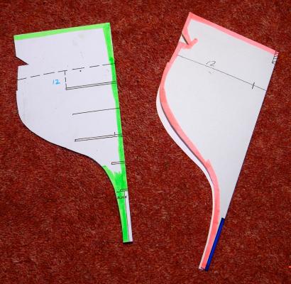
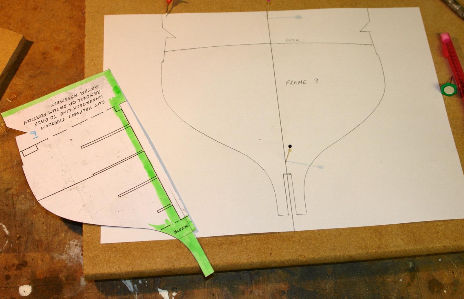
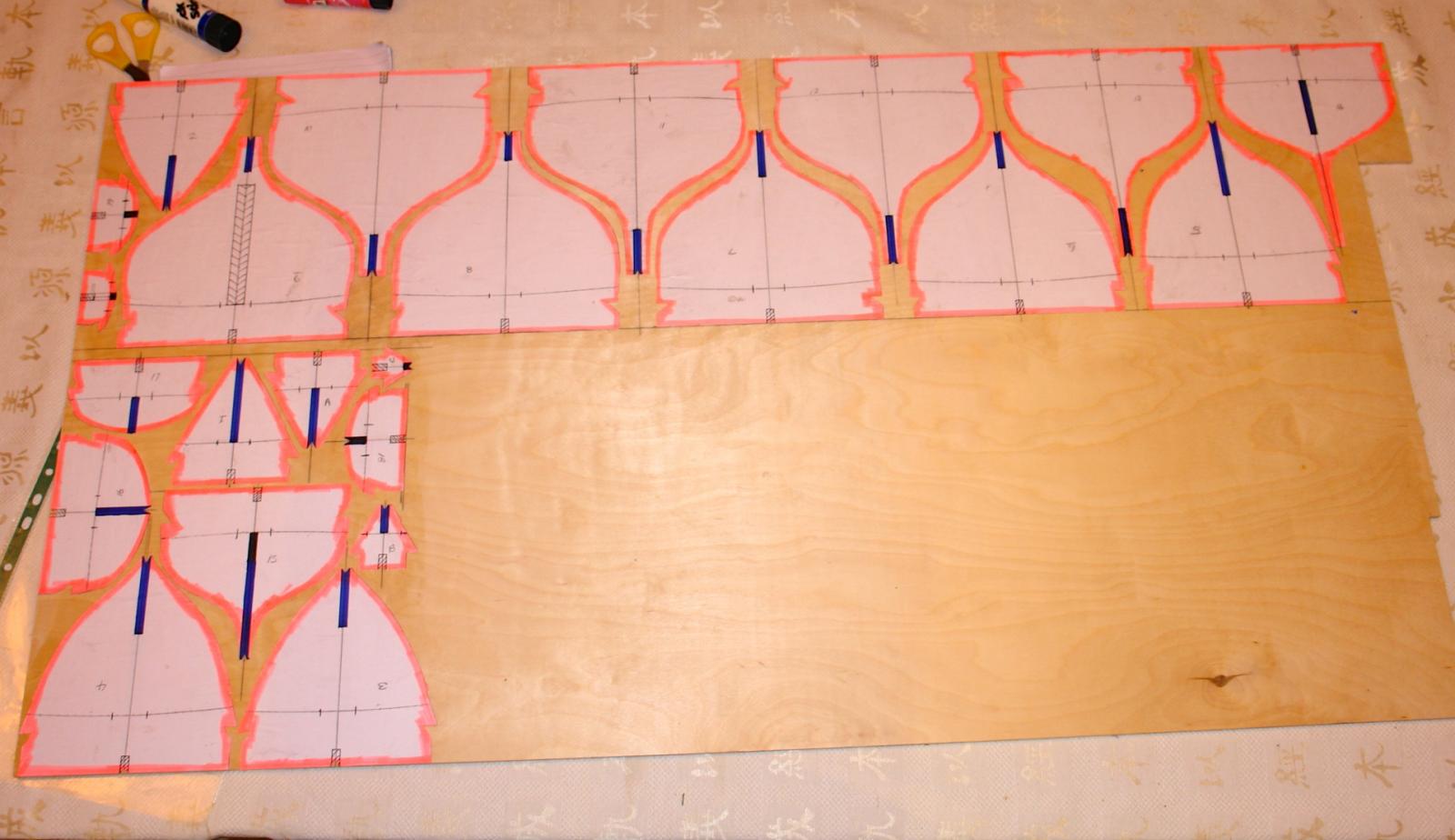
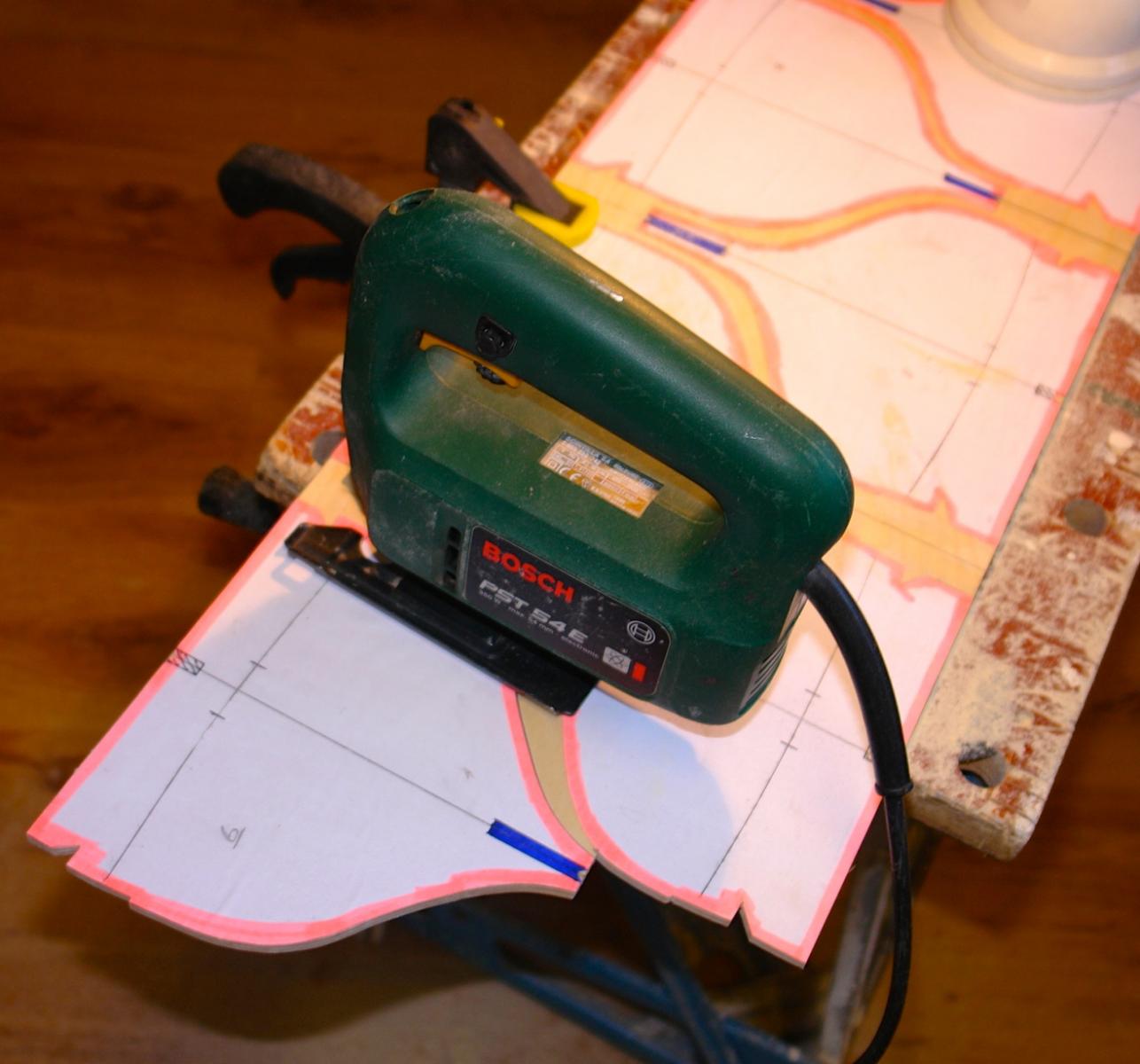
I considered a number of options for marking out the frames. As per normal practice only half frames were drawn. The building notes suggest transferring the outlines to the ply using carbon paper. I didn’t fancy this and decided to cut out the frame outlines from the plan and then mount the half frames on card to create templates. The templates were then used to transfer the outlines onto folded paper. Once cut out and unfolded I had the frame cutting profiles and these were attached to the ¼ inch ply with Pritt Stick glue. I tried a few arrangements to get the minimum waste. Before cutting out the frames using a jig saw with a fine cut blade. I don’t have a scroll saw and cant justify one for the limited use I would make of it. After a number of hours of careful cutting I finished up with a reasonable set of frames.


I have left the frame keel slot and the building board locating slot uncut while I decide how to saw these accurately as this will be key to a successful build.
Well thats enough for now - back to more sawing tomorrow.
Keith
-
Hi Julie
One of the benefits of backing that I didn't mention is that mistakes are buried under the following layers. One of the things I most like about model boat building is that its new every time. No two boats are alike and in consequence each one throws up new challenges. Overcoming the challenges and correcting mistakes is a key part of the fun and satisfaction.
I did wonder about the rasps - I have never used them and in fact don't own one. I tend to use coarse oxide paper (60 grit) on a sanding block for roughing out - followed by progressively finer grades for finishing. However inspired by you experience I have just ordered a set of rasps.
Keith
-
Julie
Re clinker effect.
If you try to bow a plank in 2 directions at once (i.e bow in the weak and strong direction) the wood tries to deal with the stress by twisting. This causes one corner to press in to the backing. In my case the upper edge was trying to dig into the backing. The zoom on the photograph and the sanding exaggerates the effect. In fact the step between planks was at worst about 1/3 of the plank width. The only way to eliminate the clinker is to taper the planks and by doing so only have bending across the weak direction. Of course tapering takes a lot more time. On previous builds with more complex hull shapes I have tapered the planks. With Endeavour I felt the lines were fine enough to get away without tapering albeit at the expense of sanding about 1/3 of the 1st planking away in some areas. I wouldn't however have used parallel planks if I hadn't backed with balsa.
The good news however is that the 2nd planks bing very thin bend very easily and in consequence exhibit no tendency to clinker.
I like your wedge approach to straightening. Did you do the wedge cut outs on both sides before installing the wedges in the 1st side (important as the compressive strength on the 2nd side will be high without the wedge cut outs).
Keith
- mtaylor, Julie Mo, Dimitris71 and 3 others
-
6
-
Hi Julie
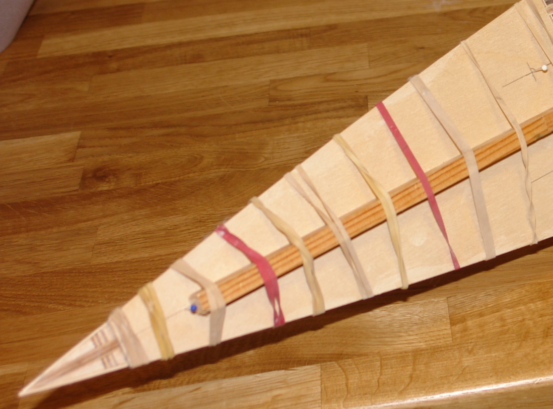
I applied glue to the hull for the entire length of the plank so that the back of the plank and the edge of the plank abutting the previous plank was glued. I didn't size the balsa. Not sure if the glue shrank the balsa - I didn't notice it doing this. I did secure the planks quite well during gluing so they were pressed hard against the backing and the previous plank- see photo.
if you have distortion in the hull it may reveal itself when you are planking the deck - mismatch between deck planks on either side (which I always think is very irritating on the eye). Better to correct it now.
-
Hi Julie
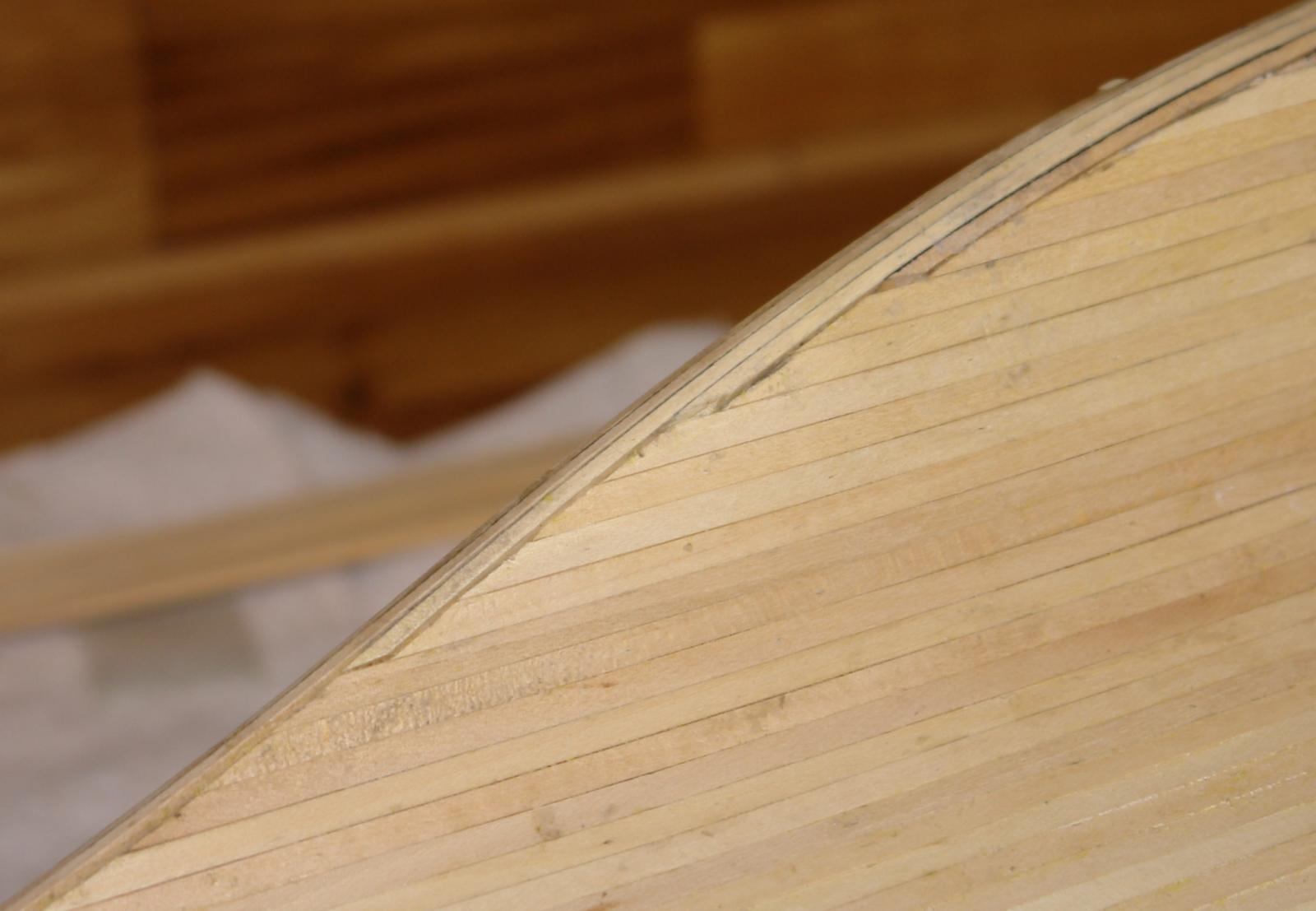
You still seems to be going well. like you I find rubbing the palm of a hand over the surface to be a good method of checking the shape.
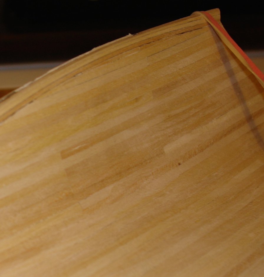
Because the balsa sands away more quickly than the frames it is very difficult to avoid some flattening of the profile between frames. Slight flattening isn't however a significant problem as it tends to be compensated by the 1st planking. In the attached photo I have done a light sanding of the 1st planked hull - you can see the areas where the frames have caused the planks to be raised. As sanding proceeds these raised areas are removed - see 2nd photo.


Like you I found the rudder wasn't the correct shape at its upper end. Also the plans show a weird discontinuity between the rudder and hull at the base of the rudder - I ignored the plans in this instance.
The instructions don't seem to cover what you do about finishing the rudder. Have you decided what you are going to do?
Keith
-
Hi Julie,
Well done so far. I am assuming you will soon starting 1st planking so here are a few pointers assuming you are still planning to start at the deck and work to the keel.
I am going to split the advise into 3 parts.
Part 1 - the first 1/3 of the hull from deck to waterline. The planks tend to want to curve in their most flexible direction. You should find that these planks go on quite easily and that with care you will get good plank edge to edge contact.
Part 2 - the second 1/3 of the hull from waterline to the merging of the hull and keel. As you progress you will find that the planks become increasingly difficult to hold flat to the backing. This is because they naturally want to bend in 2 planes at the same time - bowing in their weak direction to follow the backing and bowing in their strong direction to butt to the previous plank. This double bowing is generally seen as undesirable as it can lead to twisting of the planks resulting in a "clinker" type effect. I had some of this on my build. However being aware of the problem before I did the planking enabled me to control it to a level that could be sanded out. I have attached a photo of the "clinker" area after a light sanding.

A way of avoiding the "clinker" is to abandon parallel planing in this area and start tapering the planks. This inevitably leads to a lot of shaping and the need for closing triangular fillers.
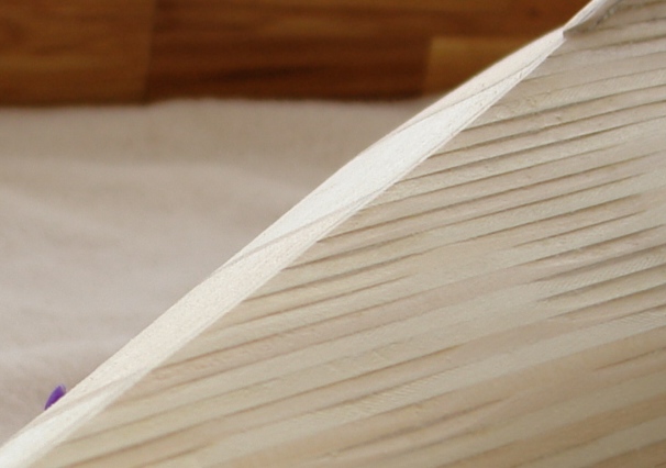
Part 3 - the third 1/3 of the hull from the hull / keel merge line to he base of the keel. As you progress beyond the hull / keel intersection the need for bending in 2 planes diminishes and bending in the weak plank direction becomes dominant. Planking therefore becomes easier once again. However the bulb of the keel starts to make its presence felt and bending the planks around its leading edge becomes impossible because of the sharp change in curvature. It is at this pint that you need to start laying the thicker bulb planks along the length of the keel (on the centre line). I have attached a photo to illustrate.

-
-
Julie
Another option (and possibly simpler) is to buy a sheet of 2mm ply and use that instead. However if you want to use backing I think you could restrict it to the larger openings on the centre line.
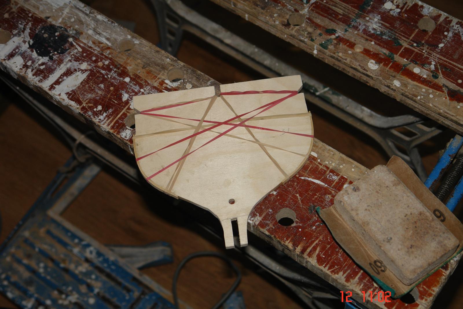
I was careful to make sure that I applied ample glue to all surfaces - including the hull backing balsa. And I did use a lot of elastic bands to hold it in place. I also used a scrap piece of wood to make sure that the centre line contacted the frames. - see photo.
The blue and white headed pins are the temporary location pins.
Keith
-
Julie,
Re diagonal planking.
I did try out diagonal planking of the mahogany second planks. I convinced myself that it would work but in the end decided to go with planks parallel to the deck because I thought it looked better.
I didn't consider diagonal planking on the 1st planks because they are thicker (less flexible), changes in curvature are significantly more pronounced and double curvature ("s" shaped) occurs in the area of the keel. This isn't the case on the picture you have posted. However try it with one or two planks as I did with the second planks.
An advantage of the deck attachment sequence mentioned previously is that the 2nd planking is displaced by 1/2 a plank width from the first (because of the thickness of the deck and deck edge plank. This means you don't get seam on seam even though the planks are parallel.
-
Julie
Clearly the deck will flex under undue pressure. What I mean by perfectly solid is that it took the deck planking without any distortion and the finished deck (with planking) exhibited no perceptible deflection under thumb pressure. I have just rechecked the thickness of a scrap piece of deck plywood and its thickness is 1.02mm or circa .050". I have also done the thumb check on my model and I can't detect any weak areas.
Regards.
Keith
-
Hi Julie
I had variations in backing thickness - Its difficult not to have this and it does not matter. I wouldn't worry about it.
I know that the deck plywood is thin but if its like mine the quality is good. I din't find any need to put backing underneath the deck and the result was perfectly solid.
Have a think about the sequence of attaching the deck.
I did:-
1, First planking.
2, Attach the deck.
3, Deck edge plank,
4, 2nd planking.
I can see pros and cons for reversing steps 1 and 2 but would probably keep this sequence if doing it again. Steps 3 and 4 need to be the final operations so the mahogany planking goes right up to the deck edge (covering the plywood and deck plank edges).
Keith
-
I think the problem with painting the hull relates to the Amati kit. It gives the option of leaving below the water line as mahogany while at the same time providing mahogany planking for the entire hull. The quality of the mahogany is good and when varnished it produces a beautiful rich finish. Lovers of natural wood tend to baulk at the thought of burying it under layers of paint.
Also the creation of a mahogany finish provides an added challenge for the modeller. Inevitably the finish has to be achieved without recourse to filler. The care and attention needed to achieve a high quality mahogany finish can be the added challenge that the modeller needs to test their skills and deliver the satisfaction they desire.
Where the accuracy of reproduction is not the primary aim the finish is really a choice for the modeller. The advice posted on finishing options may be very useful to Julie but the advice I would give is - "follow your heart".
Keith
- yvesvidal, Eddie, michael mott and 3 others
-
6
-
Hi Julie
It seems to be going well. In the end it will all be worthwhile.
Keep checking the alignment - for bow and twist. Particularly if you are working on one side first. You may need to work from both sides to control distortion.
Keith
- Julie Mo, Dimitris71, Canute and 2 others
-
5


How would you improve your Byrnes tools?
in Modeling tools and Workshop Equipment
Posted
Hi Guys
I have posted this stuff on the Jim Byrnes model machines thread - i repeat her as it also fits in with this topic.
Shaft lock to make blade changing easier:-