

Cathead
-
Posts
3,353 -
Joined
-
Last visited
Content Type
Profiles
Forums
Gallery
Events
Posts posted by Cathead
-
-
Very nice job upgrading ol' #616. I love this kind of modeling!
- Canute, Ferrus Manus and Keith Black
-
 2
2
-
 1
1
-
Keith, I have a question: do you have a photo of Lula from the front? The only one I can recall is the one from the starboard rear quarter, but you of course have far greater knowledge of the resources you're working from.
The reason I ask, is that I'm interested in the idea that Lula had separate windows (whether three or four) on the forward wall of the pilothouse. Typical riverboat practice (which I'll openly acknowledge does not preclude any other practice) was to leave the forward "window" as either a full open area or with a bare minimum of visual interference (for example, no posts between windows). For obvious reasons of visibility. To my eye, when I look at your rear-quarter image, looking through the side windows, it kind of looks to me like Lula has the standard wide-open forward pilothouse. Like these examples on two other river ferries:

So I'm just curious about your approach here, with the open acknowledgement that I may well be wrong in Lula's case because you know her far better than I do. Regardless, it's really fun to see her superstructure move toward its final shape!
- Keith Black, Glen McGuire, BANYAN and 4 others
-
6
-
1
-
Hopefully in a few years you can!
-
Paul, great question. This layout will run up to three passenger trains and four freights each way during a single "day" operating session. If the staging was fully automated I'd need 14 separate staging tracks and at least that many locomotives, an expensive proposition in both space and purchases.
Instead, this is designed as a "fiddle" yard, meaning that one operator is tasked with actively remaking trains by hand as they depart and arrive. This lets me reuse fewer locomotives and cars far more efficiently and creates an interesting job. So that duckunder is how the staging operator (essentially a dispatcher) accesses that area. It's hidden behind the backdrop and big enough to allow a standard desk chair. The out of sight setting helps create the illusion of distance, that trains are entering the main layout from locations far away.
This lets me get away with five staging tracks instead of fourteen, which would be impossible in the space I have.
-
Here's another way of looking at layout design. There's a tension between pure operational interest (lots of active switching and industries) and pure scenic interest (lots of pretty places to run trains through). This region has both, but I don't have the space to do all the possibilities justice. So there were a number of different ways to organize the layout plan depending on what my priorities were.
Here's a schematic view of the area in question. Every town sits in a small valley where some tributary to the Missouri River cuts through the bluffs, and these towns are separated by long stretches of scenic riverfront running with tall bluffs immediately behind the tracks. At the west end, the line makes a literal 90º turn to join the north-south mainline (great for a model railroader, we never get corners that neat!). At both ends of the north-south mainline, the line climbs through the bluffs to reach the high ground beyond. At McBaine, a ~9 mile branch climbed through the river hills to the larger town of Columbia.

A pure operations layout could focus almost solely on a big version of Franklin Yard, where the railroad's two main lines met and where lots of switching happened along with a busy engine terminal and passenger depot. The next-best operational locations are Boonville (which had a lot of industries for a fairly small town) and the branch to Columbia from McBaine (Columbia had more industry than anything in the river valley beyond Boonville).
A pure scenic-running layout would ignore these settings to focus on the Missouri River bridge, lots of river- and bluff-front running, and the Rocheport tunnel area. This would let the builder do the dramatic scenery justice with long stretches of track gently curving along the river, really bringing the scale and beauty of the setting into focus.
My track plan is a compromise, because I want both. I think a pure scenic-running layout would be fun to build but eventually become boring because there's not much to do long-term once you've railfanned a few times. To me, realistic operations are one of the key attractions of model railroading (in contrast to, say, static ship modeling), and I was determined to allow for this. But as a geologist and naturalist, it was unacceptable to leave out the scenic setting; at that point why not just design a free-lanced operations layout rather than a version of the Katy that stripped out all the best parts?
So through a long iterative process, I developed a way to include:
- a Franklin yard that was big enough to allow some basic operational switching while still being small enough to not dominate the room
- a Missouri River bridge that was big enough to convey the massive original span while still being small enough to fit
- three more mainline towns with minor switching, enough to allow diverse operations
- barely sufficient scenic runs along bluffs and the tunnel
Reluctantly leaving out:
- Boonville and its many industries (if I were more purely operations oriented I could swap the big bridge for this town)
- longer runs along the river (again, I could swap Rocheport or McBaine for a nice long river/bluff run)
- meaningful operations along the northern line from Franklin Jct and the Columbia branch. In both cases, I'm allowing for cars to be switched into blocks as if they were headed for those destinations, and that has to be enough.
What this lets me achieve (hopefully) is operating sessions that can host 3-4 operators, allowing for the fun social time that is such a key part of model railroading, with a diversity of jobs from through passenger trains to yard switching to local freights. While still giving fair play to the scenic setting and something of the geographic scope of this line. And including this many towns balances the operator jobs, so a local freight has enough to do to be worthwhile as an assignment, and through trains feel like they're passing through many different locations rather than just one stretch of the line.
If I had just a bit more room the first thing I'd change is to add Boonville, it's such a fascinating town, but it just doesn't make the cut. Leaving it out also simplifies operations because I don't have locals going both directions from Franklin yard.
Anyway, that's another brain dump but maybe it helps you see more of how and why I've been thinking through this project.
-
No further modeling progress has been made due to an overload of family visits, work deadlines, the onset of spring garden/orchard season, and more. So here's a little more background context to keep you all interested.
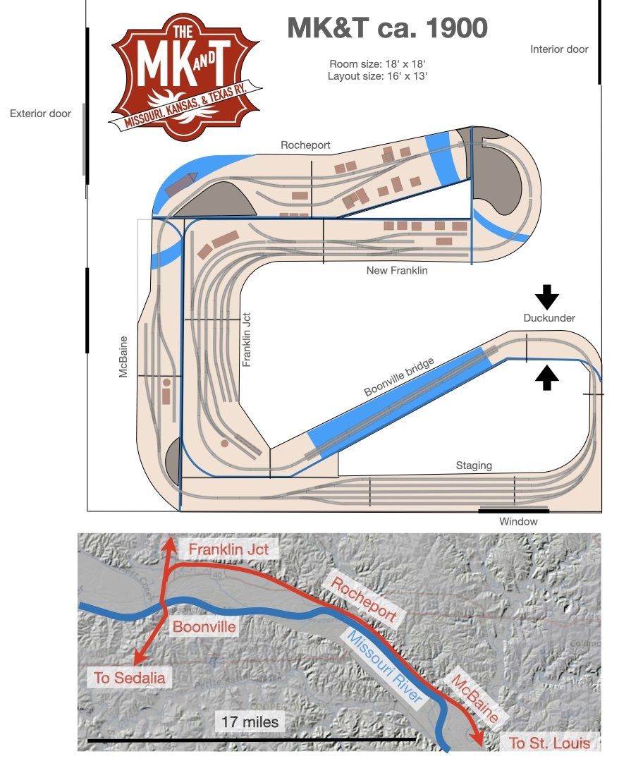
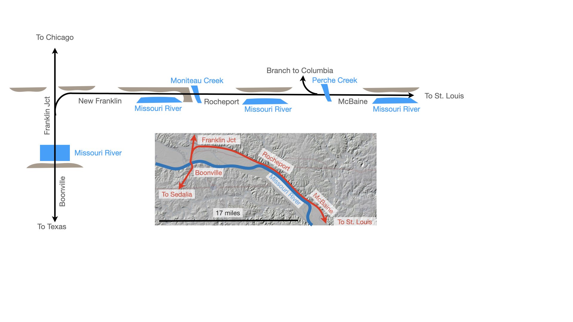
Below is a rough track plan that will continue to evolve but is guiding my work. I've spent two years researching and adjusting this and it's pretty close to my final "ideal" design. The arrangements at Rocheport and McBaine are quite accurate representations of those settings with some necessary tweaks and compression. The depiction of Franklin Jct and New Franklin follow the general pattern of the railroad there but the literal track arrangements have been adjusted more heavily to match the requirements of space and operational interest. The bridge over the Missouri River at Boonville is nearly 8 feet long, but is only about a third the length of the real thing. I plan to go through all of these scenes in more detail to discuss how I designed the track plan for each and how they match up with reality but this at least gives a loose sense of the plan. This also shows the modular design I'm following.
Below the track plan is a rough map of the real railroad's route through the modeled area, laid over a lidar elevation map of the terrain. This helps illustrate how the Missouri River valley dominates the setting, flowing through a valley over 2 miles wide at Boonville and lined on either side with tall bluffs rising 200' above the floodplain. The railroad's main line comes up across southwest Missouri from Oklahoma and Texas, through the city of Sedalia (off-layout), then crosses the Missouri River at Boonville. At Franklin Junction, the railroad splits, with the original main line continuing north toward connections with Chicago, while the newly built (mid-1890s) Missouri River extension headed east along the river valley to connect with St. Louis. You can see how the line hugs the northern side of the valley, pinched between the bluffs and the meandering river.
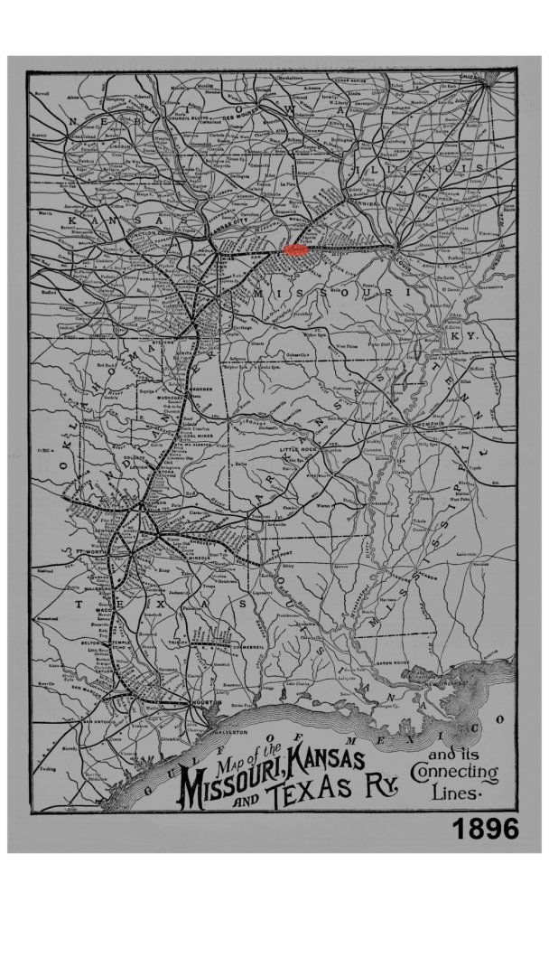
And here's a full MK&T route map from the same era, originally from the Katy Railroad Historical Society. I've highlighted the modeled area in red:
The layout's basic design is intended to provide two different but equally important (to me) operating goals: a connected loop allowing for continuous "railfan" running, but also a point-to-point design that lets trains be operated in a realistic manner from one staging yard, through the modeled portion, and back into staging again. For example, in the design above, trains leaving the staging yard to the right are heading north from Sedalia, while trains leaving to the left are heading west (railroad south) from St. Louis. When they re-enter the staging yard after transiting the modeled layout, they can simply be re-staged as a new train later in the operating sequence. Franklin yard is where freights are broken down and remade for various destinations down the line in all three directions, though I'm not really modeling the northern branch toward Chicago because I don't have space. Local freights also originate here to work the route through Rocheport and McBaine. The Katy ran three passenger trains a day each way on this line during this era, along with regular freights and livestock trains.
That will make sense to the model railroaders reading this; if it doesn't to others, please say so and I can explain in more detail. Or ask any other questions; it'll still be a while before I can get back to real modeling work so this is as good a time as any to engage in the intellectual side of this project.
- NavyShooter, yvesvidal, kurtvd19 and 6 others
-
9
-
Apparently my sense of humor is far too dry...I thought it was obvious that was satirical and utterly made-up. Oh well. The best jokes are always the ones you have to explain.
- Canute, Keith Black, GrandpaPhil and 2 others
-
 5
5
-
Actually, it was tradition for riverboat builders to carve "616" in the base of one skiff, as a tribute to the Grand Rapids, Michigan area where the steamboat skiff was first developed. Good on Lindberg for recognizing this little-known piece of American river history.
-
I agree, this kit will turn out looking far more realistic to the casual eye than the absolutely toylike King of the Mississippi. The best kit by far remains the Model Shipways Chaperon, but that's one huge and I can understand why not so many people build it for that reason alone.
Anyway, none of this discussion is or was meant to make you feel defensive about your kit choice; it was meant as just an honest discussion of steamboat design since you'd expressed interest in learning more about an unfamiliar topic. My apologies if any comments came off otherwise.
- GrandpaPhil, Ian_Grant, Canute and 3 others
-
6
-
Yeah, I was only referring to common practice on American riverboats. Obviously, for example, railroad locomotives were set up the way this kit is. My understanding is that steamboat fireboxes were normally placed at the front at least in part to allow for the extra draft needed to keep their very tall chimneys drawing. Ironically, this kit has especially short chimneys, making that less of an issue.
And yes, in most steamboat boilers the fire tubes ran through the whole boiler to provide even heating. This was one reason it was very important to keep sufficient water in the boiler; quite a few boiler explosions happened when the steamboat's engineer let the water get too low, letting the firetubes get extra hot, causing an explosion when cold water came into contact with those tubes (either through refilling too late, or the vessel rocking from side to side).
Ferrus, see what happens when you let steamboat nerds into your build?
- Keith Black, thibaultron, Ferrus Manus and 3 others
-
5
-
1
-
Yeah, as I said, I couldn't see from previous photos how the kit had things arranged. The angle on the box-cover painting makes the solid front bulkhead look like a post, or at least I assumed that's what it was showing since that's what "should" be there. Given what you've said, you've got the coal dust in the right place, even though the kit's boiler/chimney arrangement is wacky. I certainly wasn't intending to imply that you should do a bunch of scratchbuilding, I get that the appeal here is a simple kit that will look good when finished. Carry on!
- thibaultron, Ferrus Manus, Canute and 3 others
-
5
-
1
-
On 4/6/2025 at 11:43 PM, Ferrus Manus said:
Hence the unhealthy, lung-destroying layer of coal dust on the deck immediately aft of where the boilers will be
For what it's worth, since you're interested in learning more about river vessels, the firebox would typically be in front of the boilers, not behind them. That's why the chimneys (the proper riverboat term for the smokestacks) are there; they're venting the smoke from the firebox. So the biggest coal mess should be in the area in front of the boilers. At least how's how the real thing would be; this kit seems to take various liberties with accuracy and I can't quite tell from your photos where it puts the firebox.
Also, for reasons never fully defined, the deck with the boilers is the main deck, while the deck above the boilers is the boiler deck. Just how it is. Sailing vessels have their own bizarre vocabulary too!
- Keith Black, Ferrus Manus, thibaultron and 1 other
-
3
-
1
-
Nah, if he piloted on the Missouri River, nothing New York can throw will faze him.
- Glen McGuire, Canute, TBlack and 2 others
-
5
-
-
I could be wrong, but I don't think Missouri Pacific used track pans on this line. It was very much a secondary/local line for them and I can't think of why they would need to. But I should stop diverting your log into railroad stuff!
-
10 hours ago, Keith Black said:
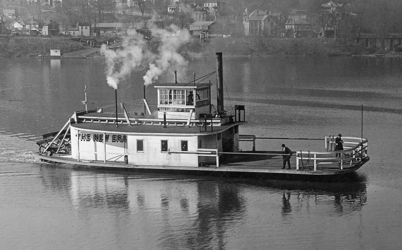
you wouldn't be drilling for drinking water in the middle of the river, my guess is they were setting pipe to get water to the tracks
Awesome observation, I completely missed the pipes sitting there. I bet you're right, and here's some fun context to support your contention. There IS a rail line right along the river bank where this is tied up, but it's not the MK&T line on the bridge in the background. It's a Missouri Pacific line running along the river (it passes under that bridge).
Missouri River water is extremely sediment-rich (hence the common nickname Big Muddy), and there's no way you'd want to run river water directly into a steam engine's boiler. But the river is underlain by a deep layer of sand, so it makes perfect sense that they'd be drilling down maybe 20-50' into that sand to get access to shallow filtered water. Also, for anyone wondering why they're doing it just off the riverbank instead of on land, the river valley here is bounded by bedrock bluffs on both sides that rise a couple hundred feet above the river and dive down deep beneath it. So you don't have to go very far in from the river before you're quickly on shallow bedrock, whereas just off the bank you're on nice thick river sand.
What I am curious about in this scenario is why they're just where they are. They appear to be well downstream of the town of Boonville (that bridge is on its northern side), where the Missouri Pacific had a depot. I don't think there would have been a water tower here. But maybe they were piping it back up to Boonville proper, since the actual riverfront near the depot was still a steamboat landing even in the early 1900s. Or maybe it's to provide water to some entity up on the bluffs (though if it was a drinking water well I think you'd put it upriver of Boonville, not downriver).
That's more than enough digression, sorry! Fun stuff.
10 hours ago, Keith Black said:Whatever its purpose it is a cute little bug, you need to put that in your train layout.
100% agree, if I get to the Boonville scene, that has to be included.
- Keith Black, Knocklouder, LJP and 1 other
-
4
-
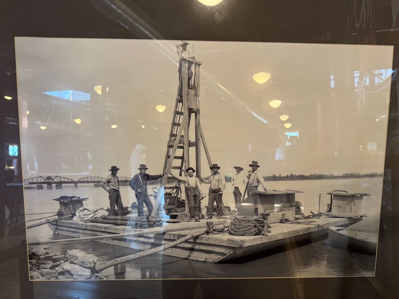
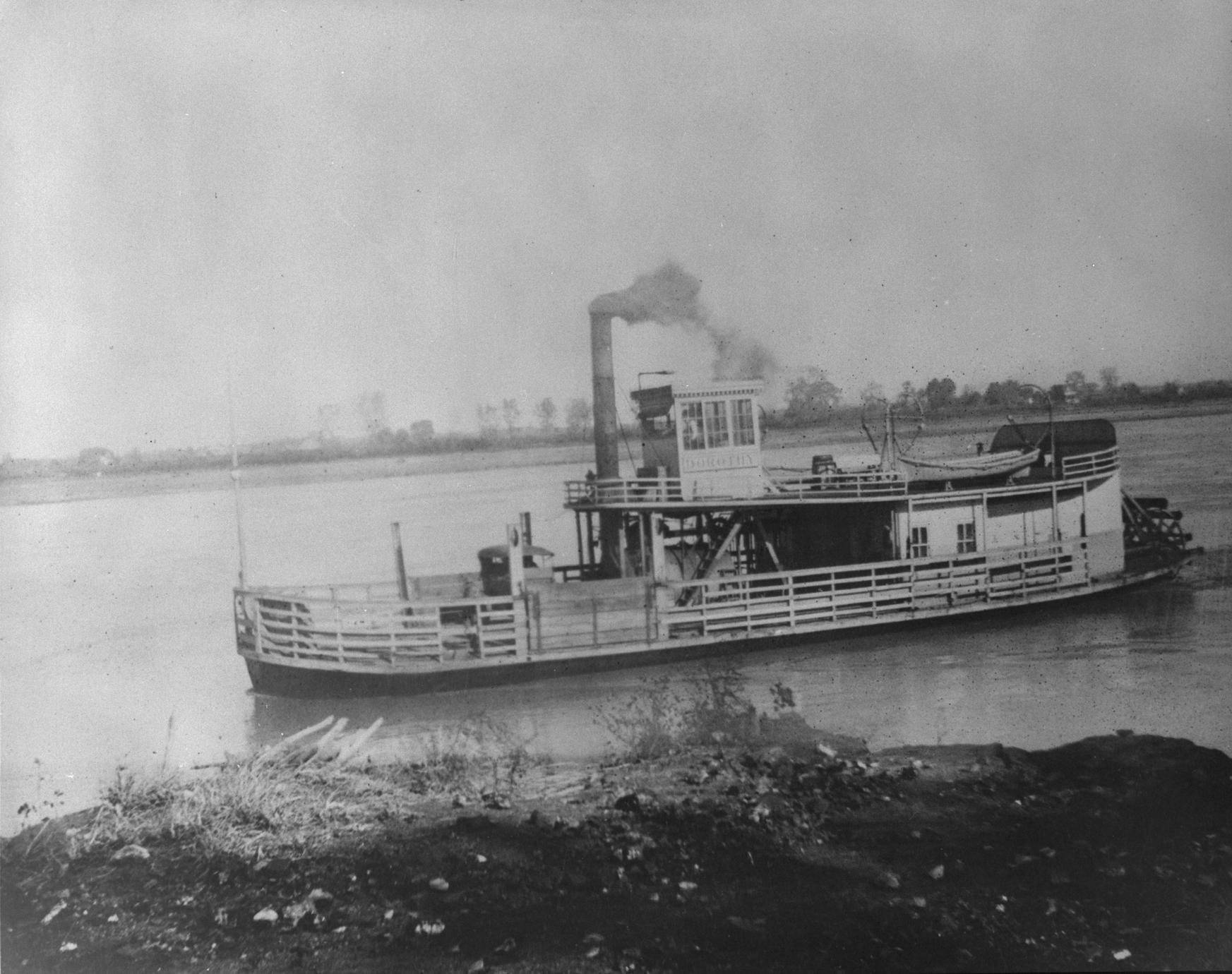
Keith, forgive me for a slight digression, but I'm betting you'll enjoy this. I was re-visiting a local museum here in central Missouri the other day, and noticed an image I hadn't thought much about before, but the last time I saw it was before your pile-driver build. Here's a small pile driver on the Missouri River at Boonville in central Missouri, undated but I can tell from the bridge in the background that it's between the 1890s and 1930s. For those following both this log and my model railroad one, that background bridge is the same rail line I'm modeling and will show up in a different scene down the road. But regardless, I thought this was a fun little comparison and worth sharing. Forgive all the light reflections.
- Paul Le Wol, Keith Black, FriedClams and 5 others
-
7
-
1
-
Good question. For the club layout above, it was a combination of commercial rock molds and hand-molded, all using Scultamold brand plaster, which is my favorite medium for texture and workability. On the Rocheport scene it'll all be hand-sculpted. Mostly forming as I go with wet plaster, with some later touchup.
I don't think I said this clearly, but the last scenery post caught us up to real-time on this project. Nothing's been done that you can't see in the images shown. So I'll definitely be covering my process once I get started on it! It'll be a few weeks because I have a few really busy weeks coming up with family visits and extra work commitments.
-
Yep, if you look back at the "context" shots from Rocheport, you'll see how complex the rock faces are there. Horizontal bedding, but shot through with layers of chert nodules and highly variable surfaces due to the karstic nature of the area. Also different geomorphology as you go up in the sequence from track level. It'll be a fun challenge. I also feel that the best scenery balances accuracy and realism. For example, some features can be accurate but "look" wrong to a viewer's eye, and my goal is for things to "look" right more than "be" right. A great example is lowing the height of the bluffs, even though that means I can't incorporate the entire stratigraphy there at scale. A 200' bluff in this scene would look toylike without the horizontal scale to match, no matter how accurate it is.
- Keith Black, Egilman, Paul Le Wol and 3 others
-
6
-
I agree, and now the bar is even higher with you following along! Here's a few hints, from scenery work I've been doing at a local model railroad club depicting this region as well (though not exactly the same locations). The photo quality isn't great but it's still some context.
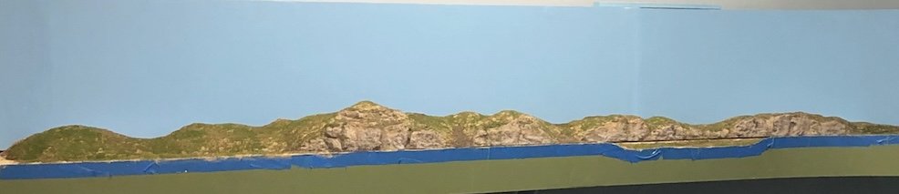
A core thing for me in making realistic rockwork is NOT to make a solid wall. Almost all real rock exposures, even those that have been blasted, have a lot of texture and variability. Rock faces are almost always broken up by scree slopes, soil-covered areas, etc. The above shot shows what I mean; to my eye this is far more realistic than a single slab of rock all the way along this scene.
Here's a closer look at part of this face:
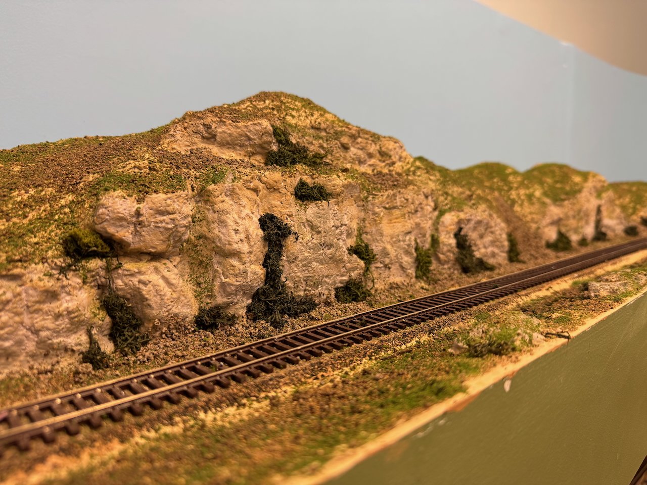
This area is limestone as well, and though the color balance here is terrible, the rocks are washed with both grey and tan shades to capture the actual mix of weathered and fresh faces in this formation.
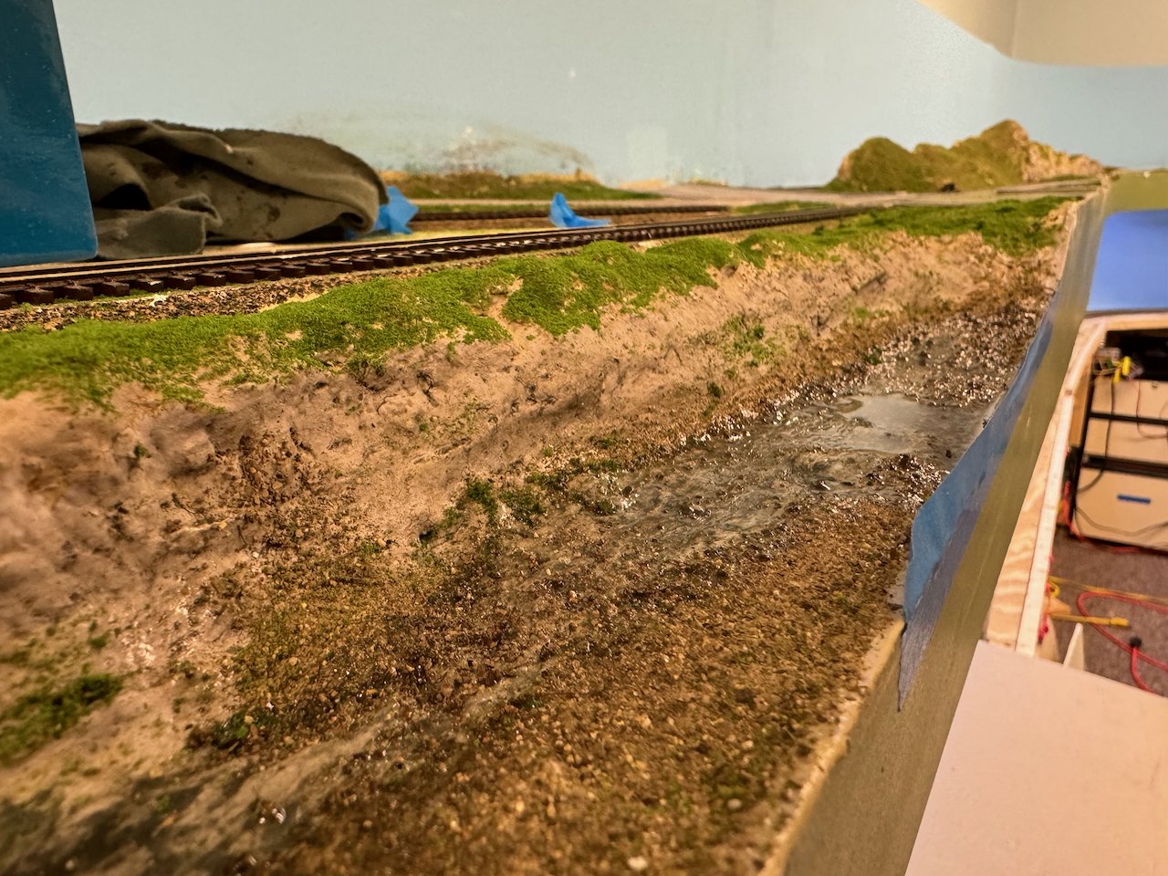
Below is yet another bad photo of a local creek bed. I was really constrained on this one because the benchwork pattern was set for this before I joined the club, and I wouldn't have laid the creek out as a straight-sided slab, but I did what I could with it. Creeks are here are routinely lined by nearly horizontal beds of limestone, giving long linear runs of rock along the water, with coarse gravel bars separating pools.
And here's a broader shot showing how even partial scenery work can come together:
All of these scenes need vegetation, which will also help tie the scenes together AND further break up the rock work. But it's been good warmup work for my own project. The way my plaster shell has been laid out is far from random and I'll talk more in a different post about some of the specific choices I made in shaping those areas with reference to the real scenic setting.
-
As it turns out, Mrs. Cathead is fully on board with all my modeling endeavors, she shares my interests in history and transportation and enjoys going train-watching and towboat-watching with me. She'll probably get involved in the more detailed scenery work, if nothing else because she's also a geologist and has Opinions about getting the landscape right. She's also a botanist and will definitely be involved in selecting and harvesting the various natural scenic materials we'll be using later on. She loves the Katy Trail too (we rode the whole thing together) and very much approves the idea of having an operating piece of its living history in the back bedroom. She also used to be an active researcher on the Missouri River so everything about this whole corridor is a shared love for both of us.
-
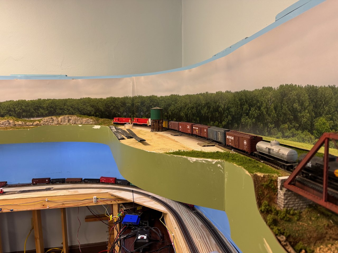
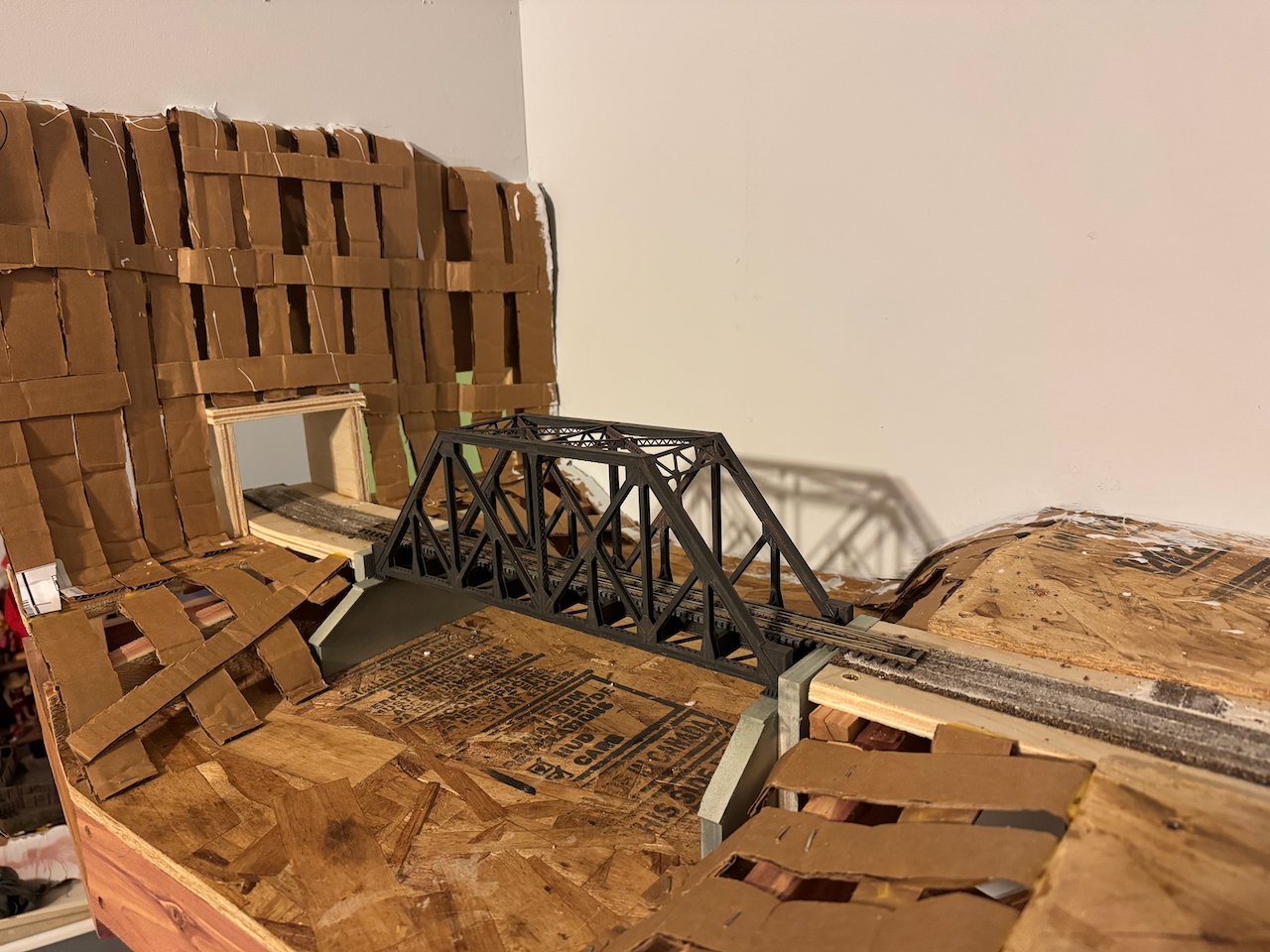
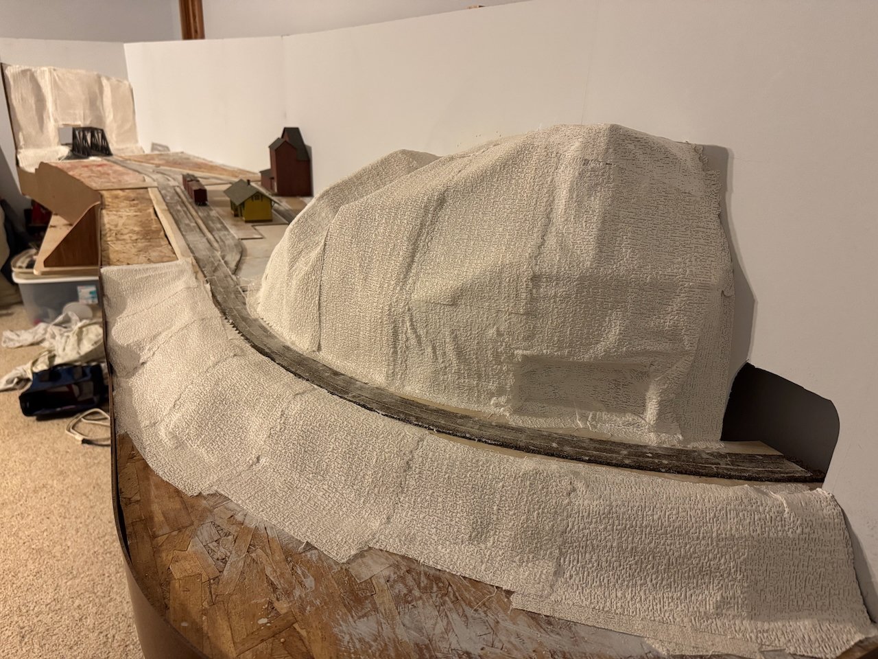
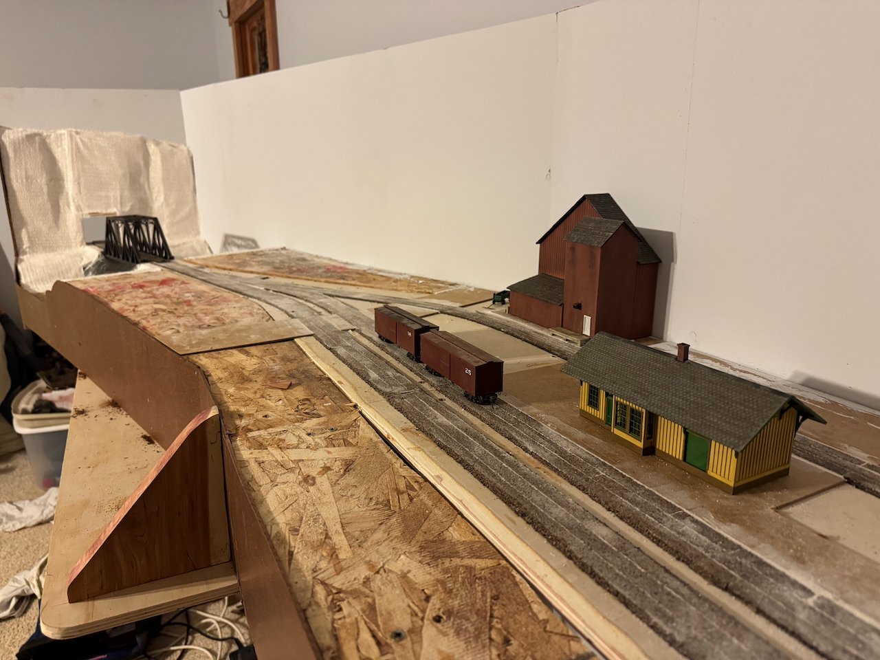
Continuing the scenery, I began working on the more robust parts of the landscape by installing webs of cardboard strips shaped to roughly outline the terrain I wanted. This is a tried and true method that gives a lot of flexibility and uses easily scavenged material. It'll be hard to recognize in photos but, as a geologist, I put a lot of thought and planning into shaping this terrain to match the real landscape here. As stated before, Rocheport is bookended to the west by a high ridge that the railroad tunneled right through, and to the east by a long series of high bluffs parallel to the Missouri River, with the rail line sandwiched between rock and river.
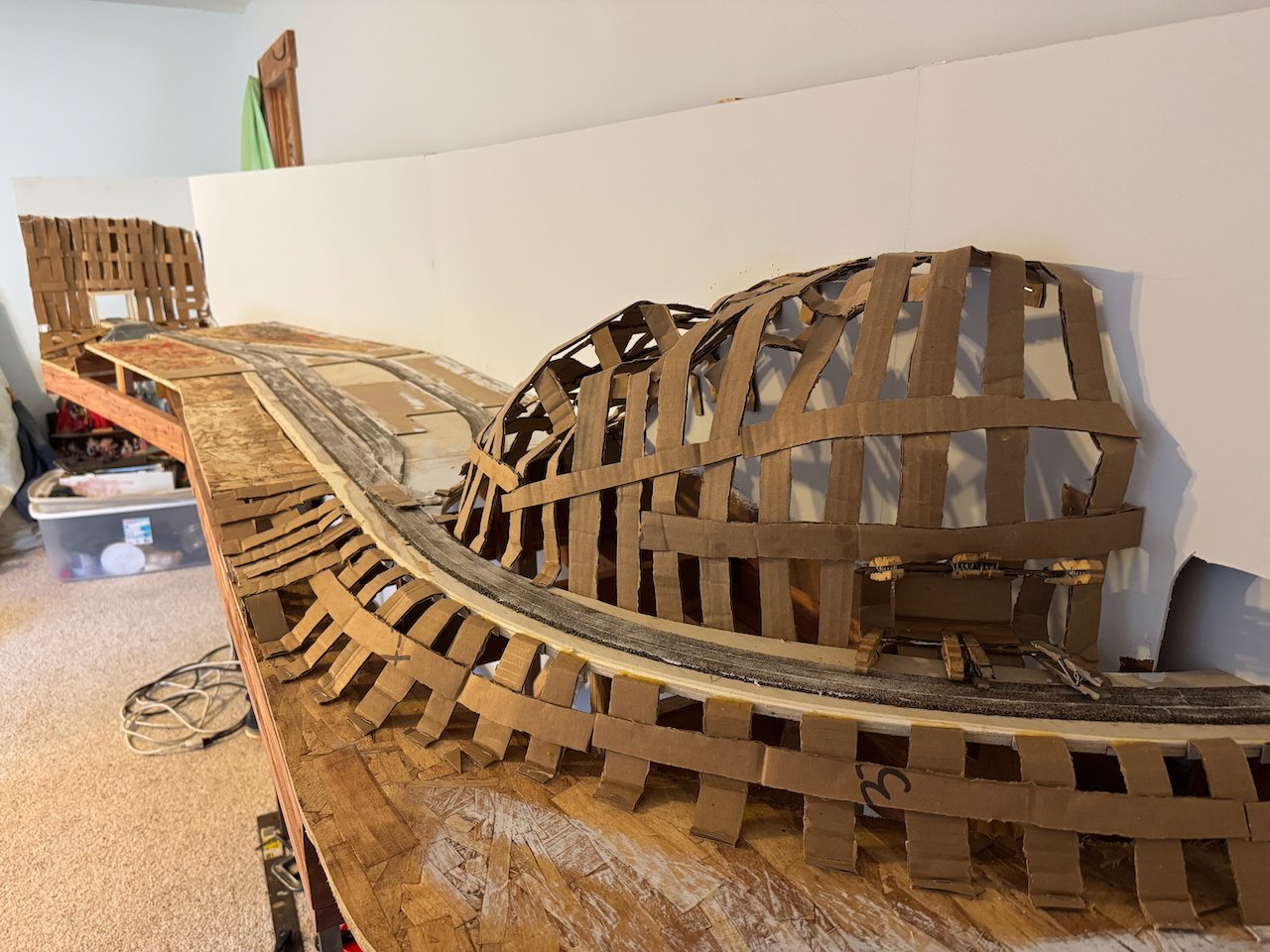
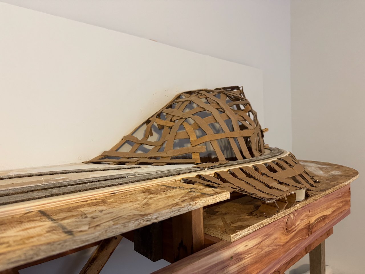
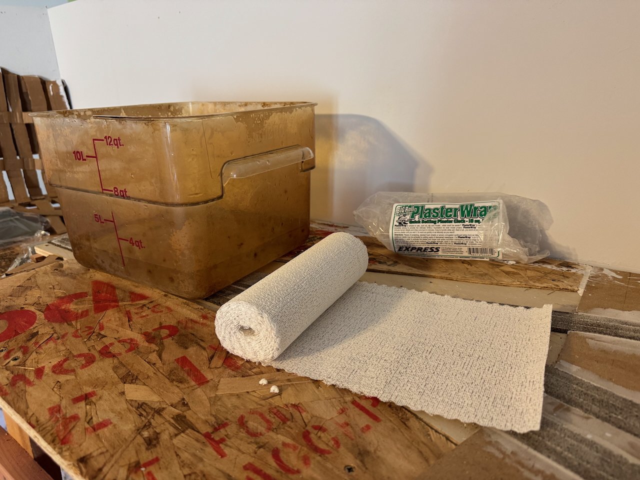
With the webbing done to my liking (including some adjustments), I began using plaster cloth to make a solid base layer. The old-school way to do this was to mix up your own plaster and dip paper towels in it, but this was always super-messy and hard to get amounts right. The more modern approach involves various products that embed a light paper roll with dry plaster, and all you have to do is dip it in water. Virtually no mess and a lot easier to do.
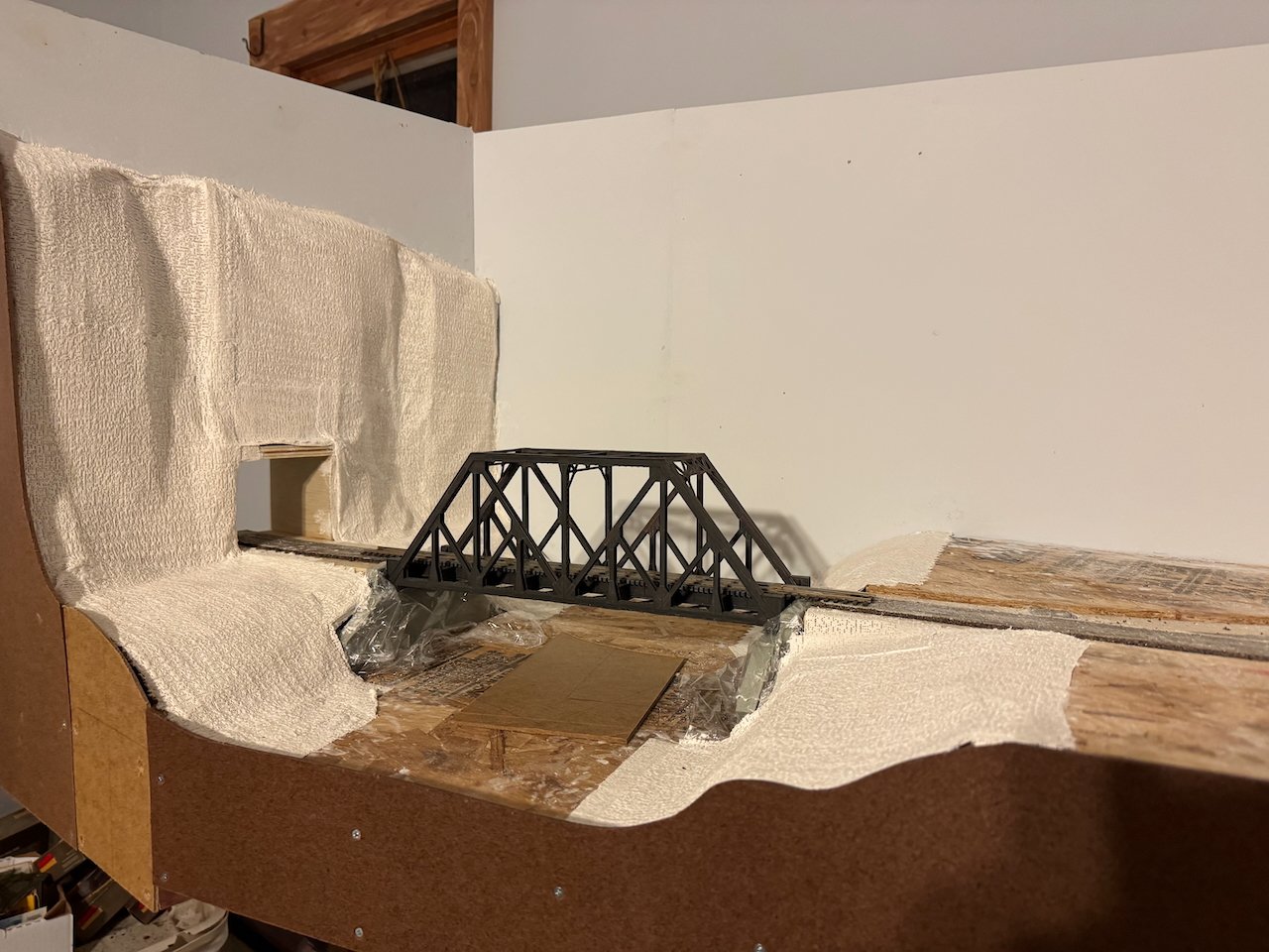
You may have noticed the odd rectangular indentation in the bluff on the far right side of the scene. That's a specific local feature; the limestone in this region is pockmarked with karst features like caves, springs, etc. I'll be including some minor examples on the bluffs, but there was/is a larger cave-entrance overhang at the base of the bluffs right along the tracks. When this line was being built, the railroad walled in this opening to use as an explosives storage area. It remains today as a notable landmark along the modern rail trail, and I just had to include it. Here's what it looks like today:
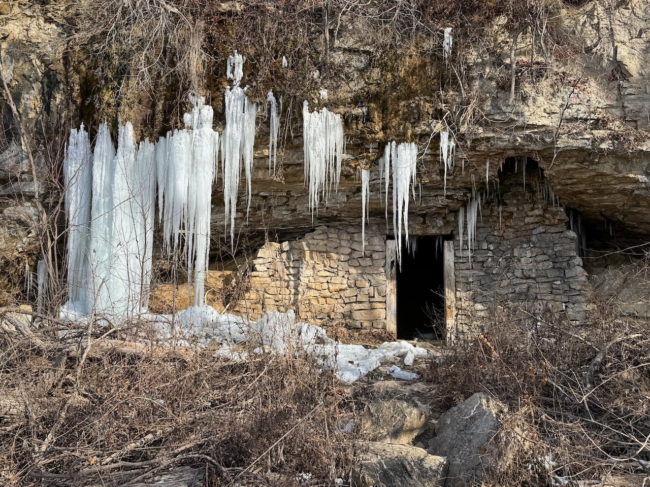
So that'll be a fun mini-scratchbuild!
Next stage in the scenery is to start using plaster to really form the bedrock bluffs, river banks, and essentially seal in the landscape the way I want. This will take a while.
Other notes:
- I didn't really photograph the process, but you'll notice that the backdrops were installed. They're currently primed but I won't finish them until more foreground scenery is done.
- You'll also notice that I installed the fascia boards that seal in the front of the layout. Like the backdrop, I won't paint these until more scenery is done.
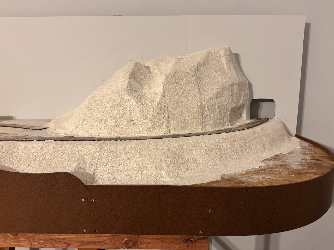
- The bluff on the left side, through which the tunnel runs, is pretty close to the actual scale height of the ridge there. It looks a bit "model railroad" if you don't realize it's exactly how the real thing is.
- The bluffs on the right side, along the Missouri River, are less than half the scale height of the real thing (on the layout they're a scale 90-100' high, in real life they're 200-300'). They still look a bit abrupt because of the horizontal shortening I had to do, and one of the scenic challenges here was finding the balance between making this scenery dramatic enough to capture the feel of the real thing, but not so dramatic that it looks "fake". I wish I had four more feel of horizontal space to make a really nice run of bluffs, the real railroad parallels these towering features for miles, but this is the best I can do.
Thanks for all the likes, comments, input, stories, etc.! I'm really looking forward to two things: getting some color on this scenery, and getting tracks laid so I can see some motion here! And I hope you'll enjoy getting there too. Soon I hope to write up some more background stuff to provide more context for the project. But I appreciate you all!
-
Jack, it's not clear from the photos and I didn't take any while assembling the benchwork, but it is a modified L-girder approach. The support frames are L-girders, on which the modules sit. I can always screw the modules down onto their support frames (though the L-girders) if desired, but it hasn't been necessary as they sit comfortably of their own accord and not screwing them in makes it easier to move them around as I continue work. But someday when I declare things "done" I'll probably drive a few holding screws in and then it becomes a really solid construction.
Also, I've used homasote in the past but chose not to this time. Thanks for your perspectives!
- Egilman, Old Collingwood, mtaylor and 4 others
-
7
-


Lula by Keith Black - FINISHED - 1:120 Scale - 1870s Sternwheeler Supply Boat for Floating Pile Driver
in - Build logs for subjects built 1851 - 1900
Posted
Keith, thanks for the update. I know it can be hard to share stuff like that and it's thoughtful of you to worry about US! Certainly the "it's your model" rule applies and no comments were intended as criticism, just ongoing discussion of the modeling process. It is and will be a fantastic model! I know it'll be extra hard on you trying to prepare for Maggie's welfare while you're under the knife, so hang in there. We're all pulling for you.