Cathead
-
Posts
3,555 -
Joined
-
Last visited
Content Type
Profiles
Forums
Gallery
Events
Everything posted by Cathead
-

2021 NRG CONFERENCE
Cathead replied to kurtvd19's topic in NAUTICAL RESEARCH GUILD - News & Information
Just in case, here's the email I received: I'm sad to say I'll have to miss this live due to a commitment that's coming up. I assume it'll be recorded and offered for later viewing? -
I have nothing intelligent to add but feel the need to thank all the smarter people out loud for such a fascinating discussion.
-
Thanks for sharing that, I didn't know about it, but then I rarely make it to St. Louis being more of a Kansas City person. My wife, a former research scientist, was working on the Missouri when a barge broke free during high water and headed downstream, threatening various bridges as well as the research vessel. It was a scramble to corral the thing since the Missouri has very little navigation traffic and so very few resources available for such an effort.
- 1 reply
-
- 4
-

-
Congratulations! May you enjoy many years of gazing at it.
- 53 replies
-
- 1
-
-
- rattlesnake
- model shipways
- (and 1 more)
-
This might be crazy, but would it be possible to avoid the need for drilling and simply apply external details on either side of the planking? No viewer will ever be able to tell whether each rivet lines up through the plank if reasonable care is taken on spacing. This would potentially let you prefabricate roves and simply glue them in place, removing the need for complex clenching in tight spaces.
-
BlueJacket has three nice-looking tug kits, the Lackawanna, the Seguin, and a generic Diesel Tugboat, developed at different skill levels depending on what you're looking for. I've built their lobster boat, which came out quite well. Their catalogue has other work boats as well.
-
Welcome! As someone who transitioned into wooden ship building from plastic kits (primarily aircraft and model railroading), I'll warn that the learning curve is pretty steep. Wooden ship building is a very different skill set from even the most complicated plastic kit. It's quite doable, just be aware that it's more of a transition than it seems. On the other hand, a plastic ship kit will use many of your existing skills, just with a lot of fiddly detail like rigging. You might considering starting with something simpler than a full-on ship of the line or galleon, to gain some perspective before you tackle something you're not ready for. A smaller, simpler project won't delay your dreams long but will help prepare you to achieve them!
-
Yes, I absolutely milled them thicker than ideal for that very reason. This did make the actual planking a bit harder to get right (leading to some of the clinkering effect as it's difficult to get thicker planks to take a complex curve) but also gave a wider margin for error. Once could argue that just milling them thin in the first place would have let me do a better job in the first place, but that carries its own risks and this is what I chose to do for better or worse. Also, since I knew my thicknesses wouldn't be entirely consistent due to the lack of a thickness sander or equivalent, I figured it was safer to go thick than end up with useless too-thin segments. Our red cedar has an interesting color for furniture and other larger-scale building, but is close to worthless for model building since the grain is so large and it's super-soft. Learning to work with cherry instead of basswood has been an education. I have a variety of other woods stored up to play with in addition to cherry, maple, and walnut, including some oddball natives like redbud and hackberry. All part of the fun of learning new things.
-
Fantastic! Thanks for explaining the considerations regarding weight vs. volume in the holds, something I'd given little thought to with regard to ship design.
-
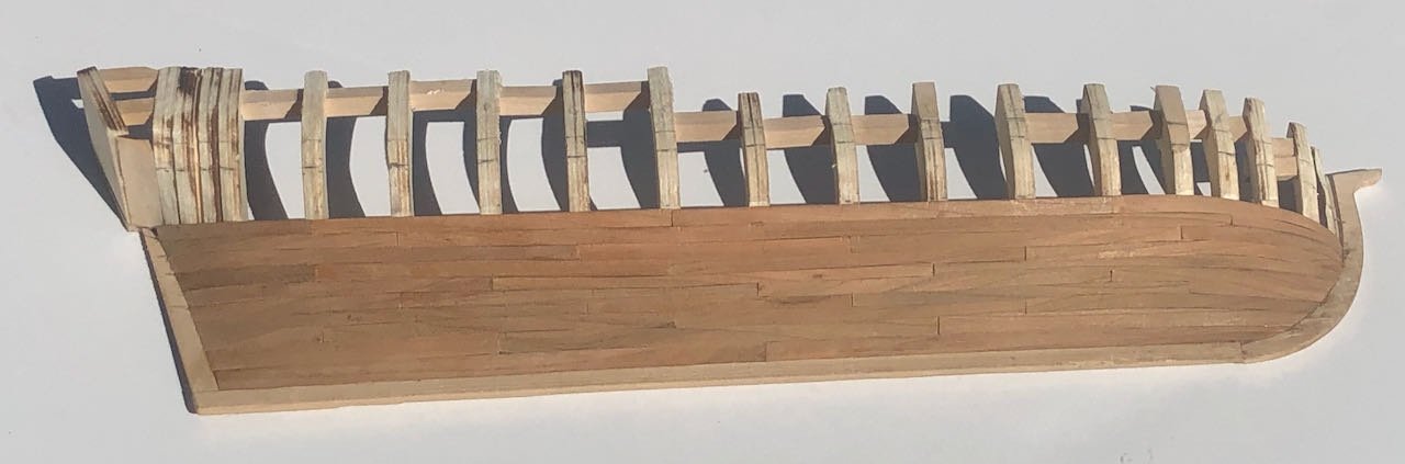
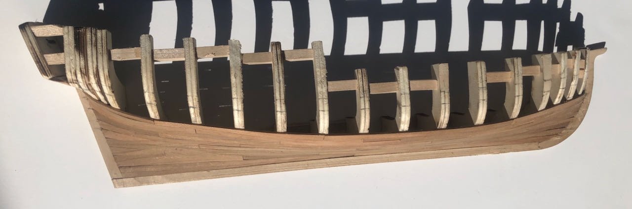
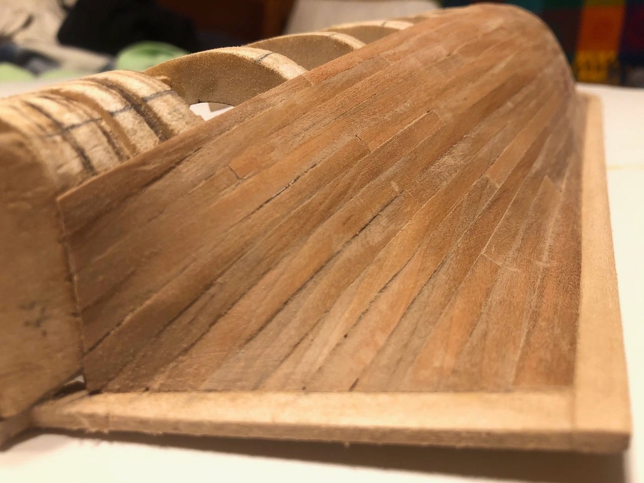
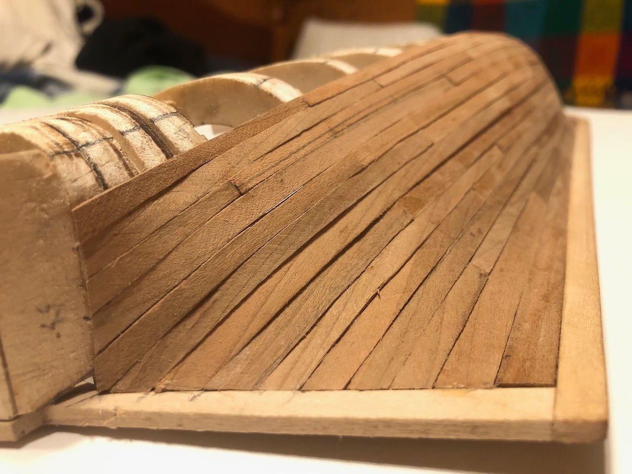
Exactly a month later, I manage to have an update. The planking is complete up to where the wale starts. This is as far as I'm going in cherry; the wale will be walnut and all the planking above in maple. I think this will make a nice color contrast on what is, after all, a somewhat artistic model. Below are two before and after shots showing the effects of a first sanding on the cherry planking: Photos sure do pick out every flaw, don't they? Others' projects have been cleaner, you can really see the unevenness of my planking. Some of this I put down to milling my own wood, some just to the fact that I'm not an artisan, just a happy muddler. Learning some good lessons, which is kind of the point. Now to start on the wale, which I'll do in two layers as suggested by the instructions. Thanks for sticking with me.
-
Andrew, I'm so sorry to hear that. I've been in the same position of trying to find purpose and value in the things a loved one leaves behind. However, this thread probably isn't the best place to ask your question as it's devoted to a single build of this model and hasn't been updated in almost a year. You might consider posting in this thread, a general discussion of all riverboat-related items, where you're likely to find a larger audience of people interested in such models. Also, have you considered trying to finish it yourself as a tribute to, and memoriam of, your father? You'd find a lot of support here if you did.
-
Any further progress? I miss following this project.
-
If you like historical fiction, Ken Follett's cathedral-building epic The Pillars of the Earth is subtly built around the sinking of the White Ship, in a way that pays off very satisfyingly at the end but I can't say more without providing a spoiler. The actual writing can be a bit purple at times but it's a satisfying read for its breadth of character and historical context. Personally I think his later writing went off the rails a bit but this early book is quite good. I love how well the castles match the seals, it truly brings the images to life. There's something very satisfying about turning 2D art into 3D art in this way.
-
Sorry, I've never bought a case. Google turns up various options.
-
Just saw this. How cool! Thanks for sharing.
-
So often, in steamboats, the rule is "anything reasonable was probably done somewhere" (and sometimes unreasonable). I agree that the boiler and hurricane decks look like they have canvas, and it seems more likely that those weren't painted red, so a natural canvas color would seem appropriate there? With a dull red for the main deck as a contrast? In the absence of better evidence I'd say choose what looks attractive to you personally and what you can reasonably justify.
-
Just catching up, beautiful as always. To clarify an earlier discussion, I've used pastels for both weathering and primary color on various ship builds as well as model railroad projects. On Arabia, the deck planks were colored by pastel while the main white color was paint. On the Viking ship, the shields were primarily colored pencil while the sails were layered pastel and colored pencil.
-
Sorry for slow reply , been off grid and now browsing at airport on phone so hard to study diagrams or write long reply. Will try to help more later this week. Just wanted you to know that you weren’t being ignored.
-
Nice start on a neat model. Hope you're still working on it.
-
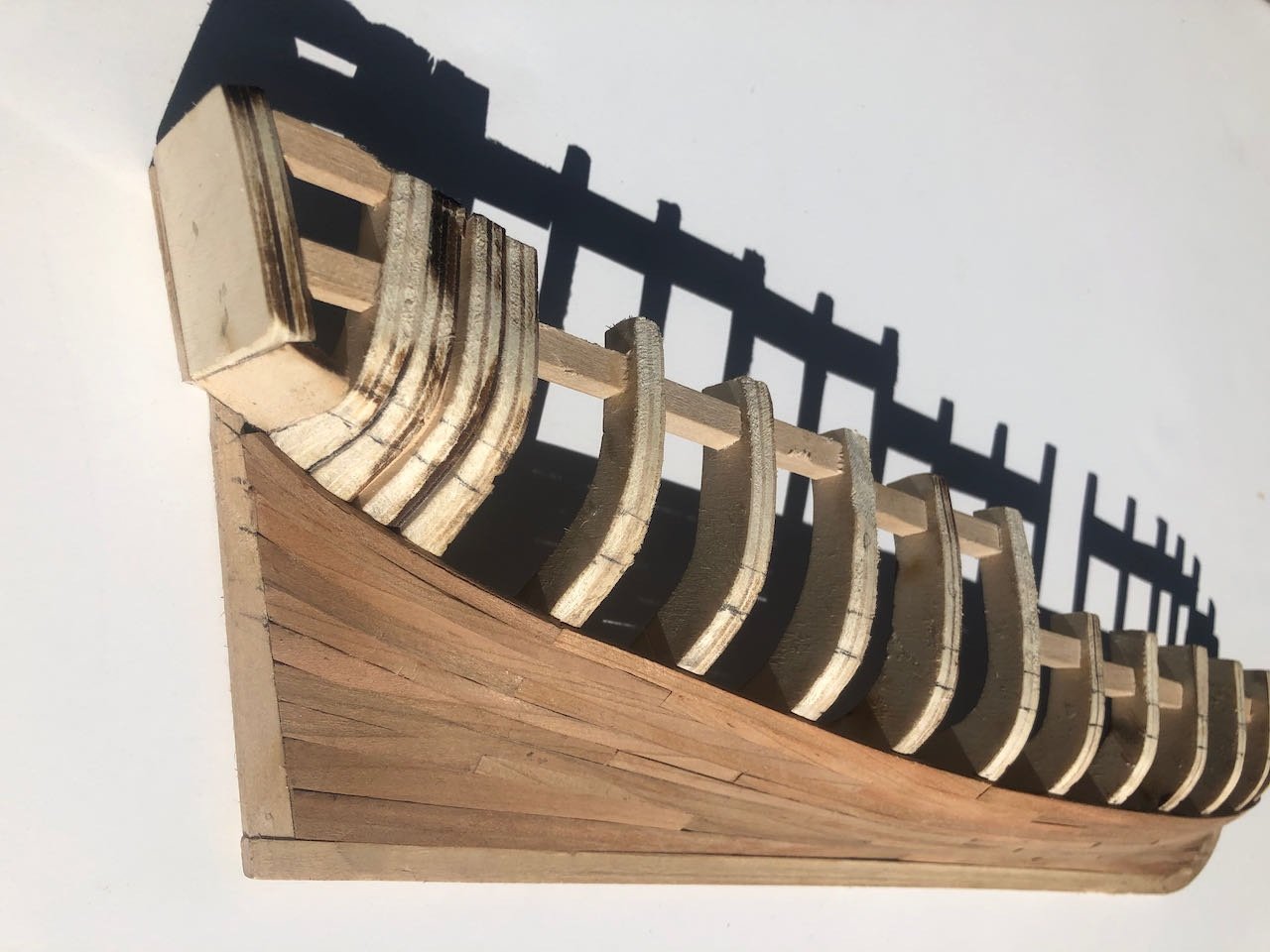
I've already beaten the crap out of the keel, sternpost, and stempost, and wish I'd remade those in maple before getting started. As it is I'm considering trying to add a thin veneer or something, depending on how well the damage sands out. Some of that damage comes from my stubborn insistence on building this as a loose model (not attached to a build board as in the instructions), which definitely exposes these parts to harm but I'm finding makes many parts of the process much easier. Sounds like a good plan. I really think this is going to clean up well with a bunch of sanding.
-
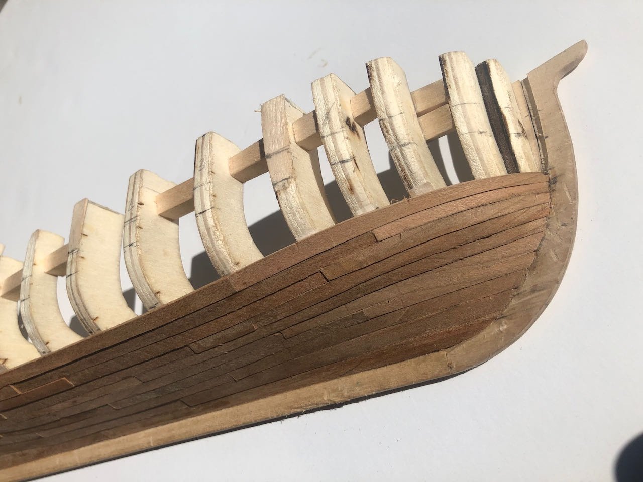
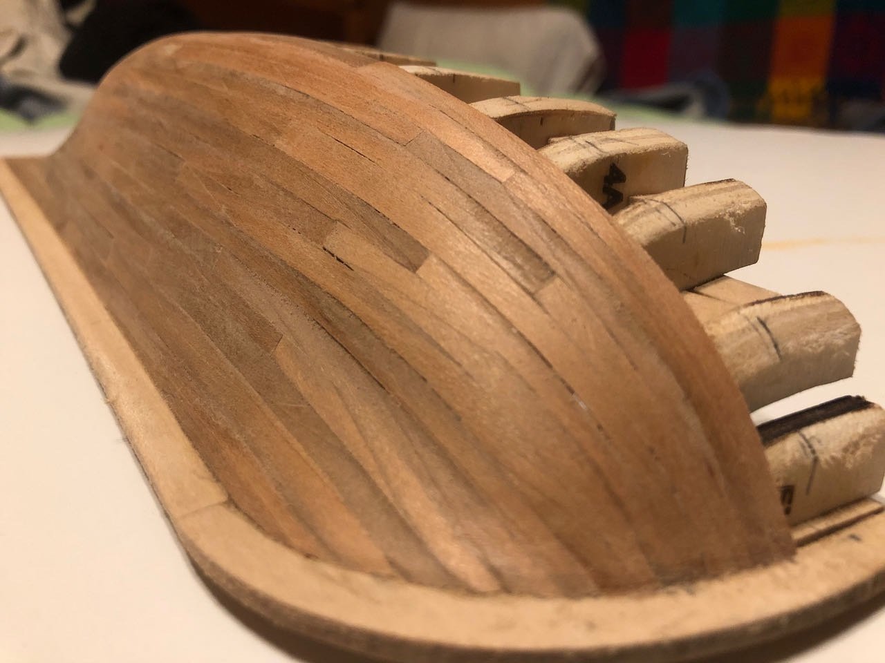
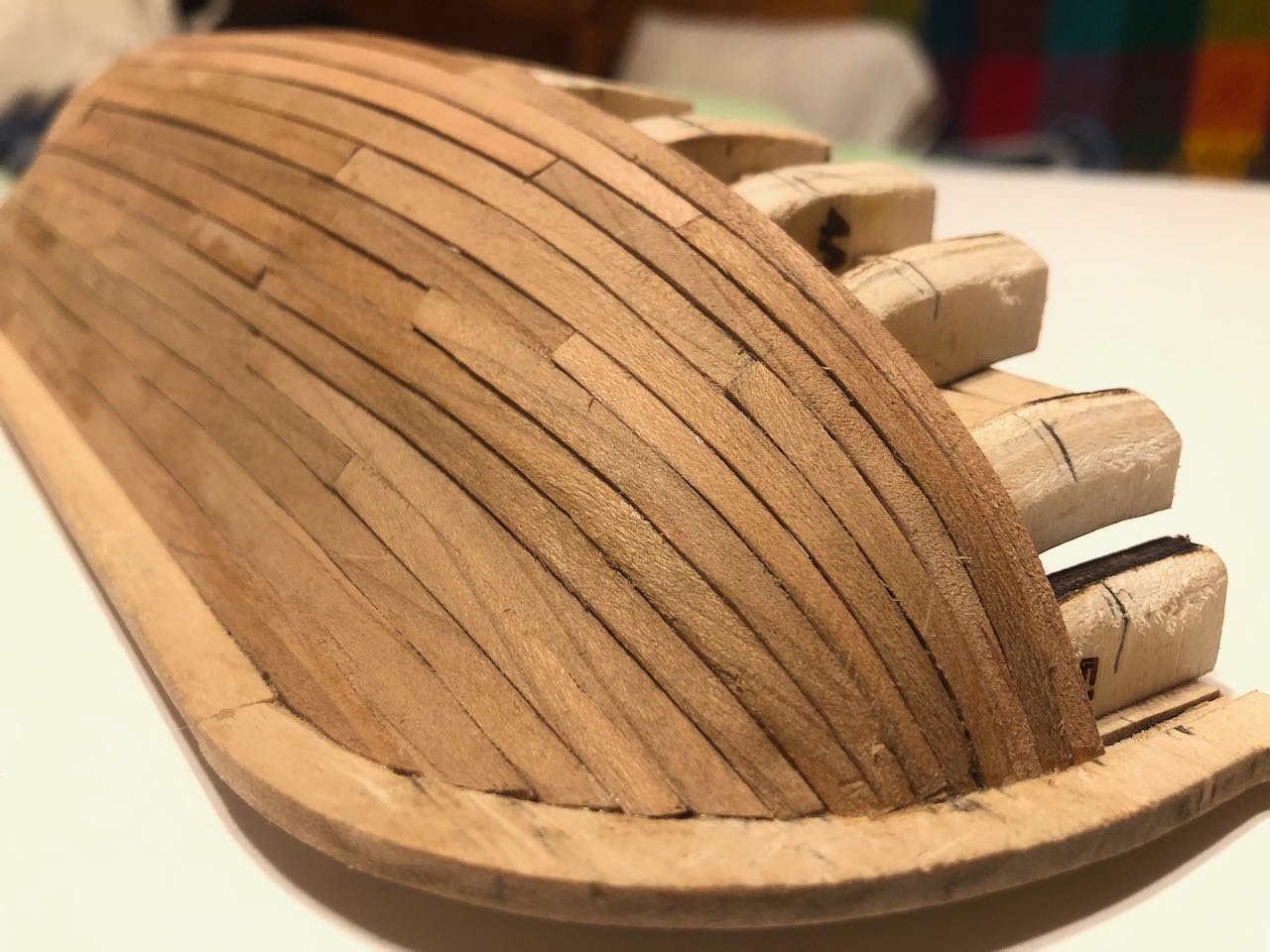
I agree that the directions are pretty difficult to follow regarding how to handle the complex planking around the counter, and none of the photos really capture it in progress. I had to study a lot of different images to even get as far as I have.
-
It's been over a month since I updated this, so here's the current status. I'm 2/3 of the way through the lower planking (below the wale). I haven't been in the mood to make updates, partly because life has been stressful and distracting, and partly because I don't think plank-by-plank updates really add anything to what's already well documented for this project (and planking in general). I have mixed feelings about the results. I just haven't been able to make the planking runs as consistent in width as I'd like. Seems like a mental block or something. I know what I'm supposed to be achieving but there's a lot of variability that just seems to have crept in. I honestly think I did a better job planking my revenue cutter than here, where I'm paying more attention. Some of this may be due to working with the home-milled cherry, which has variable width and a fairly coarse grain, which sometimes makes precise cutting difficult. Here are two closer views of the bow and stern: You can really see the varying plank thicknesses that result from using the Byrnes saw but having no thickness sander. I intentionally milled my strips a bit thick to allow for final sanding, so I think this will look a lot better as a finished product than it does now. I haven't used a stealer at either bow or stern, even though I knew I was supposed to. Somehow it didn't develop naturally from the way my planks flowed. I see a lot of mistakes and problems overall, and plead (a) a relative lack of experience with this process and (b) a really distracting period in my life right now. Even when I sit down to work on this, my mind isn't really focused, so I'm just sort of drifting through this. I am learning some things, and I think the final product will be reasonably attractive. But I thought I would be doing a better job. Here's one more shot of the current hull. Four planks to go before the wale, and then things get a lot easier. Thanks for looking in.