Cathead
-
Posts
3,538 -
Joined
-
Last visited
Content Type
Profiles
Forums
Gallery
Events
Everything posted by Cathead
-
 I'm working on this project now, and catching up on various other logs. Did you keep working on this? The snapped-off frames would certainly be frustrating, and I'm thinking ahead to how to stabilize this sufficiently when I get there. It also looks like your frame surfaces came out pretty uneven, given the major shimming you're doing? That's how mine is as well. Anyway, hope you haven't stopped working on this.
 -
Great work! I love it when a model becomes one's own through tweaking. As to the chimney band question, chimneys were built from metal sheets coiled into hoops, which could only be made so wide, so the regular bands likely reflect the joints between those. On the photo of America that you shared above, you can clearly see the regular spacing all the way up. I'm not sure about the exact function of the thicker bands, your suggestions all seem plausible.
- 86 replies
-
- 1
-

-
- king of the mississippi
- artesania latina
- (and 2 more)
-
Welcome back, congratulations on your degree, and I look forward to enjoying your return to the hobby. The black makes a nice contrast with the deck.
-
Personally, one reasonably accurate set seems sufficient to me, since pure accuracy isn't attainable in this kit and one was very common. You'll improve the looks a lot just by getting the one set right.
- 86 replies
-
- 1
-
-
- king of the mississippi
- artesania latina
- (and 2 more)
-
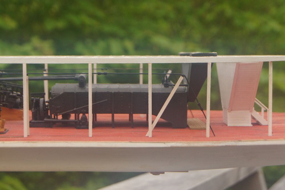
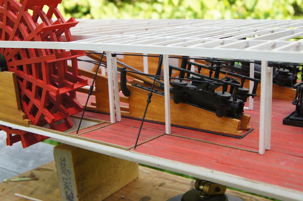
Yeah, you can't go too wrong basing your upgrade on that image. Looking closely, I think she may even have two sets of parallel longitudinal chains, one above the other. And I agree, she does have a couple lateral chains, especially visible around the boiler area. The lateral chains aren't necessarily due to a lack of structure between the decks; that was true of many smaller sternwheelers. They're just part of the inherent need to stabilize a lightly built flexible design without a lot of heavy timber bracing. In particular, this vessel (like many) has "guards", the extension of the main deck out beyond the hull. They're relatively narrow here, but they're there. Those areas were commonly used for cargo storage, you can see piles of lumber for example, so there was a lot of weight on an extended deck with almost no structural support. So the lateral chains are part of the solution to placing all that weight out there beyond the hull. In contrast, the AL design has almost no guard width, which is why I suggested it may not have needed lateral chains (though adding a few would still give visual interest and wouldn't be "wrong"). If there's one truth in steamboat design, it's that things were done lots of different ways and there was no one specific design. These didn't come out of Royal Navy dockyards with standardized plans. So you can't go too wrong picking an image/prototype that you like and using that as a base for whatever improvements you want to make.
- 86 replies
-
- 1
-

-
- king of the mississippi
- artesania latina
- (and 2 more)
-
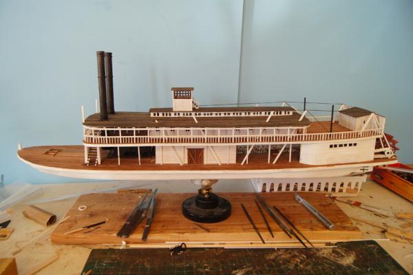
Bob, if you want to learn more about hog chains, you might consider watching a short segment of a talk I gave on steamboat design earlier this year (shameless self-promotion alert!). The whole thing may be of interest, but at 25:05 I specifically discuss hog chains with a few diagrams and photos (https://www.youtube.com/watch?v=Rj7yzkd9geg). Google will also turn up some useful basic information. Hog chains were solid iron rods, not wires, ropes, or chains. And they should run in a straight line parallel to the longitudinal axis (or at 90º to it in some vessels that needed lateral support, which wouldn't really be true for yours), not bend inward anywhere. Though, as you say, absolute historical fidelity isn't really a concern here so it may or may not be worth correcting that. Also, they weren't anchored above the deck (as to an eyebolt) but down into the hull or at least through a deck beam. So, for example, here is a longitudinal chain on the Arabia (note the turnbuckles): And here are a couple lateral chains: If you're interested in making the hog chain assemblies a bit more accurate without too much fuss, I'd suggest two changes: (1) shorten the posts so the chain runs roughly parallel to and just above the surface of the upper deck and (b) run them all the way down to the main deck (if you can) and just insert them into a hole in the deck rather than to any eyebolts. For example, here are longitudinal chains on the Bertrand: There was more than one arrangement possible, but they really shouldn't go as high as the kit has them.
- 86 replies
-
- 4
-
-
-
- king of the mississippi
- artesania latina
- (and 2 more)
-
Just read through your build, I love the extra details that help bring a kit alive and give it a personal touch. A very attractive model thus far.
-
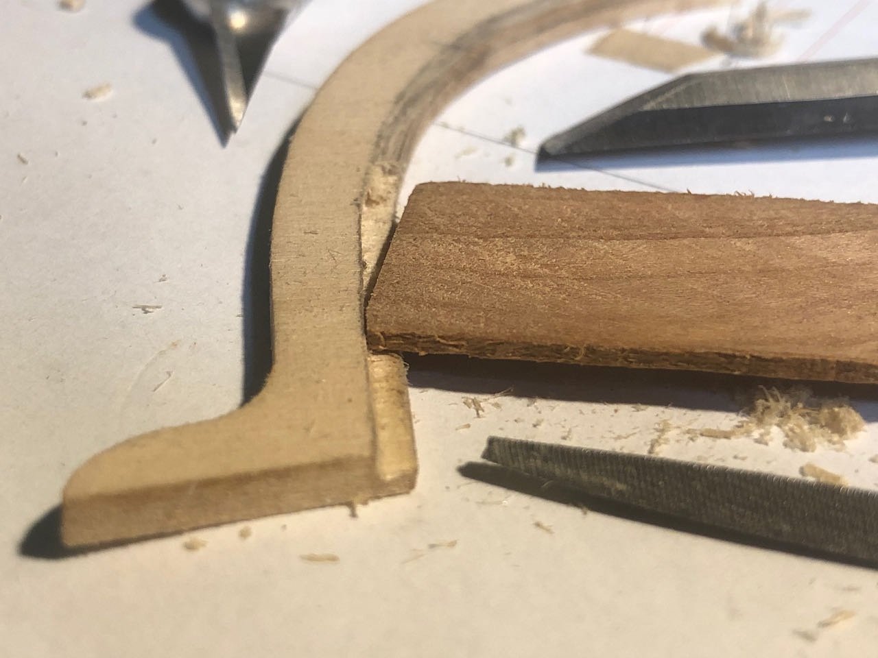
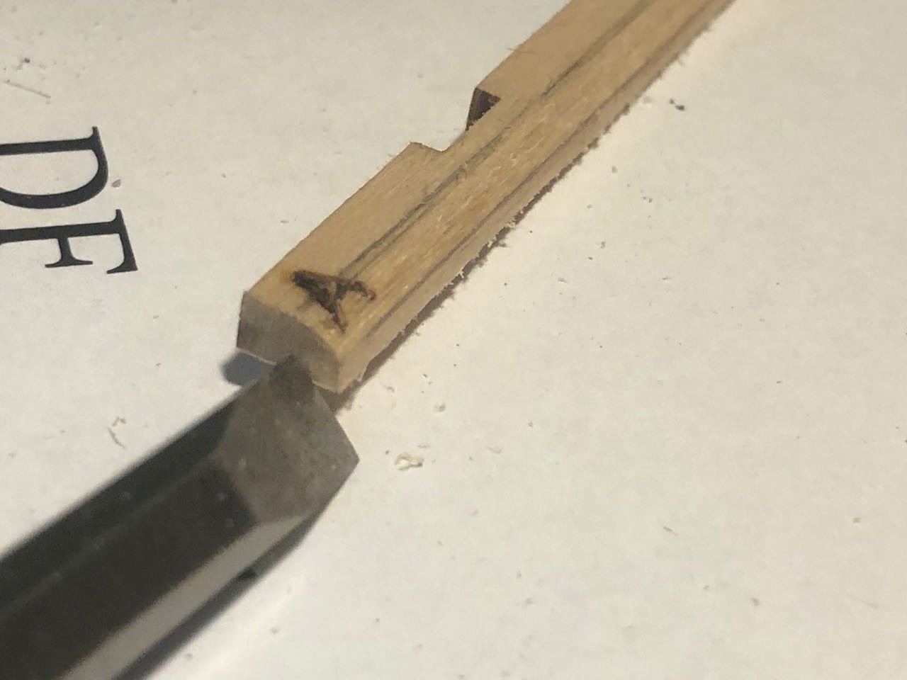
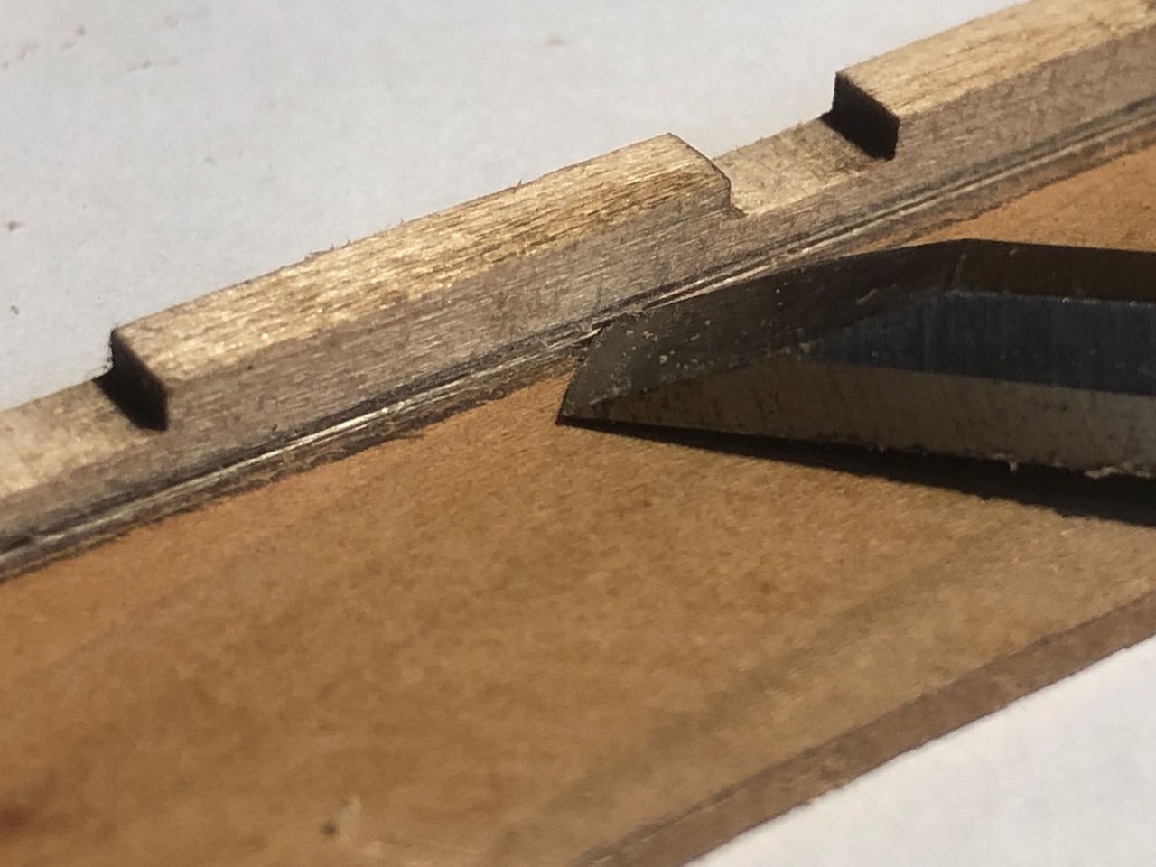
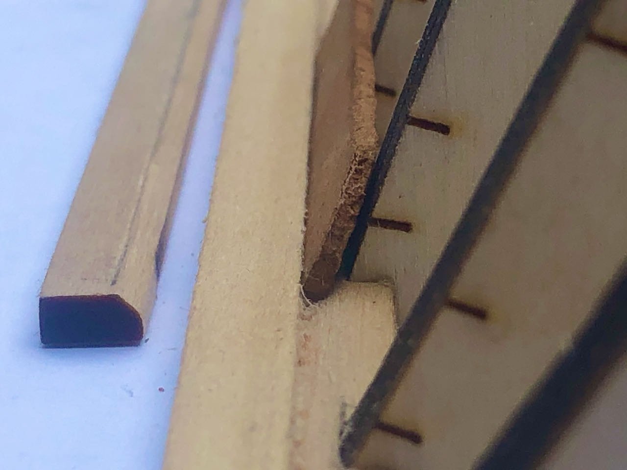
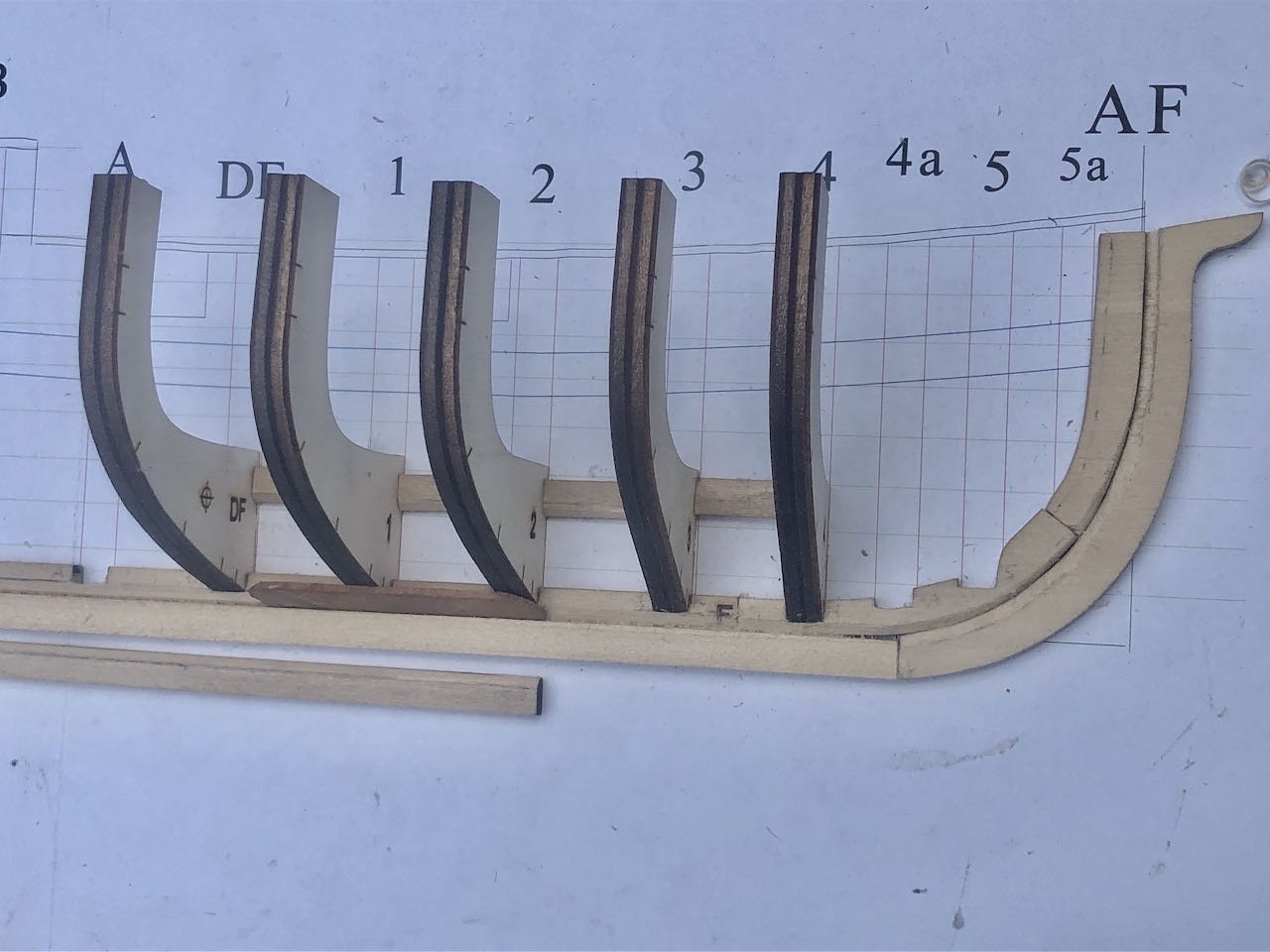
Further weekend progress. I ended changing a few things from the instructions to suit myself; that just seems to be a standard mode of operations for me. First, instead of gluing the plans to a building board and then gluing all the parts to the plan/board, I really wanted to keep the model separate and the plans clean. So I mounted the plans to a cutting mat using strong double-sided tape, and used the same to hold the keel parts in placing when gluing them together (but not to any backing). So far it's working fine. This kit uses a two-part keel/stem construction (outer stem, keel, and sternpost and inner stemson, keelson, and deadwood), as you can see in my very first photo (before I spammed the log with property photos). This is meant to make it easier to carve the rabbet. So I went ahead and carefully carved the 45º rabbet on the keel/keelson and stem/stemson pieces based on the thickness of my intended planking. To mark this line, I laid each piece against some planking and used a sharp chisel to scribe a line where the rabbet should start (this is more accurate than a pencil): I did this on two sides so there was a line guiding each side of the rabbet, then used pencil to darken these for visibility. I then used the chisel to cut the angle, finishing it with a sharp knife and sandpaper: At the stem, the rabbet gradually transitions from a 45º notch to a 90º mortise. This is delicate to cut because the soft plywood of the stem would be very easy to break. I did this slowly and carefully by scribing the outer curve with a sharp knife, then chiseling layer after layer away with gentle thrusts. I cleaned this up with square files. Here I'm testing the depth of the mortise with a piece of cherry planking: Next came the second instance in which I deviated from the instructions. The keelson has slots meant to accept the bulkheads. The kit intentionally leaves these shallow to strengthen this piece, and you're expected to deepen them down to the rabbet once this piece is glued to the build board. I decided it would be much easier to do this while the piece was loose, so deepened these using a razor saw on each side of the notch and then a chisel to remove the extra wood; a square file finished them up nicely. Below, a deepened slot at right, a slot with notches cut at center, and an unmodified slot at left. Sorry for the poor focus, iPhone photography doesn't like low-light closeups. Before I glued the stem/stemson/keel/keelson together, I did some test-fitting of bulkheads and planks, and really didn't like how the lower rabbet was performing. I thought I had cut it following instructions, but it felt way too large for my planks, leaving a clear divot between the keel and the lower edge of the garboard plank. I don't have a good photo of this because I just couldn't get the detail focused on and I was doing this in the evening. I also messed up and carved the rabbet all the way down the keel; this is supposed to stop at the deadwood as after that the whole geometry changes. I had even marked this spot, but obliviously chiseled right past it when the time came. So between those two things, I deviated from the instructions for a third time and used a very similarly dimensioned piece of basswood from my scrap pile to make a new keel. This one I didn't rabbet at all (leaving only the rabbet in the keelson). When I test-fit bulkheads and planks this way, my planking lay in the now-triangular rabbet just fine, and if anything the straight edge of the keel held it in place better. So I decided to go with that, knowing I could always carve out a faint rabbet later on the keel if I wanted. I don't know if that description makes sense, but in the photo below, you see the original keel with a 45º rabbet angling down to the right and the new keel without a rabbet; the latter is set against the keelson with its own 45º rabbet angling down to the left. Can you see how the plank sits nicely in its slot? When that original keel rabbet was there, the plank angled too far out and didn't sit well against the bulkhead (or there was an awkward divot between the surface of the keel and the beginning of the plank). I feel like this approach is a better fit and more secure, so I'm going with it. So after all that, I glued the stem/stemson/keel/keelson together (but NOT to the plans), then started adding bulkheads. These are also supposed to be glued to the plans, but I didn't want to do that. So I just glued them in at their lower tips and added lower spaces to help brace them, using various squares to get the orientation right. So far it's coming out nice and square with no issues. The photo below also gives another angle of the plank sitting nicely in my version of the rabbet. I'm pretty happy with these modifications and will move forward with carefully adding bulkheads. Thanks for reading!
.jpeg.69b28e9f796f46e3109aaae84a460800.jpeg)
-
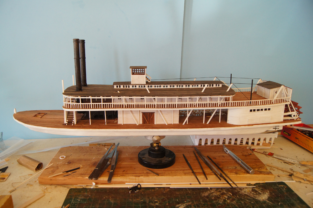
By "turnbuckles" and "masts", are you referring to the set of three posts that form a fan shape (one angled forward, one centrally vertical, one aft)? That's my impression from the accompanying photo. If so, those are AL's oddball version of what are properly called "hog chains". On real vessels, hogging (the hull sagging to fore and aft) was a huge problem as the hulls were long, thin, and very lightly built (none of the heavy timbers or cross-bracing of a sea-going vessel). The only way a steamboat could be functionally built this way was to introduce a set of iron rods forming a truss that held the hull in shape, not unlike a railroad bridge. These could be adjusted using turnbuckles threaded onto the rods (maybe that's where AL got its term?). Why they were called "chains" is not known. These were arched both along and across the hull on angled posts like the ones you've installed, though AL's design is pretty wacky.
-
Yeah, you can easily hide that behind deck detail. Anything like a rope coil, barrel, or crate would work fine and not be too out of place. Also, as it looks like the kit places some bitts right there, you could even build a thin planked and framed base below the bits that wouldn't look out of place, especially as this kit isn't a realistic depiction of an actual riverboat anyway.
- 109 replies
-
- 1
-
-
- Finished
- Artesania Latina
- (and 1 more)
-
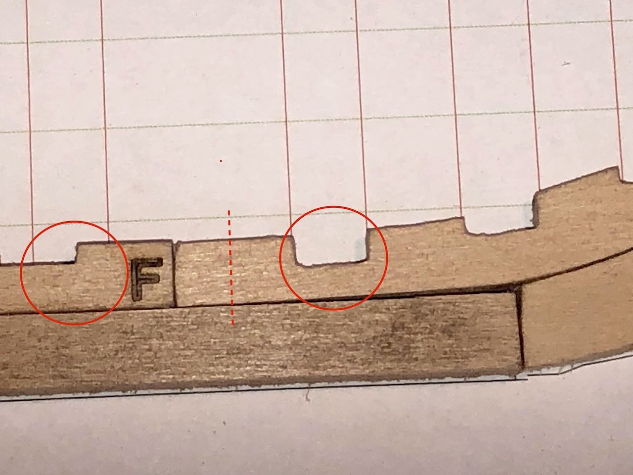
Back to the project, here's an issue I meant to bring up earlier but forgot. The supplied stemson seems to be too long: When I line up the stemson (upper right) with the bulkhead slots, its left end is too long, forcing the keelson (upper left) too far left and out of alignment with the bulkhead slots. The only way I can see to fix this is to cut off the end of the stemson (dotted line above). This isn't mentioned in either the kit instructions or the original build log, though an image from that log does appear to show the stemson overlapping the keelson before magically fitting; see the following two photos from that log (notice how the "F" on the keel is first obscured, then visible): I've read through 5 other logs, none of whom mentioned this (or I missed it if they did). I'm just going to go ahead and do this, as I can see no other way and can't see any possible harm after multiple test-fittings. But I mention it in case anyone else runs across this and is puzzled. The parts are otherwise very accurate, so this is a bit odd.
-
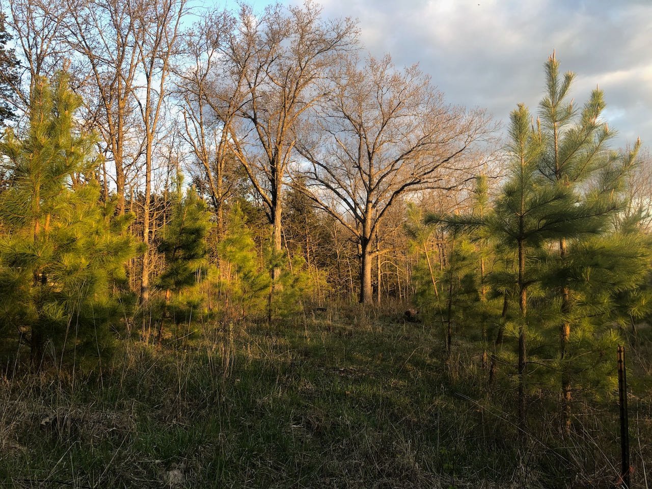
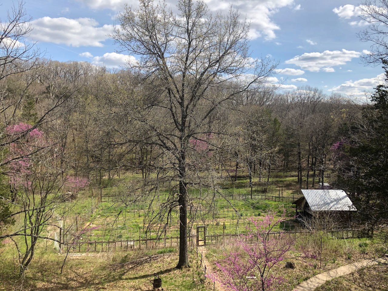
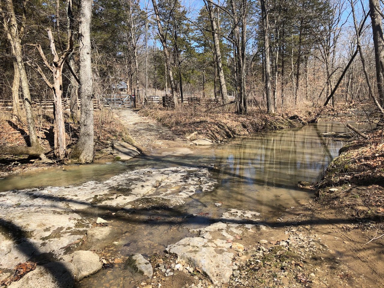
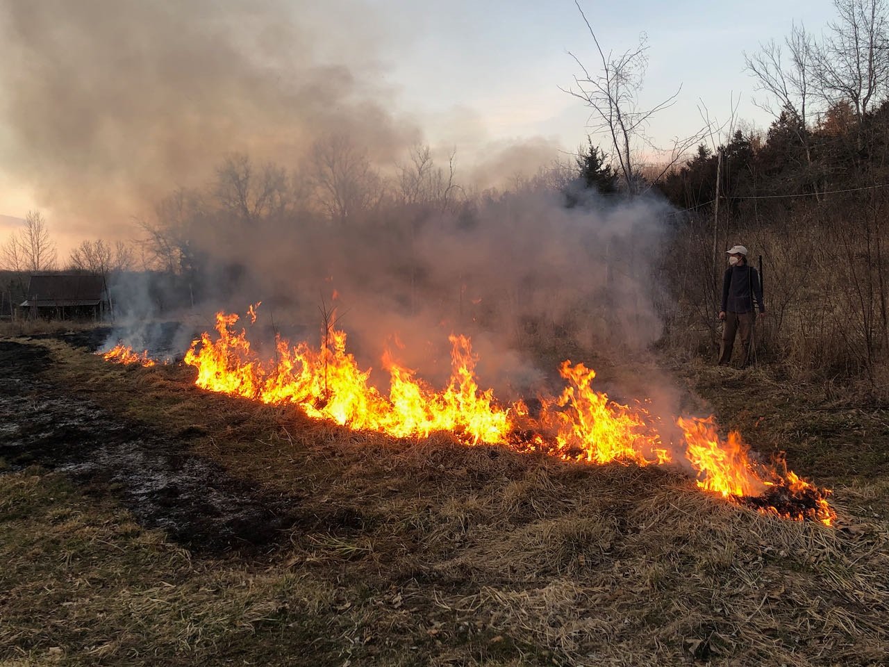
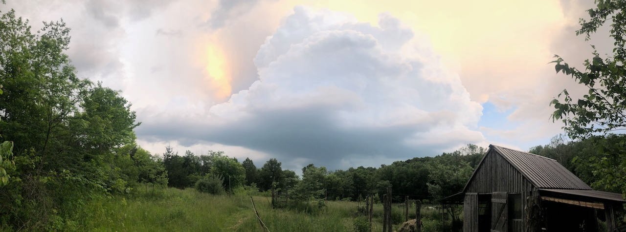
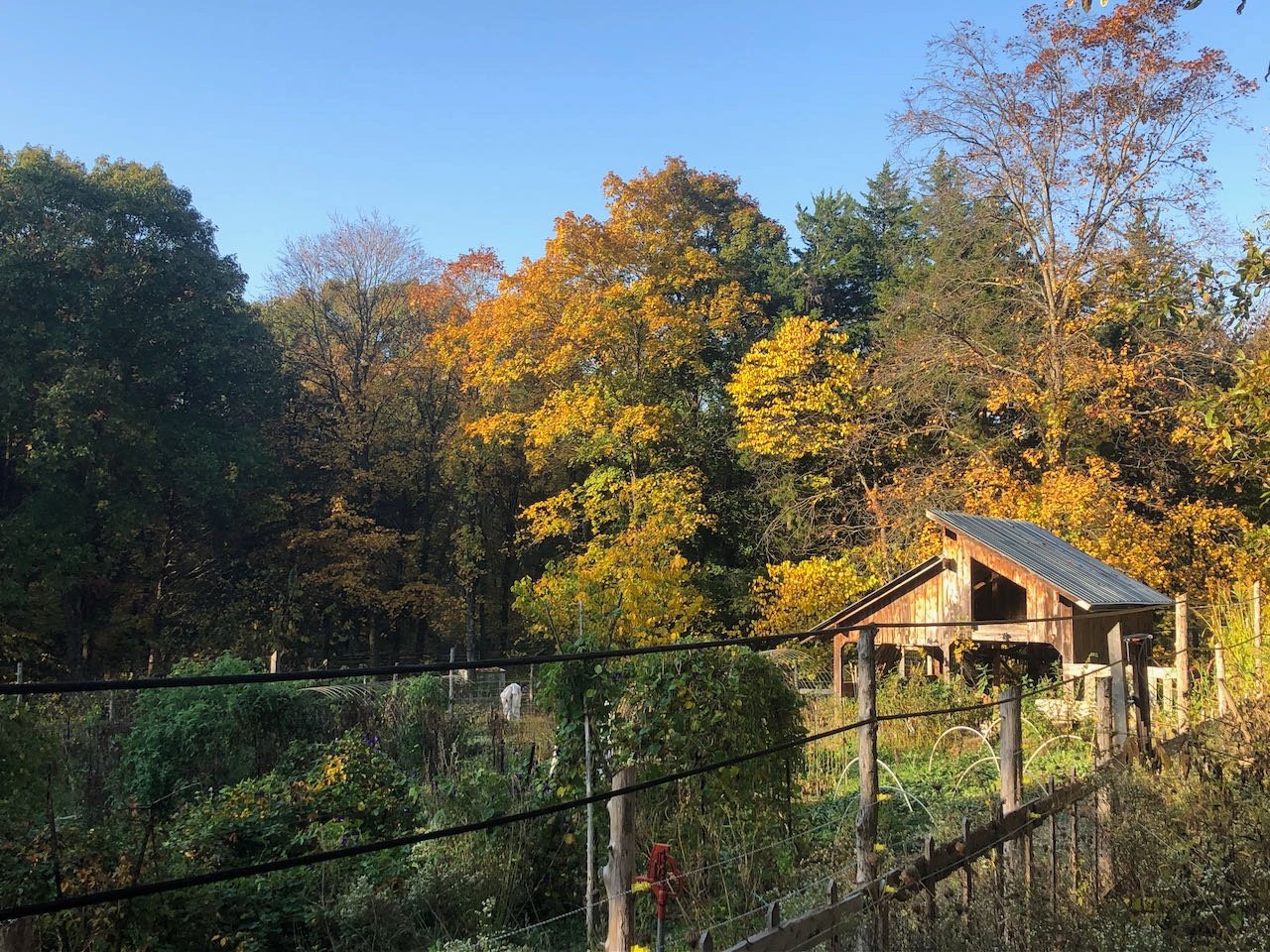
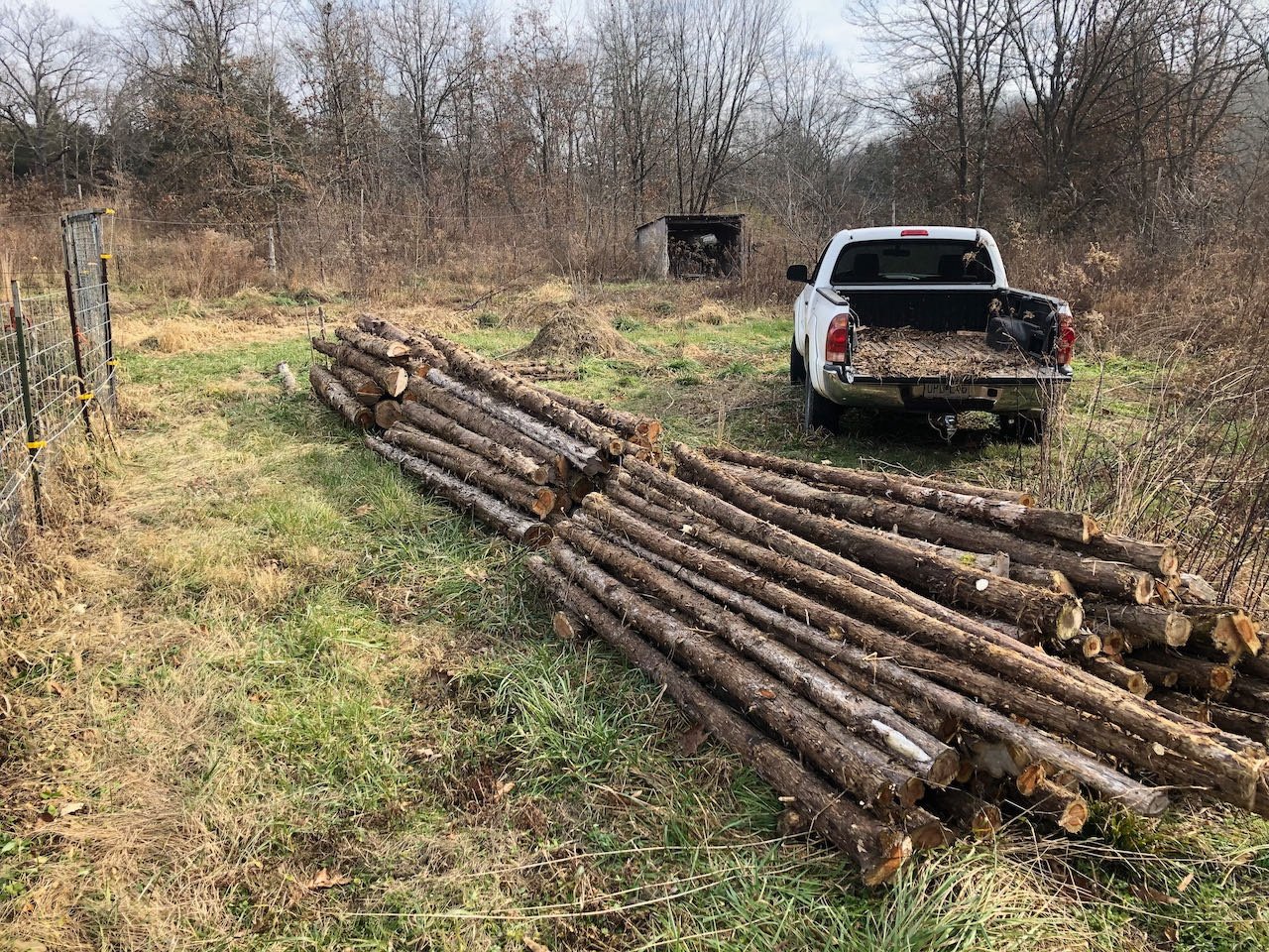
Well, Bob, you asked for it. I tried to select "a picture or two" and ended up with a photo essay. There's just a lot of diverse landscapes here and we've put a lot of work into improving the ecology here over the past 15 years. Others are welcome to skim right past this if desired, but it is relevant in the sense that landscape management here is a big part of my life and I'd like to tie my modeling into it. Spring in the creek-bottom garden below the house. I built the shed at right from wood cut and milled here; all fence wood is the same. The only way in is over a bedrock creek crossing. When the water's up, we stay home. We're surrounded in three sides by creeks, so during high water the only way out is a mile-long hike up and over a narrow drainage divide onto a neighbor's property and over to a connecting road. Another view of the garden and cedar shed. The maple trees in this bottom can give us about a gallon of syrup in a good year: A couple shots of forest in summer and winter. Our region is dominated by oak/hickory stands, with other hardwoods mixed in, and sycamores and cottonwoods common along creek bottoms. Cedars take over any open area that isn't kept mowed, grazed, or burned. An oak-hickory fencerow stand, in front of which is one of two pine plantations we've started. Thunderstorm over pasture. I build the barn at right for our small dairy goat herd, also of on-farm wood. I love being able to tie buildings together with 16' heartwood beams, you just can't buy wood like that! Controlled burning to used to manage pastures and prairie plantings: Hauling smaller cedar logs for future fencing work. Bigger logs get milled and used or sold. Overall, we put a lot of work into managing our woodland and pastures for healthier trees and ecosystem restoration. This was a pretty degraded landscape when we bought it 15 years ago, due to overfarming followed by neglect, and we've been bringing it back to life. Some upland pasture areas literally had bare soil where nothing grew, they were so degraded; now they have ground cover and an increasing mix of native wildflowers. Forests are being thinned and healthy trees selected for and given room to grow. My stock of modeling wood basically just comes from castoffs naturally resulting from timber management and firewood cutting, as we inevitably need to thin young or dying trees. I also have some more obscure stuff on hand, like redbud, and various fruitwood from our orchard, that I want to start playing with. And now back to the project at hand!


- 36 replies
-
- 14
-
-
-

-
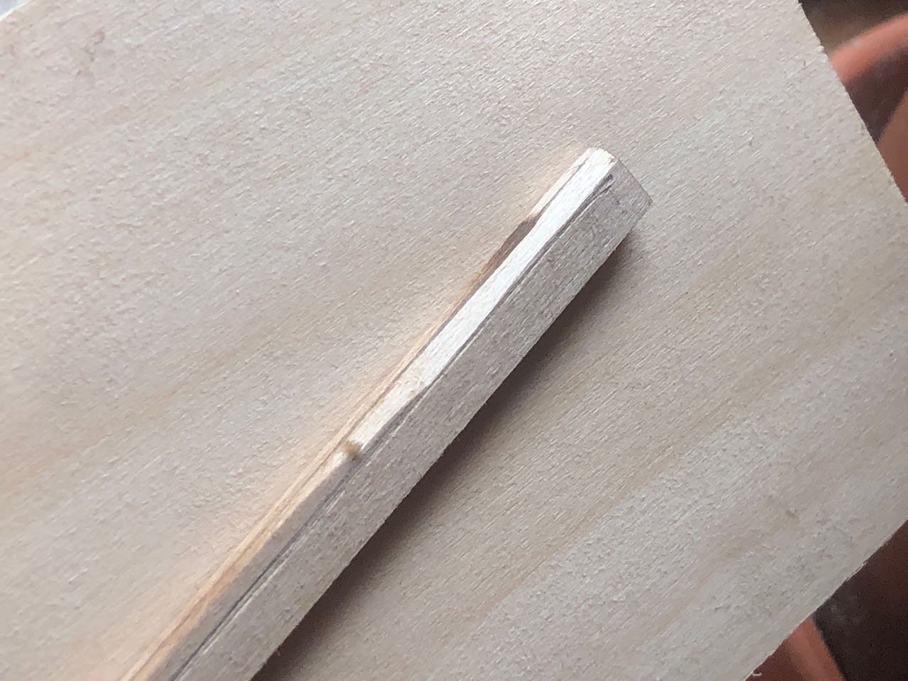
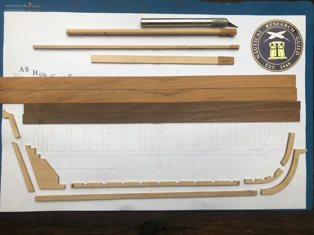
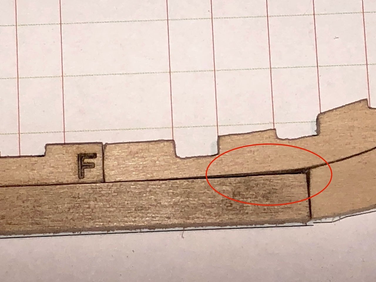
And here's the first steps. I removed all the keel parts and carefully sanded them to remove laser char, then test-fit them on the plans. I also milled a few test pieces of planking stock, intentionally wider than the actual planking to allow for spiling. The image below shows the keel pieces, basic knife and sanding sticks, and cherry/walnut strips laid out on the plans. After two very large builds, it's really nice to be working on such a compact project. I immediately made a small mistake. The fore end of the keel has a slight curve upward to fit into the beginning of the curve of the stem. I accidentally sanded this off, as it's pretty subtle and the rest of the long piece is straight and flat, so I just worked down the whole thing on a flat surface. So when all the pieces are test-fit together, there's a clear gap (circled in red below): Oops. I don't think it really matters, though, the rabbet runs through here and it'll be completely hidden. It might weaken the joint slightly, and maybe I'll use some filler when this gets glued together, but overall it doesn't seem like a major issue. A good reminder to be careful and attentive, though.
-
Thanks again to all of you. For those who might be interested, I've started my next project, the NRG 18th century merchantman half-hull planking kit. While this has been done many times, I'm adding a twist by intending to do all the planking using wood I harvested and milled here on my rural property, primarily cherry, walnut, and maple. I hope that adds to the interest, but regardless, I'm glad you came along for the ride on this longship.
-
This kit was developed by the Nautical Research Guild to teach or improve members' hull-planking skills. As a moderately skilled builder, I decided it would be a good project to force myself to learn best practices and possibly correct poor practices I may have developed. Plus, it seems simpler and more relaxing than my last few builds! Here's the NRG's vision of the final project: There are many build logs for this already, but I intend to add my own twist by doing the planking using wood I've harvested and milled myself from my rural property, where I do a lot of timber management. This is the direction I'd like to take my modeling overall, so this will be a good early test of the goal. I have well-cured cherry, walnut, and maple billets on hand and think a mix of those could look really nice on this hull. Right now my idea is to use cherry below the wale, walnut for the wale, and maple above it. We'll see what happens. Hopefully this is of interest to a few people, but regardless of attendance, I've learned that keeping a build log is a good way to keep myself engaged and organized.
- 36 replies
-
- 11
-
-
Paul, very nice work on this little model. To answer an earlier question, I cannot figure out what the little grating at the stern is for, either. You also wondered why this model seemed unpopular. I assume you mean on this forum, as we have no way of knowing what sales figures are overall. As this is an English-language forum dominated by Americans, British, Australians, and so on, I suspect that Spanish and Mediterranean vessels are somewhat less familiar and thus less popular in this context. I would not be surprised if Spanish or Italian forums had many more of these, and fewer Constitutions, Victories, whaleboats, and so on.
-
Trireme Olympias - wonderful footage
Cathead replied to Louie da fly's topic in Nautical/Naval History
Fantastic video, thanks for sharing. I sent it to my brother, who's long been interested in ancient Greek history.- 4 replies
-
- 2
-
-
- ancient Greece
- galley
- (and 3 more)
-
I also love creating/upgrading details from kits' basic state, so very much recognized the impulse at work here!
- 33 replies
-
- 1
-
-
- Artesania Latina
- Whaleboat
- (and 3 more)
-
I think it's the right choice. The dark red provides a clear transition between the black outer shell and the bright raw wood that's visually appealing and helps the viewer instinctively recognize the difference.
-
I think black would be entirely reasonable for the wheels and axles and would give a nice contrast the carriage and a nice symmetry to the guns themselves.
-
A frustrating situation to be sure. Best wishes for resolving it and being able to return to this incredibly meaningful project.
-
You're doing a really nice job on this, I hope you keep updating the log.
-
I'm working on catching up on logs I hadn't found yet. I'd say there's interest, you have a set of likes on each post. Sometimes folks just don't comment when they don't have more to say than "good job" so as not to clutter up the log. I think your work looks great and would like to see more.
-
Golden Hind by BobL - OcCre - 1:85
Cathead replied to BobL's topic in - Kit build logs for subjects built from 1501 - 1750
Any further progress?