Cathead
-
Posts
3,538 -
Joined
-
Last visited
Content Type
Profiles
Forums
Gallery
Events
Everything posted by Cathead
-
 Looks beautiful. I think it's safe to say the Greeks knew about caulking, there's evidence of Bronze-age caulking even in the backwaters of Britain (using things like moss and wool if I remember correctly). Maybe not the Age of Sail kind, but there're lots of ways to do it, and you pretty much can't build a planked craft without it.
- 62 replies
-
- 3
-

-
- amati
- greek bireme
- (and 1 more)
-
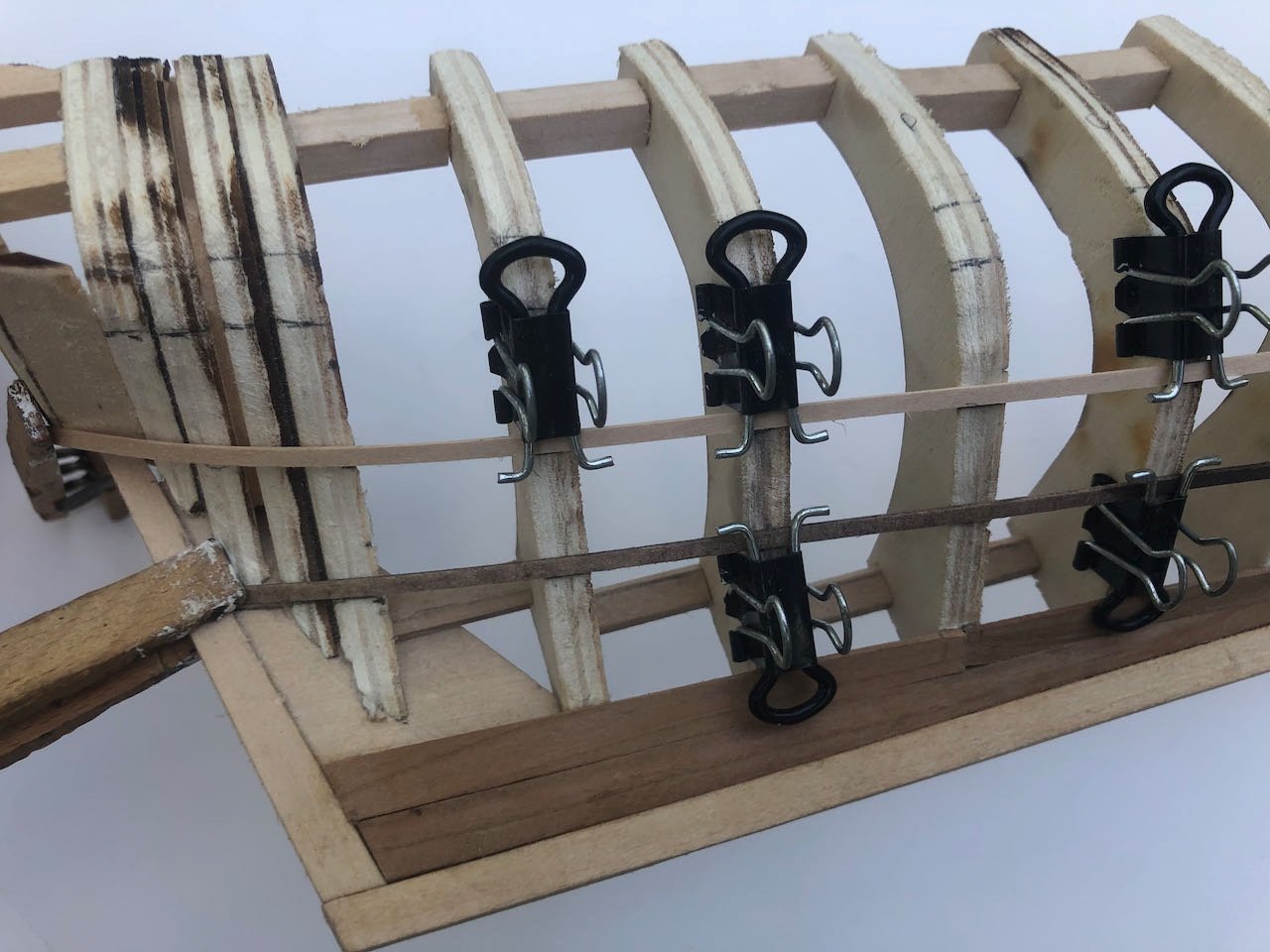
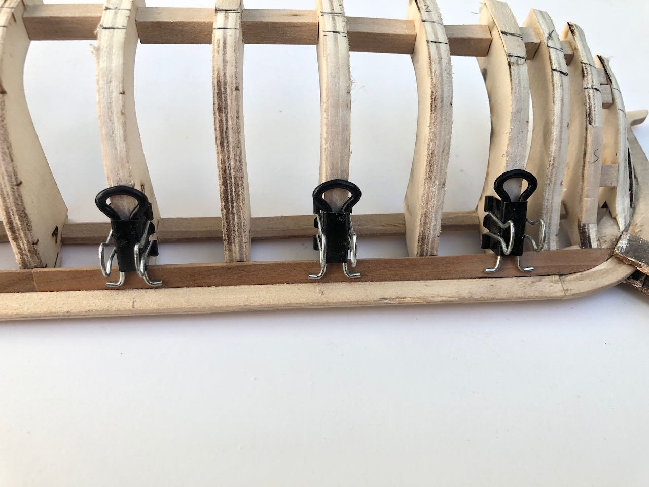
Wish I had advice on the rigging. I've used clamps to help maintain tension, as it looks like you did, too.
-
Since you mentioned it, the word you're seeking for "steering handle" is "tiller". Also, the mechanism for raising and lowering the anchor would be a "windlass". Nice work, the model's very attractive so far.
-
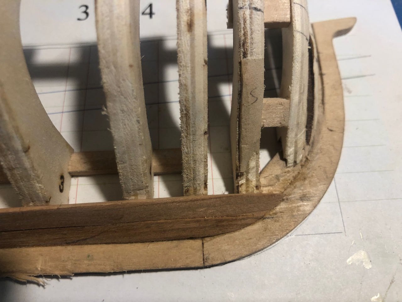
I've been working on laying out planking belts and could use some advice. The instructions call for dividing the hull into three belts between the wale and the garboard strake, and here's my first attempt. Note that the strips make the central belt look narrower than it really is because I'm measuring from their lower edge (so the middle belt includes the strip's width). I've measured them and they're all three equal amidships. Stern: Bow: I've never done this before and am having difficulty envisioning what's correct, especially at the bow. My sense is that the run of the planking should look pretty horizontal when viewed from the side, no curving up or down as the hull changes shape. I'm having trouble comparing this with the images shown in the instructions and log. I'd be grateful for any advice from @tlevine or any other experienced folk. Thanks!
-
The irony is there's both in our medicine cabinet, since my wife makes very effective vodka-based herbal tinctures for sleep. Chamomile and ashwagandha are very effective, only a small dropper's worth needed.
-
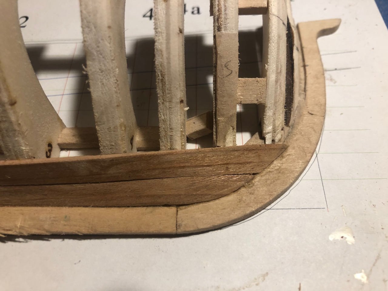
During the week, I had finished installing the broad strake (the next one up from the lower-most garboard). But a little demon in the back of my mind kept telling me it wasn't right. At the bow, both planks ended up curving upward and creating the "smiley-face" effect that the instructions specifically warn against. It wasn't really obvious to me until after I saw both strakes in place, but then I couldn't unsee it, and knew I had to fix it. After watching @tlevine's NRG presentation this morning on improving ones' models, which included the specific exhortation to fix things you know are wrong so you don't regret them forever, I did so. Here are the original planks at the bow: Not only can you see a strong upward curve, look at where each plank ends relative to the horizontal lines extending off to the right on the plans. The top of my garboard meets the first line, while the top of my broad strake meets the second one. Now look at how this is supposed to be, from the demonstration build log: Notice how BOTH strakes fit into the space below the first horizontal line, and the flow of the planking is much more horizontal when viewed from the side. I don't know how I let it get so off, but I did. So out came the alcohol (for the glue, though I considered my own emotional needs) and a sharp chisel blade. I removed the forward broad-strake plank and then carefully carved the top of the garboard strake down to a better alignment: I made a mess of the rabbet in the process, especially carving out all the bits of glue-stuck wood in there, but it doesn't matter in the end. I then reshaped a new plank that looks much better. Ironically, this was easier than expected because I had gone through several attempts at shaping this plank in the first place, and one of my discards ended up being just right for the new plank with some more shaping: It's still a bit higher than it's "supposed" to be but I think it's good enough, and I'll pay more attention from now on. It's interesting working with the cherry, which is stiffer to bend but also more forgiving to carve and sand than the super-soft basswood I'm more used to. Next up, laying out the planking belts.
.jpeg.48528e9559e0f369ec73a7ba9bf571e4.jpeg)
-
Your idea is great, but is there any reason they need to be circles? Squares would be much easier to make and seem like they'd grip just as well since the essential point is the surface, not the shape of the edge.
-
For what it's worth, "chimney" is the correct term for what would otherwise be called "smokestacks" on a riverboat. Just one of those language quirks; that's what they called them.
-
This is just a guess, and hard to describe in writing, but I think the thread on the back side is being tucked under itself before heading off to the next loop around the spar/sail, and that's what's letting it get drawn up along the spar and out of the way rather than creating the diagonal that you have. Looking closely at the instruction photo you posted, I can see that each section of thread running along the spar does a little jog under each loop that looks like it's tucked under and drawn tight. So consider the following actions. Starting at the end of the spar, from left to right, for each loop: - Thread gets run to the next loop - Thread goes over the spar, down through the hole in the sail, out the other side, and back up to the spar. - Now, thread gets tucked under itself, from left to right, then run toward the next loop. This ought to pull the previous one tight against the spar and draw the overlap up to the spar instead of across the sail. I tried this in my mind and it worked. Don't know if that's clear, or even right (could be mistaken). If you want, I can make a quick test case with a few photos to show what I mean.
- 160 replies
-
- 2
-
-
- Model Shipways
- norwegian sailing pram
- (and 1 more)
-
Nice job so far! Very cool that you're using local wood, A. angustifolia looks similar to the related Araucaria species I've seen in Chile. In tree form, anyway.
- 21 replies
-
- 1
-
-
- Swift
- Artesania Latina
- (and 2 more)
-
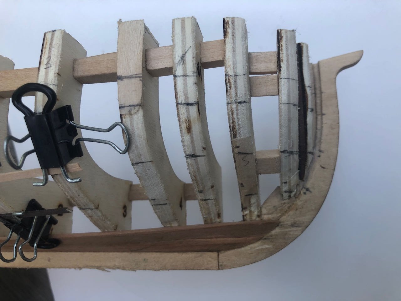
Garboard strake is shaped and attached. This went smoothly following the directions. Basically, I marked off a scale 12" up from the rabbet on the frames in the center of the vessel, a scale 14:" at the stem and stern, then used a thin batten to project the line the rest of the way. Then I cut out a paper template and used that to cut the planks from my strip of milled cherry. Planks cut prior to bending: Each plank was then soaked and clamped on to take the necessary bend. I used a hot planking iron to fix the bend in place, moving my clamps one at a time to get full coverage: And here is the garboard strake glued on: The closeup photos show that I've been having some trouble with the softer keel woods, both the plywood stem and sternpost from the kit and the basswood I used to replace the lower keel. They're damaging easily. I intended to sand the damage done once the planking is done and see what it looks like then. Camera closeups are also great at accentuating such things when they'll be hardly noticeable on the finished product. This honestly went more smoothly than I expected and makes me look forward to continuing on. Can't wait to see this really start to take shape.

- 36 replies
-
- 10
-
-

-
What a neat and worthwhile prototype! I look forward to seeing this project come together.
-
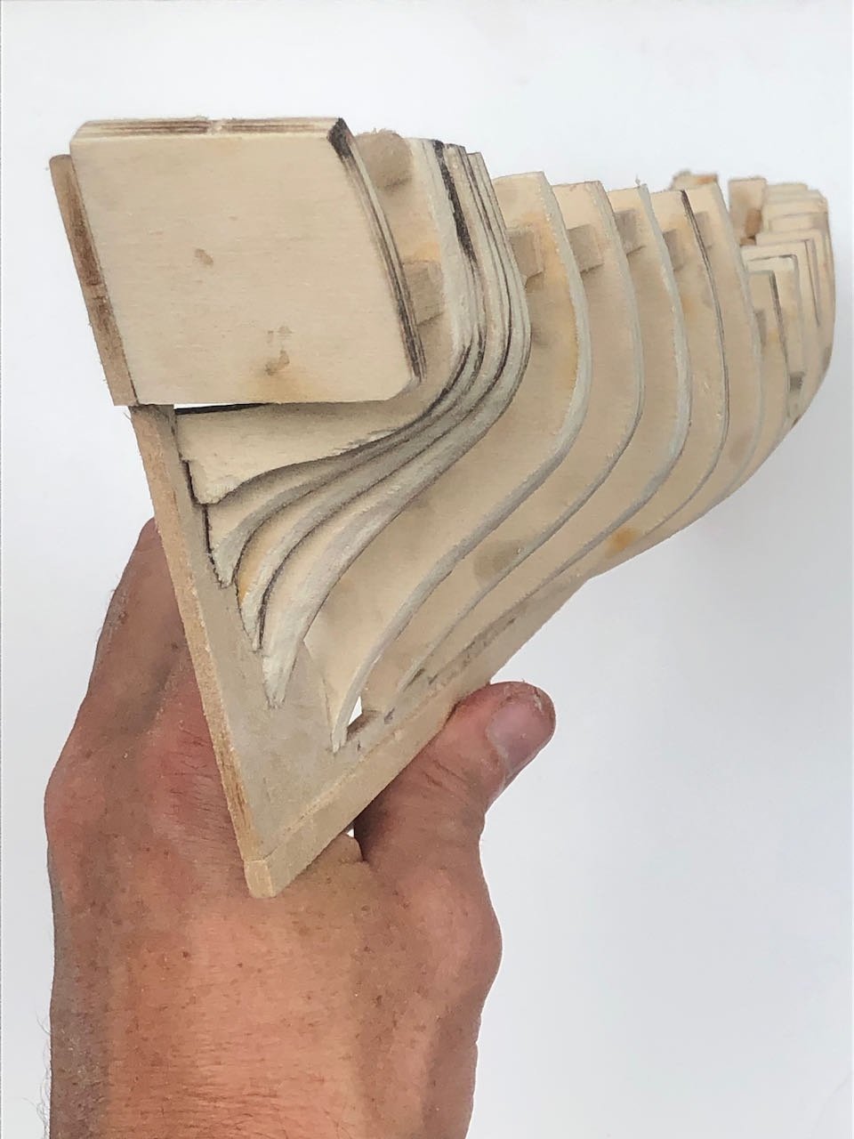
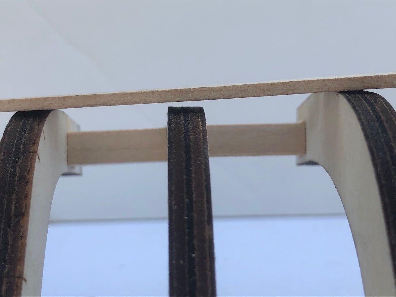
So far I've found it very helpful to be able to remove the framing, it let me reach a variety of different angles while fairing that I otherwise could not have achieved. I was also able to better stabilize individual frames while working, by reaching in from behind, which I found important because the framework overall isn't very well supported from the back and can twist easily under pressure (unlike a frame with solid bulkheads connected to a longitudinal sheet). I suppose one could achieve this by gluing some additional supports between the back of the frames and the build board. I can see the value of either approach but I haven't regretted mine yet.
-
I can definitely appreciate the fenders. As a young'un in Western NY, I enjoyed watching lake ships pass through the canals and locks bypassing Niagara Falls. Seemed like there was only a few inches clearance on either side, and in those pre-9/11 days, you could walk right up to the canal-side and touch the ship as it went by.
-
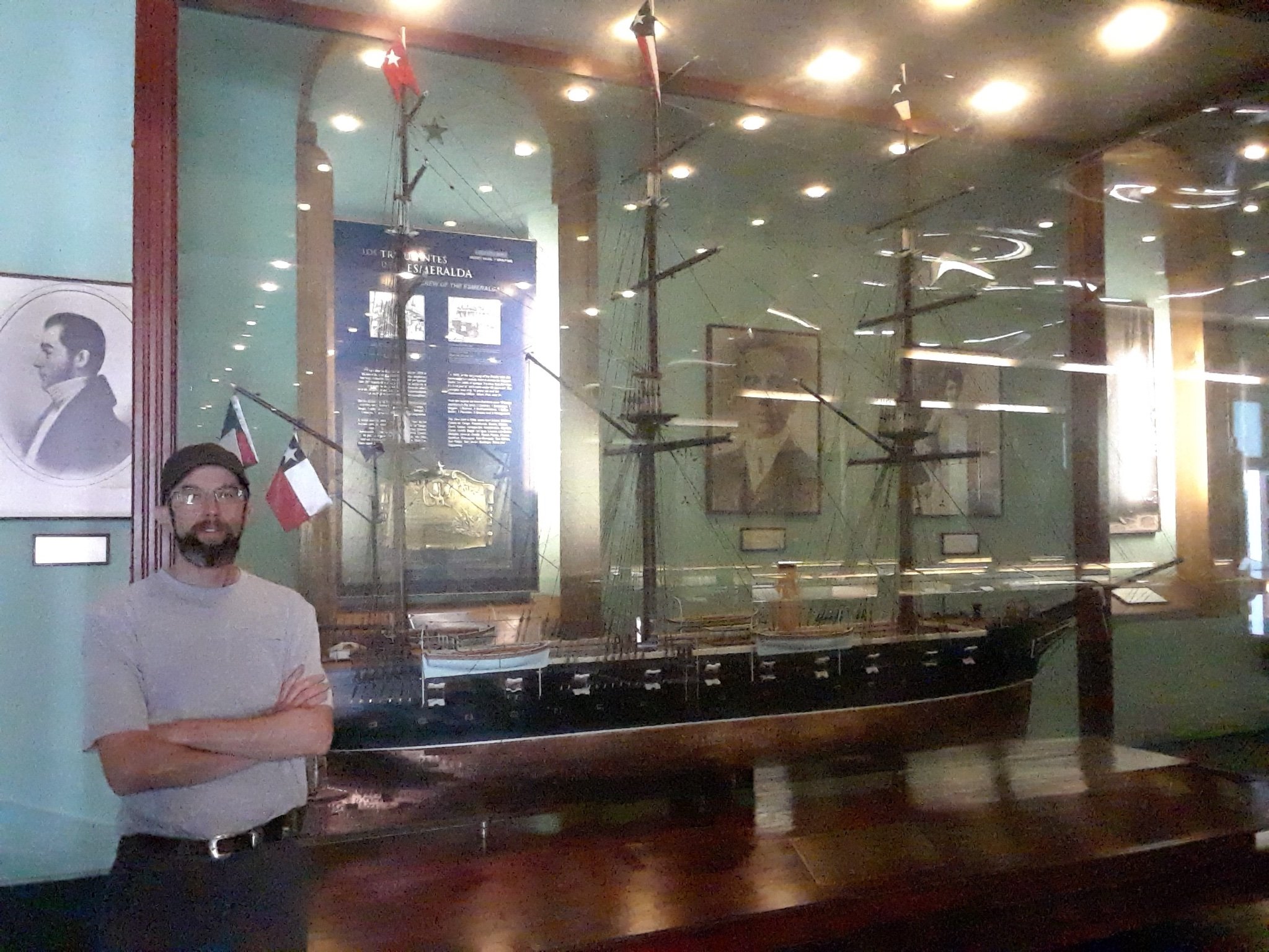
I was thinking of the vessel captained by the famous Arturo Prat at the 1879 Battle of Iquique, seen here in 1:20 glory at the Museo Marítimo Nacional in Valparaíso (me for scale). Or perhaps one of various vessels from the War of Independence. As you say, the modern Esmerelda has a somewhat controversial history. But I should not derail your thread any longer. I look forward to learning more about her Mexican equivalent!

- 17 replies
-
- 3
-
-
- Cuauhtemoc
- Mexico
- (and 3 more)
-
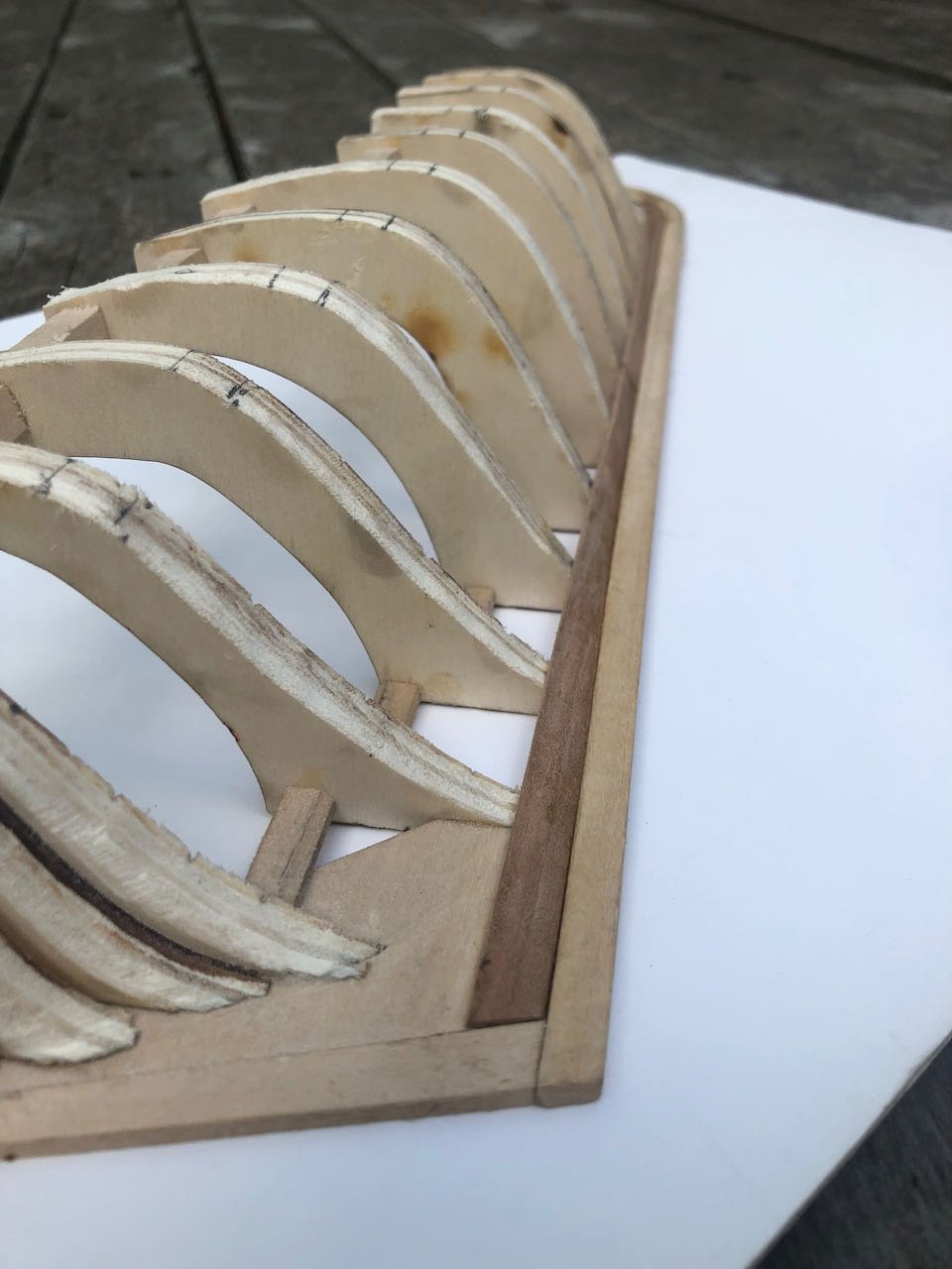
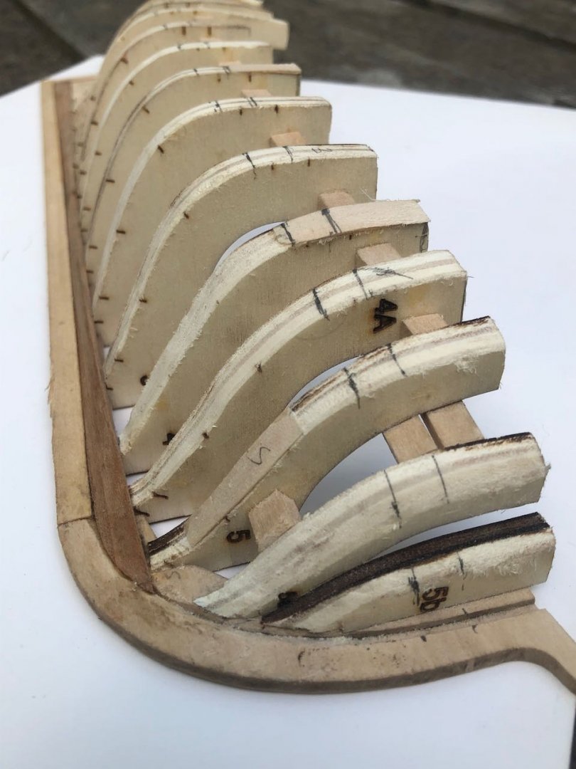
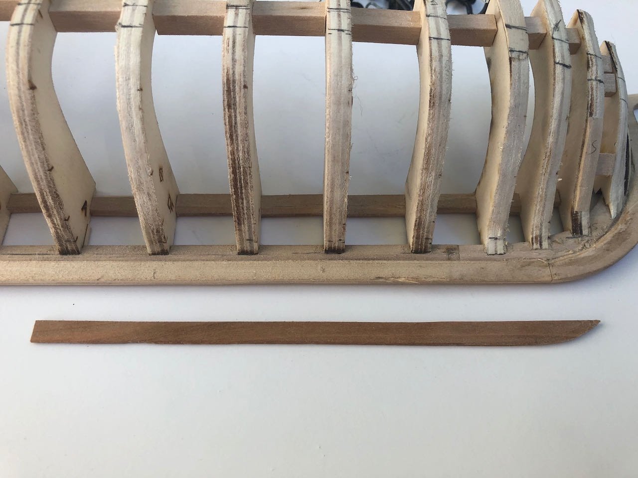
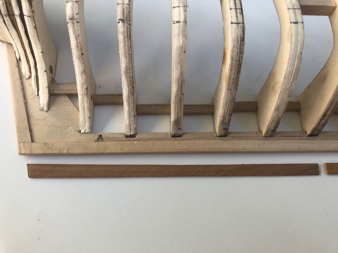
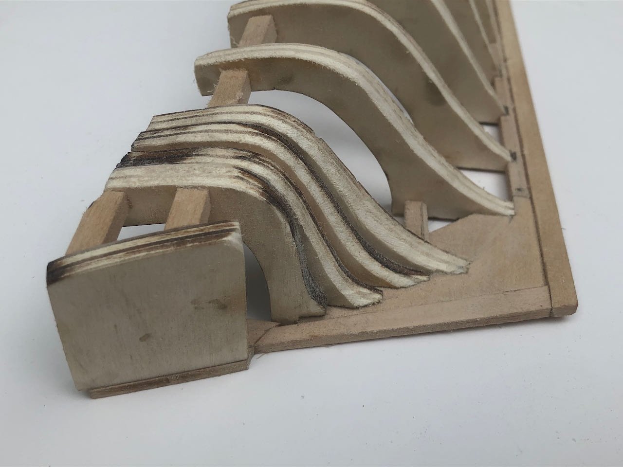
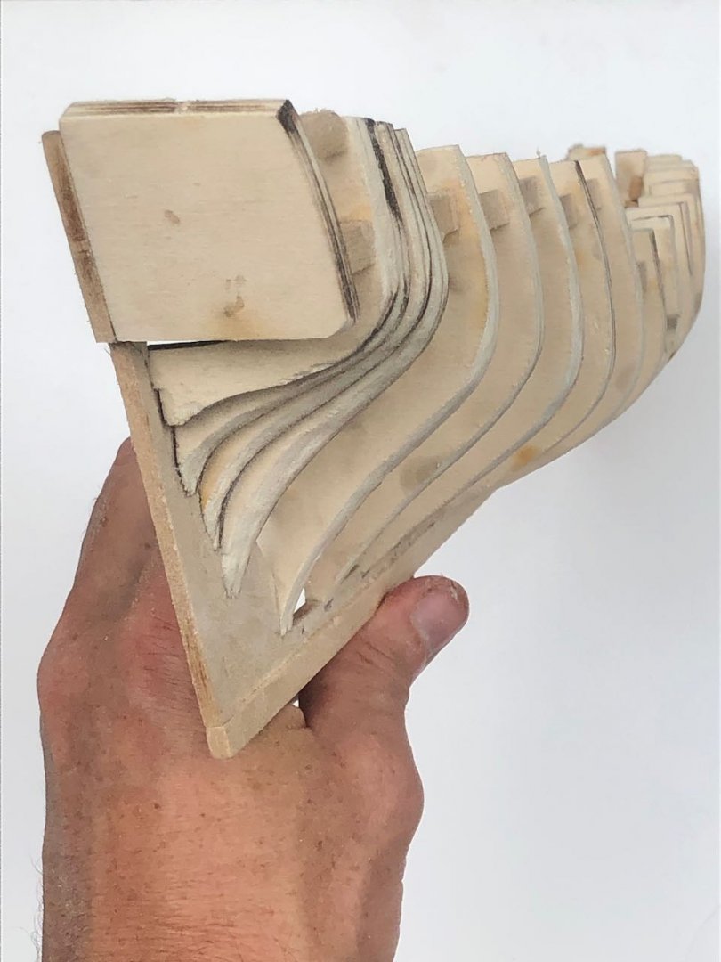
Fairing is complete. It was pretty straightforward; a lot of material to be removed and some shimming to be done, but I feel reasonably comfortable with the result. I ran thin battens all over it to check. I can always do small-scale revisions as planking progresses, adding a tiny shim or carving a bit away if needed. One nice thing about a half-hull is you don't have to worry about symmetry between both sides! Bow views: Stern views: Overall views: So far this is all pretty dull. I'm looking forward to starting the actual planking, when I find out if I'm crazy for trying to use my own wood...
-
Cool prototype, this looks to be a very interesting project. A Chilean naval vessel is on my maybe-someday list, so following this can be a stand-in for now.
- 17 replies
-
- 1
-
-
- Cuauhtemoc
- Mexico
- (and 3 more)
-
I think they're quite good in context.
-
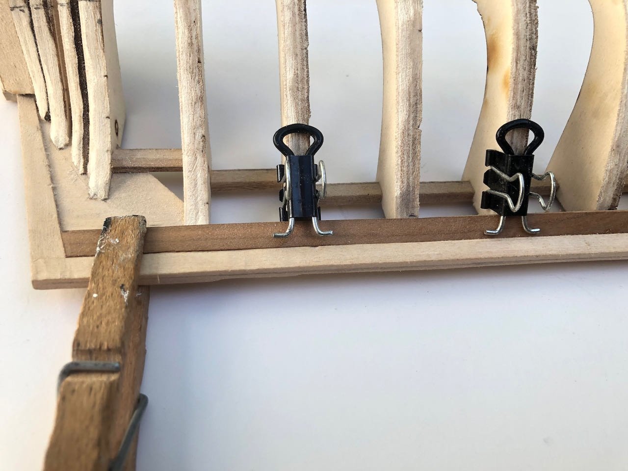
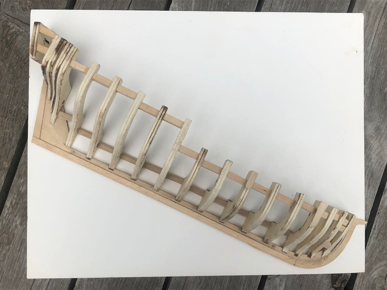
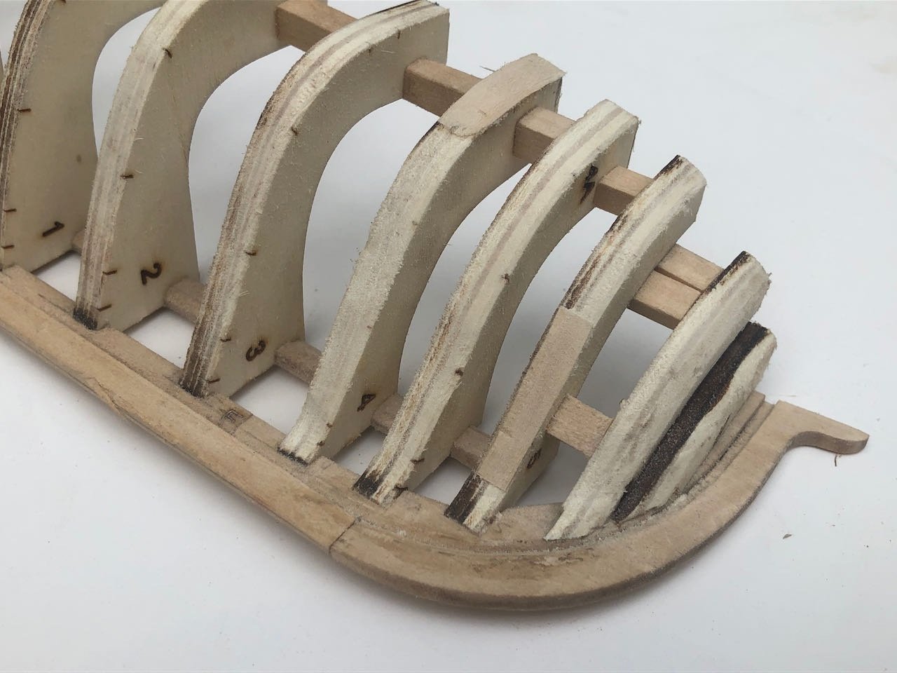
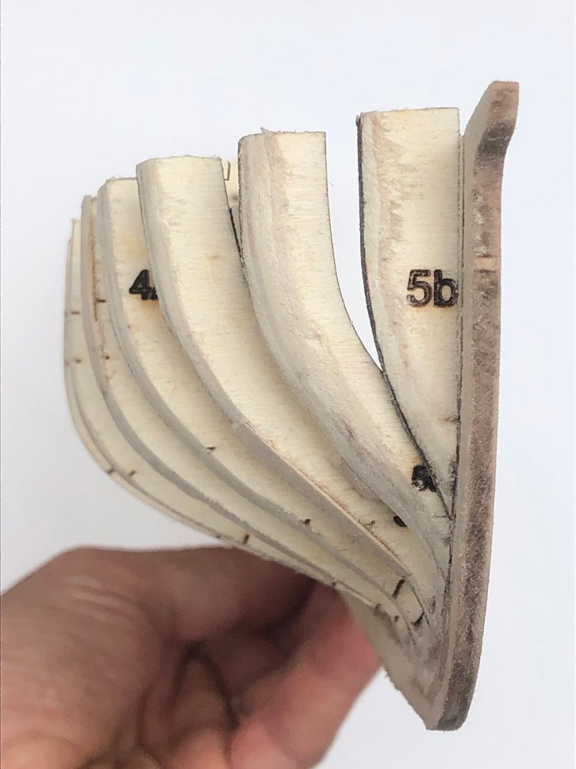
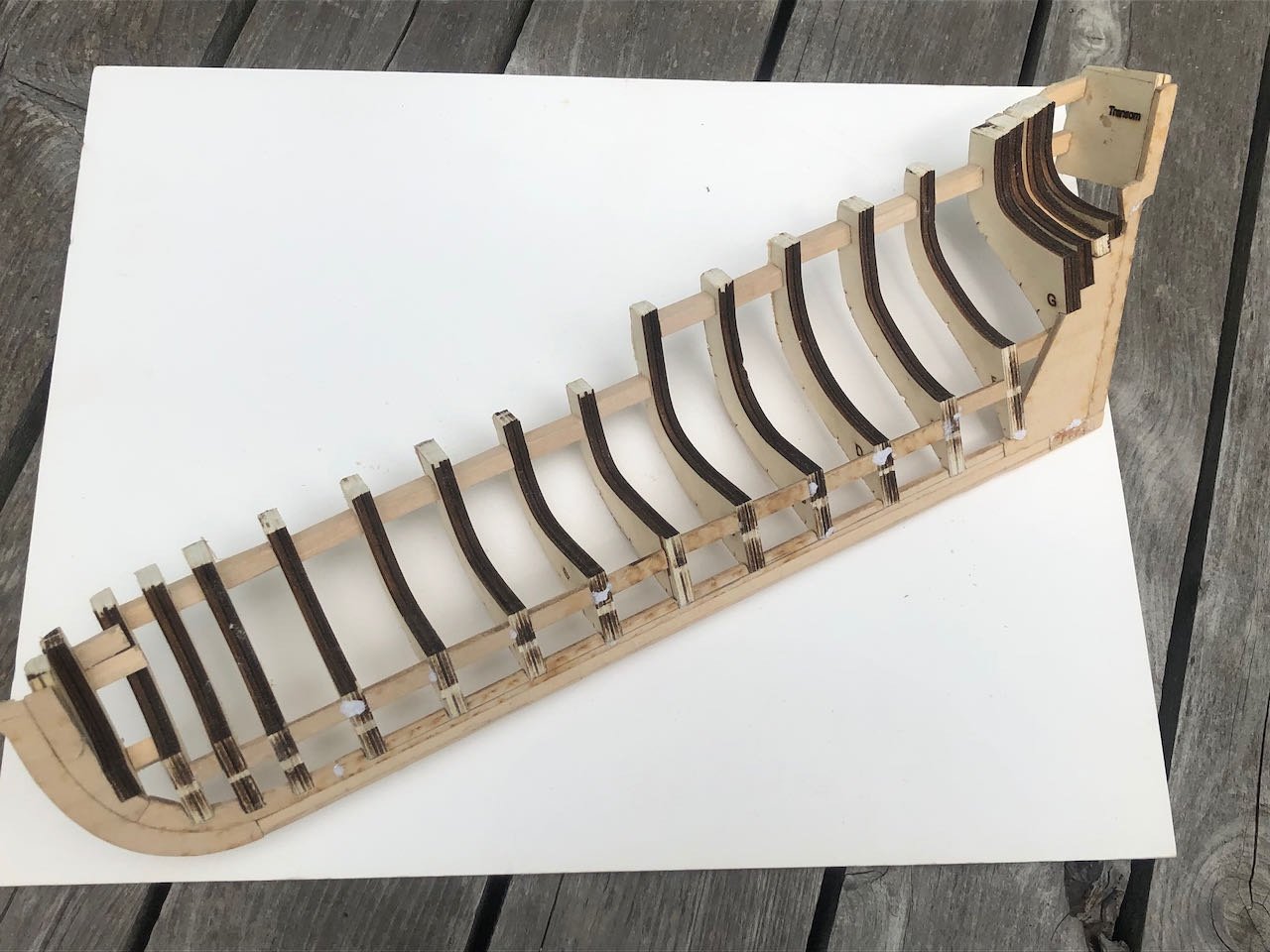
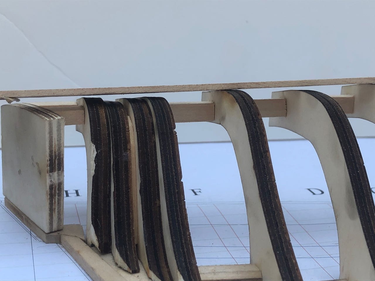
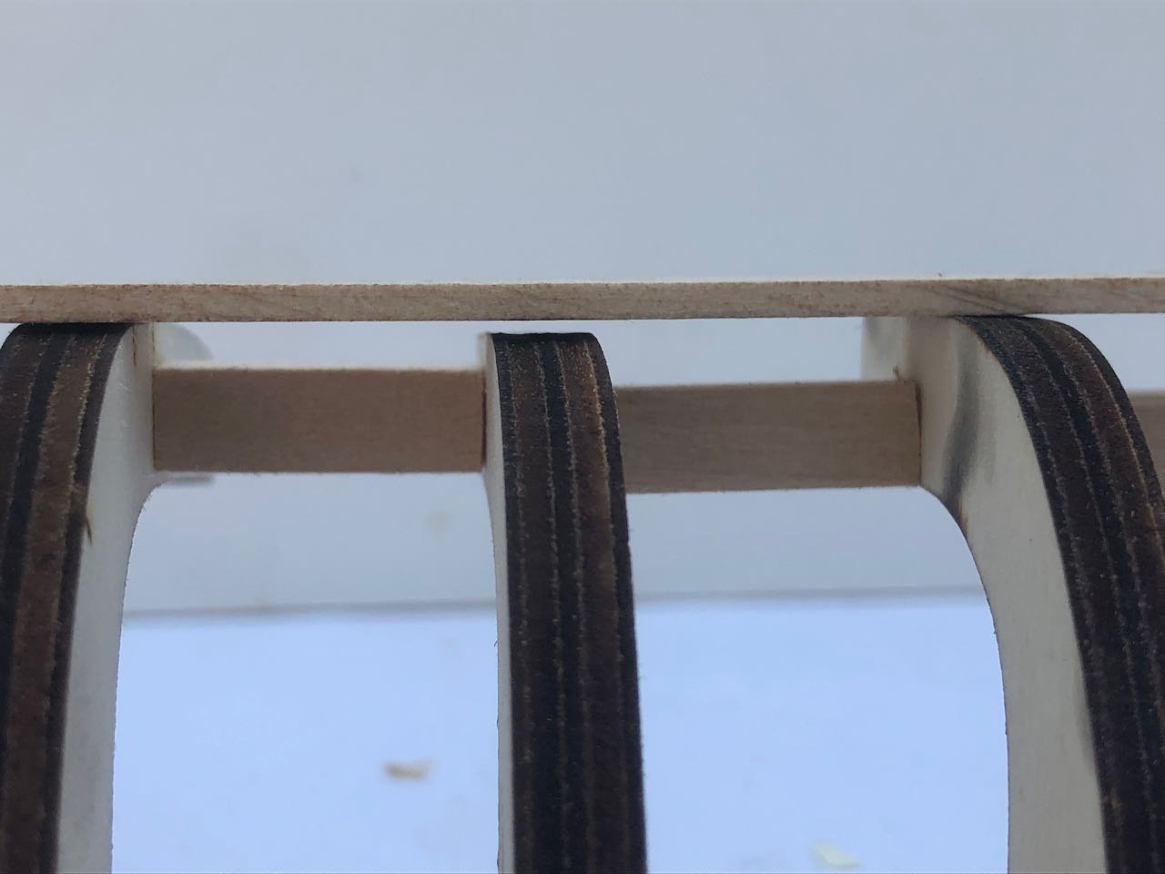
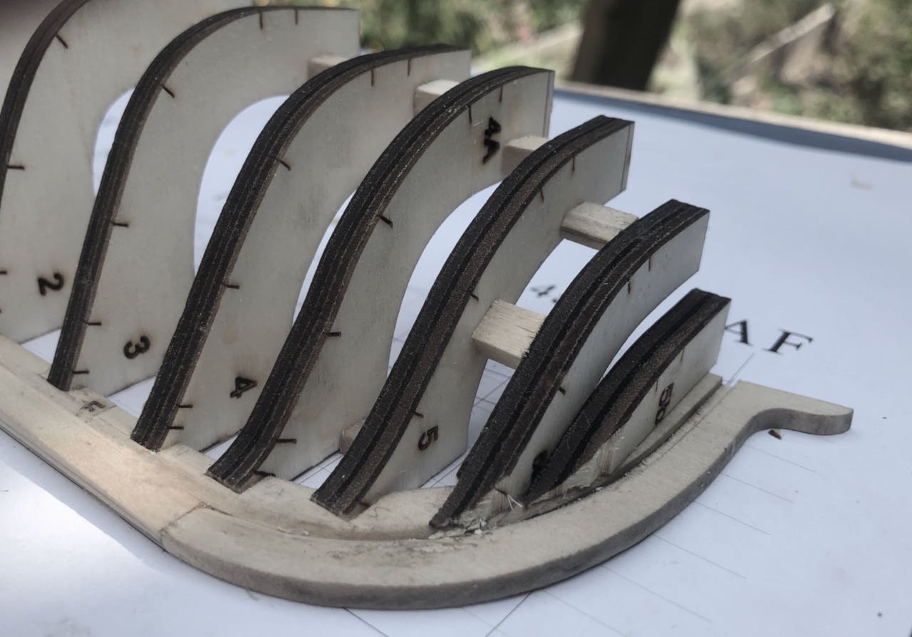
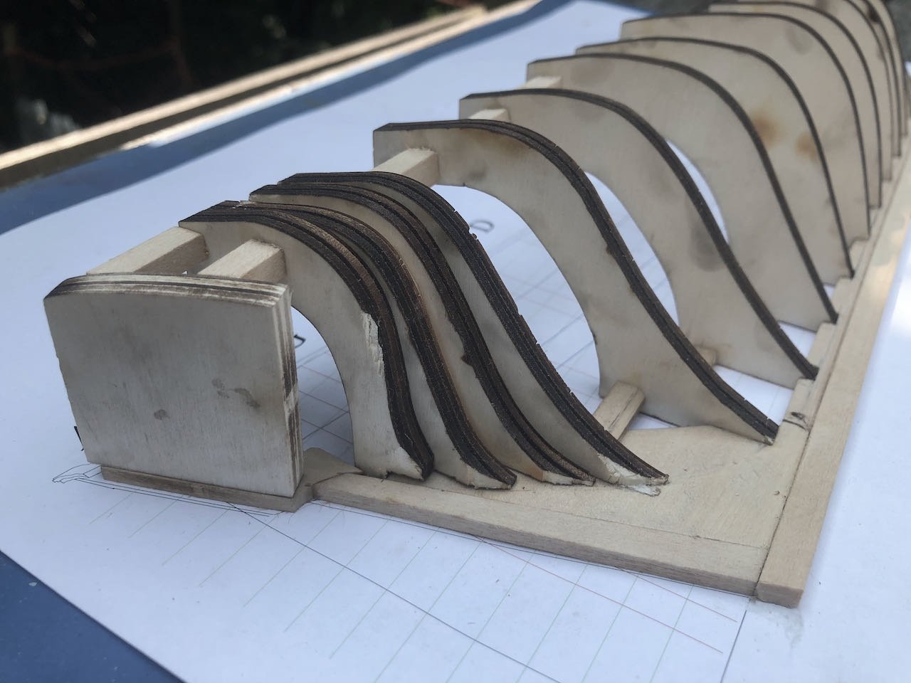
The framing is installed and braced. I didn't take in-progress photos as this is well-documented elsewhere and I didn't think I had anything to add. Stern: Bow: These frames are going to need a LOT of fairing. They seem really uneven, and I don't think it's my installation as they're all nice and square and the tops line up fairly well with the rail on the plan (when checked using a square). They're just really inconsistent. For example, look at the gap between these: These: Or these: I'm trying to decide whether to sand down the high frames or build up the low frames. I'm leaning toward sanding down as the frames are plenty thick, and this is overall easier than applying lots of filler strips, which would still then need to be sanded down. Neither the official build log nor the instructions make any mention of this sort of thing, just vaguely mention fairing. So I can't be sure whether it's a manufacturing/design flaw or somehow a mistake I made, but I did find mention of it in some other build logs I read, and it's a bit disappointing as some inconsistency is to be expected but this seems extreme. Oh well. Probably going to break out the Dremel for this, though I normally prefer not using power tools.
.jpeg.5e03bbd6cdb9c707f6a70b8993aa5939.jpeg)
-
NRG VIRTUAL WORKSHOP - AUGUST 21
Cathead replied to kurtvd19's topic in NAUTICAL RESEARCH GUILD - News & Information
I'm in. Sounds fun. -
I strongly suggest this resource as well: https://www.uwlax.edu/murphylibrary/collections/special-collections/steamboat-photographs/
- 86 replies
-
- 2
-
-
- king of the mississippi
- artesania latina
- (and 2 more)