HOLIDAY DONATION DRIVE - SUPPORT MSW - DO YOUR PART TO KEEP THIS GREAT FORUM GOING! (Only 13 donations so far - C'mon guys!)
×


Cathead
-
Posts
3,482 -
Joined
-
Last visited
Content Type
Profiles
Forums
Gallery
Events
Everything posted by Cathead
-
 If they aren't contacting the bulkheads, they're not bent properly. Based on your photos, shimming isn't going to help because the plank is bowing away from the bulkhead and the next one's going to be much worse. I'll head over to your build log from now on (link here for others interested).
 -
Interesting. Those aren't the most helpful instructions I've ever seen. They say nothing about tapering, though my instinct is that it would help (though without actually handling the model I don't really know). I think I'd start by pre-bending the planks and see if they sit right (as that can be undone, unlike tapering). Some people soak them and clamp them in place to let them dry, others apply dry heat with a planking iron or other source, then clamp them in place, or even both (soaking followed by heat application). Either way, again, the idea is to get the plank to hold the shape you want before glue is used. If it won't sit right on its own, it'll put too much tension on the glue joint, especially with so few frames providing support. If you're wondering how to do the clamping, there are really good photos and examples of different methods in the tutorials (my favorite is to use simply office-supply binder clips). The good news here is that all you're going for is a solid surface; the planking doesn't have to "look" good as it gets an overlay, so you have a lot of leeway. Unlike, say, if this was a wooden sailing vessel hull where accurate planking runs are a core part of the appearance. Try bending a few planks and let us know how it goes! Edit: Meant to say, if/when you start a build log for this, let us know here so we can follow you over. Otherwise it can be easy to miss a log being posted in all the activity on MSW.
-
Andrew, Thank you for sharing this shattering news. Although it's not the same, in November my wife and I lost her father, who died while we sat with him, and to whom we were both very close (he was another father to me). We, too, are buried under a mountain of paperwork and bureaucracy, while helping a mother in law with cognitive challenges. I had to pause while typing this as I broke down. I say all this simply to note that, in some small way, we recognize your grief and struggle and will be thinking of you and wishing you well. I wish I could offer more.
-
It looks like the planks aren't taking their intended curve properly, maybe helped along by the lack of frame fairing. Did you pre-bend them using water and/or heat? That's the standard approach, which rearranges the wood fibers to hold their shape when dry/cool. Most planks won't want to lie in their intended curves without doing something along those lines, it's the nature of hull geometry. Gregory is right that adding some thin material to the frames can fill that space, but that's not necessarily going to fix the problem overall, as each successive plank may keep bowing outward unless you get them bent properly in the first place. I.e., it looks like those planks are bowing outward, not sitting in the proper orientation with just a thin, even gap above the frame. Kits sometimes do get bulkheads wrong, requiring such spacers, but the first step should be assuming that the plank needs work, not the bulkhead. For example, you may also need to be tapering these planks, which helps them take the intended curve (as most hulls narrow toward the stern, each run of planking has to get thinner than it is at the full width amidships). I can't tell from your photo angle if you've done this or not. Rule of thumb, test-fit every plank using clamps before gluing. If it doesn't sit properly with the right bend, something needs to be addressed. Can you share with us a photo of the directions for this step and what the planks look like at the transom? Do the directions say anything about tapering planks? Is there a drawing of how the kit is meant to look at this stage? More information will help us give you better advice. Other broader suggestions: Read through a few planking tutorials here in MSW to ensure that you understand the general principles. Search for other build logs for this model and consult their photos and methods (for example, here's one not on MSW that has lots of detailed photos that I found in 30 seconds of searching). Start your own build log that tracks everything you do on this model. Starting new topics for every question you have on this specific build (looks like this is your third) clutters up the forums by repeating questions already asked and answered elsewhere, while making it harder for people to answer your questions (as they don't know what else you've done or asked on your model). We'd love to help you learn the skills of this really fun hobby, so keep at it and help us help you by providing more information and organizing your questions in a way that will be easier to answer as you progress.
-
Looks a bit like my bedroom as a kid! What a wonderful gift! Life certainly gets in all of our ways, thanks for the update.
-
Thanks for the update, good luck with the surgery.
-
Lars, how are you coming along? The model looks great so far.
-
How's your model coming? You got off to a nice start, I hope you can keep working and keep us updated.
-
How are you coming along?
-
You've gotten this far, any further progress?
-
Whatever happened? Have you started the new kit, or still fiddling with this one? Interested minds want to know!
-
Or this winter?
-
Any further progress? I'd hate to see such a promising start get mothballed. Hope you'll let us know what you've been up to.
-
Any luck finding a job or getting back to the model?
-
Haven't heard from you in a while, are you still working on this? We'd love to hear about your progress.
-
You were right about this, that bedroom must have been some project! Have you returned to this model? We'd love to know how you're progressing.
-
New Young Model Builder from Minnesota LOOKING FOR ADVICE
Cathead replied to Kenna's topic in New member Introductions
We haven't heard from you in a long time, how did your project come along? You had a lot of people interested, I hope you can update us! -
It's been a month, how is your model coming along?
- 602 replies
-
- 1
-

-
- Flying Fish
- Model Shipways
- (and 2 more)
-
How is your build coming along?
-
Glad to see another convert. I, too, got into wooden modeling after doing lots of other styles and find that nothing is as challenging and fulfilling to me in terms of craftsmanship and results. That looks like enough warp to need fixing. First step could be to wet it, then weigh it down thoroughly on a flat surface and let it dry. This is a fun prototype that I've always longed to build, as a geologist and naturalist. If it's of interest, a few years ago (seems like a lifetime) I was fortunate to visit a full-scale Beagle replica being built in southern Chile. I posted a number of photos here, which you're welcome to peruse if they'd be of interest or use as a reference or inspiration. No promises that it's 100% accurate, but it might be useful nonetheless. Looking forward to seeing this come together!
-
Good to hear you enjoy planking as some people seem to dread it. Not familiar with this model so I'm interested to see where you go with it.
-
A good start on an interesting kit, it'll be fun to see how it turns out. Glad to see you got the photos working.
-
Chaperon by joep4567 - 1:48 - Sternwheeler
Cathead replied to joep4567's topic in - Build logs for subjects built 1801 - 1850
I'm curious about your decision-making on having the hog chains arc so high above the hurricane deck. Is this a personal aesthetic decision or are you basing it on a different prototype? -
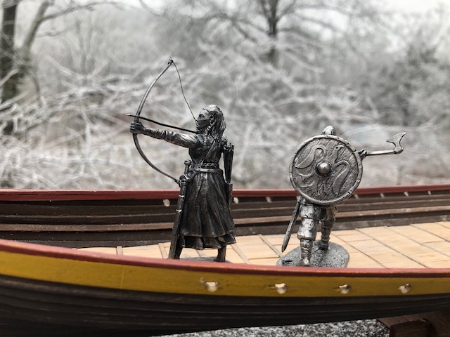
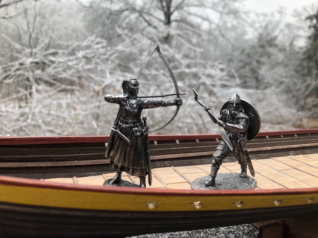
Oh, cool! Thanks for sharing that. I thought the style looked authentic when I chose that figure, but didn't realize there was a specific precursor. Also, here's a panorama shot of the ice storm landscape here. Notice the copse bending into a wye at right.

-
Happy New Year from the Viking shipyard. We're in the middle of a moderate ice storm that's hanging in the balance of getting much worse vs. being manageable. Seemed like an appropriate backdrop to share a few holiday photos with the latest additions to this build's arc, two more figures and a Danish mead. We brew a lot of mead ourselves, but Mrs. Cathead found this and thought it'd be a fun comparison to our products and highly topical. Speaking of mead, one of our favorite versions is pear, which I make in early summer after thinning the pears in our orchard. The roughly golf-ball-sized green pears get chopped into the initial ferment, infusing their fruity flavor into the mead and making a really distinct final product. It's a great way to use these otherwise wasted fruits. However, we need this ice storm to get no worse, as here's what the pear trees look like at the moment: The ice itself isn't a problem (in terms of temperature) but if it gets much thicker branches will start breaking, and that IS a problem. Getting back to the model, here are closeups of the latest crewmembers: I've wanted at least one proper axeman, and I really like the raven on his shield. And I thought Mrs. Cathead should have representation as well. Again, best wishes for a better 2021 for all of us.