
HOLIDAY DONATION DRIVE - SUPPORT MSW - DO YOUR PART TO KEEP THIS GREAT FORUM GOING! (Only 13 donations so far - C'mon guys!)
×


Cathead
-
Posts
3,482 -
Joined
-
Last visited
Content Type
Profiles
Forums
Gallery
Events
Everything posted by Cathead
-

Chaperon by joep4567 - 1:48 - Sternwheeler
Cathead replied to joep4567's topic in - Build logs for subjects built 1801 - 1850
I can imagine! You did a nice job. -
What you need to do is learn how such models are built in general, and then apply those skills to this (or any) model. Take the time to read the excellent planking tutorials here on MSW. Make a few mockups and practice the techniques described. When you understand the skill, apply it to your model. Do not expect a magic tool to replace knowledge, skill, and patience. The technique you are trying is akin to trying to learn to play trumpet by memorizing all the finger combinations to a specific tune, rather than studying music theory and learning how the trumpet actually works. Once you master those, you can play all sorts of songs. Otherwise you'll bang your head against the wall trying to learn one song without ever really understanding the instrument.
-
I'm going to be a bit of a young curmudgeon here and say that I did not find most of the standard books on wooden ship building particularly helpful when I was getting started 4-5 years ago. Most of them felt very out of date, frankly, and really weren't relevant to the quality and development level of modern kits. And this is coming from a voracious consumer of books who loves to learn by reading. As Roger says, a well-designed modern kit, with good instructions, will likely teach you at least as much as a decades-old book, and you'll be doing while you learn. As will spending time engaging with this forum and reading others' build logs. Even as references, books may not be as handy as the internet for a beginner; eventually you may want the definitive tome on 18th century rigging practices, but at any level of introduction to the hobby you may well be better off learning from others online and searching for the specific answers you want. Not to mention that videos are often better teachers these days than old books. Everyone learns differently, so this may not apply to you. But at the very least, you might consider requesting a few books through interlibrary loan to see if they are actually good matches for you before you splash out lots of money for a library. I quickly outgrew what little I did learn from the books I bought, and now wish I'd put that money to better use as the books now gather dust since they became irrelevant within a year, especially once I found MSW with its far broader scope of far more up to date information and advice.
-
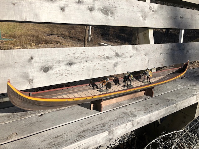
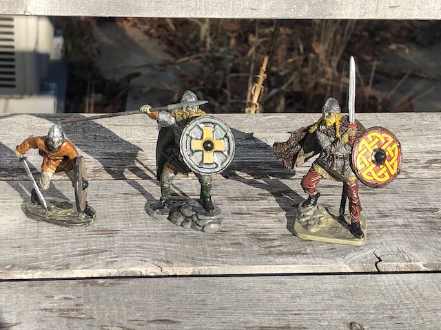
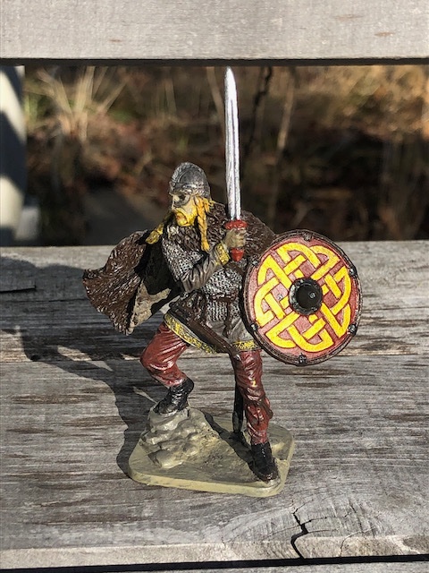
Wow, that thing is huge! Quite a bit bigger than Skuldelev 2. Petr is right, it's not a specific reproduction and in fact seems to combine styles and ideas multiple eras to create a sort of idealized craft. For comparison (figures from sites linked below): Dragon Harald Fairhair (ship in the video) 115' (35 m) long 26' (8 m) wide displaces 80 t sail area of 260 square m crew of at least 100 Skuldelev 2 98' (30 m) long 12' (3.8 m) wide displaces 26 t sail area of 112 square m crew of around 70 Thanks for sharing that video, it was a nice overview of various steps taken in construction. As for the current project, the deck is done! I rewarded myself by painting the third figure. Meet Sigtryggr, again named for a character from the Saxon Tales books but this time also a real historical figure. The real Sigtryggr was a Norseman who ruled in both Dublin and Northumbria, the former making him especially appropriate for this version of Skuldelev 2 (which was built near Dublin, though over 100 years after Sigtryggr's time). He's the most ornate and wealthiest of the three figures I've acquired, with his fur cloak, fancy shield, and cloak with embroidered linings. I tried to match his color scheme to the ship's. Here are all three figures: And here they are on the completed deck: This was a nice milestone to reach. Not sure what I'm going to work on next, but thanks for sticking with me.
-
Excellent! The rounded sides of the "look-in" really work well, and the second round of carriages is a definite improvement. Happy Holidays to you too!
-
Good to know this is still under progress, thanks for updating.
-
Nicely done! The time report is certainly interesting, I've never had the patience to do that.
-
The deck is mostly completed. I still haven't decided what to do about riveting. Leaning toward not bothering, as I'm just not sure I can do it right (or have the patience to do it right) and would rather it not be present than do in a poor, distracting way.
-
Ugh, what a frustration. Best wishes for getting it the way you want!
-
What a fantastic project! I'm quite interested in traditional Chinese cultures as I work with many Chinese authors in my capacity as a scientific editor. My last scratchbuild also attempted to reconstruct a vessel about which little was known above the hull, so I have some appreciation for the complex research and decisions involved (though yours will be far more difficult). I'm struck by how much those planking cross-sections look like a clinker-built Viking longship. Obviously the bulkheads don't match, but the profile is quite reminiscent.
-
Brian, The park may be closed to visitors but staff may still be working or at least available. The core NPS jobs are permanent hires, it's not like everyone's been let go, and they can't just shut the gates and ignore everything. So there's a decent chance someone is still monitoring contact info and could get back to you. They give basic contact info (phone # and an email form) at the link below, could try that and see if anyone responds. If you can make contact, the rest might work as the right staff member might be able to pass you along to the right historian or whoever. https://www.nps.gov/vick/contacts.htm
-
Great to hear from you again. Always nice when a modeler returns from hiatus. She certainly looks nice.
-
Have you tried contacting the museum with this question? Current staff may not know, but they may well be able to reach out to someone who does.
-
I just stumbled across this fascinating build and so will jump in late. Great start with such an interesting and unique vessel.
- 179 replies
-
- 2
-

-
- longship
- Helga Holm
- (and 1 more)
-
Maybe you'll do a better job than me! Certainly there are things I'd do differently if I were to repeat my kit.
- 48 replies
-
- 1
-
-
- dusek
- viking knarr
- (and 1 more)
-
Chaperon by joep4567 - 1:48 - Sternwheeler
Cathead replied to joep4567's topic in - Build logs for subjects built 1801 - 1850
Depending on how crazy you're feeling, there can be a variety of pulls hanging from the ceiling (connecting to the engine room, for example), speaking tubes, a spittoon, etc. One especially visible detail would be the long wooden lever used to "lock" the wheel in place if the pilot needs to step away (called the bridle, I believe). -
Chaperon by joep4567 - 1:48 - Sternwheeler
Cathead replied to joep4567's topic in - Build logs for subjects built 1801 - 1850
Creative way to get around having to drop the lower part of the wheel through the floor. All looks good. What other details are you planning? -
Seems to me that a topsail schooner could be a good choice. It's a step up in complexity from the Armed Virginia Sloop, so would be a new challenge. Lots of blockade runners and smugglers used such craft. You could adapt something like BlueJacket's Revenue Cutter to play for the opposing team, so to speak.
-
Good question. I don't know, but my guesses include (a) not directly exposed to seawater, (b) easily replaceable so why waste the tar, and (c) the deck isn't meant to be sealed like the outer hull. I also wonder what the texture of tarred wood was like, and whether it would be more difficult to walk on.
-
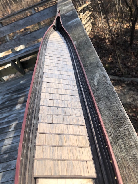
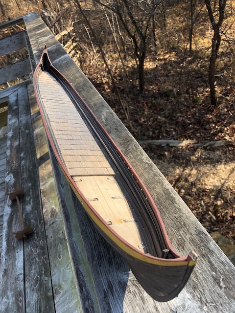
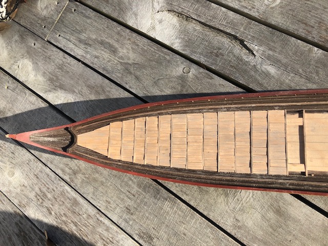
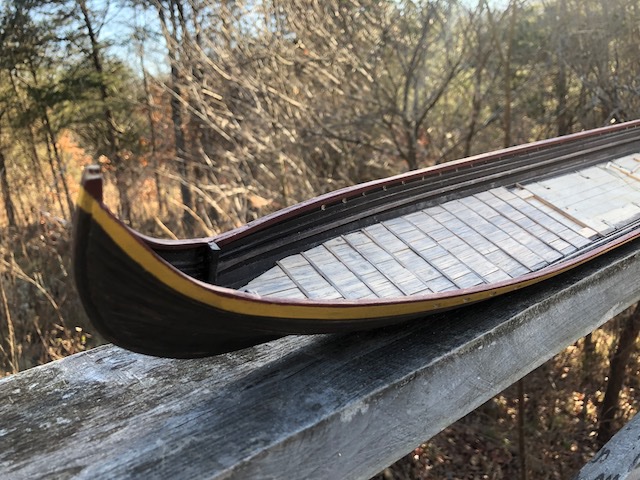
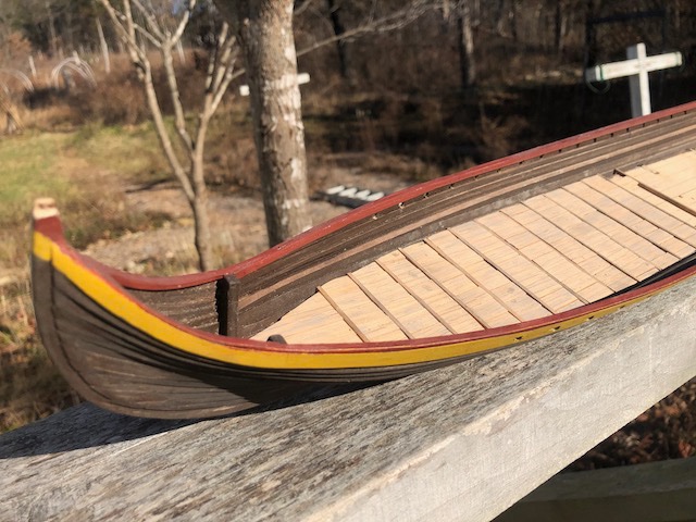
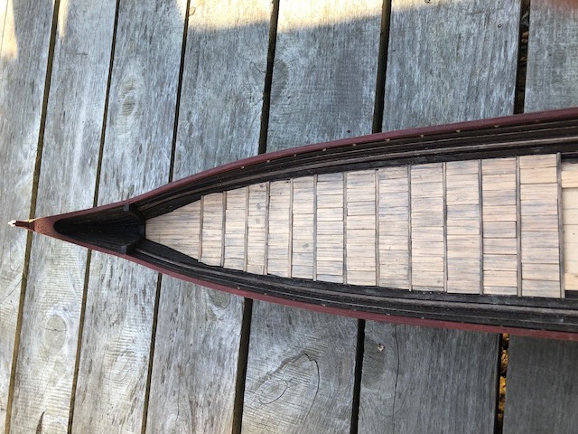
More decking progress. I took paired photos in sun and shade as each highlights different aspects of the texture and color. Really pleased with how this is coming out: This is a great task to just keep plugging away at in free moments. It's a lot of manual work but pretty straightforward now that I have my system perfected. Probably another week or two and it'll be done.
-
Welcome! I'm currently building the 1:35 Dusek longship (see link in signature), another case where no log exists for the large-scale version, only the 1:72 version. I've found the kit to be rather problematic and you may well benefit from reading through my frustrations, mistakes, and solutions, even if you proceed differently, as I wouldn't be surprised to find many issues mirrored between the two kits. I hope you'll stick with it; mine is finally starting to look like something and I think will turn out well. Good luck and I look forward to seeing what you do with this interesting vessel.
- 48 replies
-
- 1
-
-
- dusek
- viking knarr
- (and 1 more)
-
I feel that he's generally good about the broad context but has gotten ever-sloppier with the details as the series goes on. For Pillars, my understanding is that he plunged into the details of period cathedral building and it comes through in the narrative. In the later books, he takes less time to understand what he's talking about and just writes the same story with the same characters with a few details changed to hint at a different era. But never once do you get the sense that he dove as deeply in the context of the others as he did for Pillars. Pillars is also the only one where there's really a deeper literary narrative behind the character arcs (the mystery of Jack Shareburg) that ties all the character arcs together in a creative and powerful way by the end. I noticed the same things Roger did (laughable maritime scenes, "Lenny", various other strange and awkward stuff). Absolutely "winging it" in an effort to churn out the next best-selling potboiler rather than writing an actual work of literature (which Pillars aspires to and generally achieves). He does the same, even worse, in E&M. If you all want a really interesting, highly detailed, fascinating, and compelling historical novel set deeply within English history, try An Instance of the Fingerpost. It tells the story of a mystery in 1600s Oxford, sequentially from four points of view, tying in a vast set of knowledge drawn from the religious, scientific, and political tumult of the period. Just about the best-crafted historical novel I've ever read and one that really needs to be read multiple times to fully appreciate how many threads he's weaving together.
-
Pillars is by far the best, an excellent book that stands up to repeated rereads (at least four for me). I'll never read the others again. As with many authors, he got it right once, then started cashing in on the formula with predictable results in terms of quality. I mean, I've read them all, he obviously writes stories that draw readers in. But each successive book felt less compelling. E&M, for example, might work ok if you hadn't read any of the others, but by that point he's following some pretty deep narrative ruts and all the characters are recognizable as reflections of the same cutouts in previous books. And, most damning to me, E&M never once feels like it takes place in its intended era. It's just recycled Pillars with a few vague references to Vikings thrown in, along with a laughably silly "battle". Any literary criticism is opinion-based, and we're all entitled to feel differently. Others' mileage may vary.
