


Cathead
-
Posts
3,538 -
Joined
-
Last visited
Content Type
Profiles
Forums
Gallery
Events
Everything posted by Cathead
-
 Fascinating and good-looking. Would there have been any reason to ensure that the upper- or lower-most line of plating was In or Out?
 -
If you feel like studying up on rigging and sail management, you can learn how that was really done. Your method certainly achieves the desired visual effect. I agree that it opens up some nice sightlines.
-
Micromark appears to host a version of the instructions. Pictorial version here: https://www.micromark.com/Instructions/85648 Mississippi.pdf Written version here: https://www.micromark.com/Instructions/85648 Mississippi Detailed Instructions.pdf Found these with a 30 second Google search. Further digging might turn up other options.
-
Just found this build of a kit I'm very interested in after reading about its release. Great work so far and a useful early tutorial for later adopters. I second the Caroline Alexander recommendation, by the way.
-
Brian, that makes a ton of sense. I can easily see how trying to shape actual brass rails in a consistent and parallel shape could be maddening, and how much easier styrene would be. Again, you'll be in my thoughts as we go through a similar period.
-
Lynn, good start so far, and you're right away (re?)discovering the world of confusing instructions. As an editor, I've contacted multiple model companies offering to work with them to improve the clarity of their instructions, but none have felt it was needed. Shrug. Looking at the final model, I don't think this issue will matter. Whether or not the knee comes all the way up to the top of the lower stern transom doesn't appear to have any structural significance, and that area ends up covered anyway. So I suspect you're fine. Would be far from the first time that instructions developed from a prototype don't match the final commercial product. In fact, I wonder if they changed the part size. Look at the drawing on page 3, which appears to show the stern transom knee being the same size as the bow transom knee (not quite a bit larger as in the kit parts), and neither reach the top of their respective transom. So I wonder if, in final kit development, they made the stern transom knee better (better stability for the model?) but didn't revise the instructions to match?
- 160 replies
-
- 4
-

-
- Model Shipways
- norwegian sailing pram
- (and 1 more)
-
Lovely work as always. Correct me if I'm wrong, but are those railroad irons just essentially iron rails, and that's why you were looking to source HO-scale track? I wish I'd known, I have a lot of leftover brass track that I would happily have sent you for free. Apologies if I missed that detail early enough to have made a difference. It's been a distracting time here and I maybe haven't been reading as closely as I should? Your approach certainly does and will look great. Condolences on your loss, I've been there recently too and am still working with the aftermath.
-
Very attractive, a result to be proud of.
- 50 replies
-
- 2
-
-
- model shipways
- 18th century longboat
- (and 1 more)
-
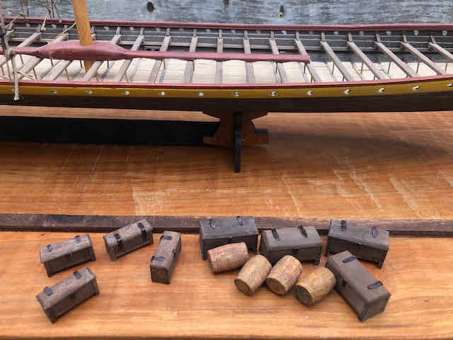
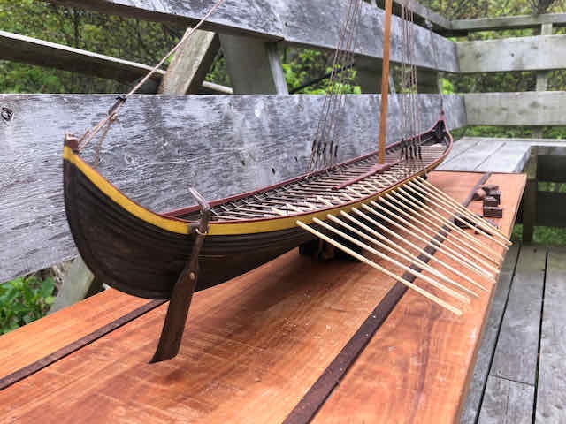
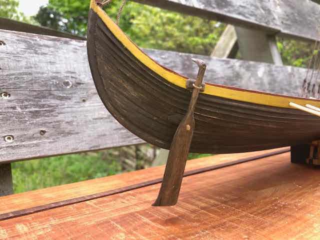
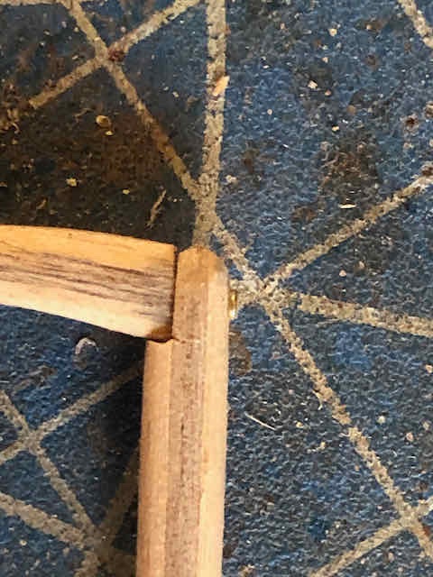
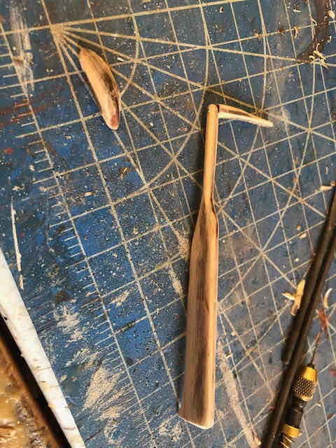
Making the rudder was fairly straightforward. It comes in two pieces that need to be carved and sanded from their solid block shape into the rounded form necessary. Here's a look at this in progress: I attached the handle by carving out a socket for it, then drilling a fine hole that let me set a brass nail into the joint: And here's the finished product mounted on the hull after staining: I'm slowly plugging away at oars; I can only handle making ~6 at a time before I get too cramped. Here are the oars so far, loosely mounted for display: I also built four more chests, using a slightly different design but similar method. These are smaller, to add some visual diversity. So here's the cargo so far: And a slightly broader view with the ship in the background: Feels like progress. Really, the oars are the holdup now. But I keep thinking of other details to play with, like a good anchor, and bundles of weapons, and finishing the shields, and so on. This will probably drag on for a while. But it feels close!
- 323 replies
-
- 10
-
-
I agree, Syren rope is heads and tails above regular kit rope. Things continue to look great here!
-
Thanks for posting that, Kurt. I was pretty shocked; I had settled in on the couch to watch the program with no expectation whatsoever of needing to have my camera or mic on, and had to scramble when that came up! I couldn't have gotten anywhere on this project without the support and mentorship of so many people here.
- 599 replies
-
- 7
-
-
- sidewheeler
- arabia
- (and 4 more)
-
NRG Capstan Project
Cathead replied to tlevine's topic in - Build logs for subjects built 1751 - 1800
Just purchased my version. Won't be getting to it right away (need to finish my current project first), but this gives me incentive to keep moving. I have a bunch of wood that I cut and milled on my rural property (cherry, maple, walnut), and have been curing, as I want to start building with my own materials, and this will be a great early step in that direction. I do have a question, though. In both the PDF and here, you mention the need for a "hobby sized circular saw". In the woodshop parlance I'm familiar with (having grown up with a cabinet-maker stepfather and having a variety of building experience myself), a circular saw is a handheld saw like this: Or sometimes a miter saw like this: However, I'm pretty sure from context you're referring to a table saw, like the popular Byrnes model: That's what's shown on p. 10 of the PDF. Can you clarify what you mean, and perhaps consider changing the wording to say "table saw"? I actually went Googling for a "hobby size circular saw" to see what you were talking about and couldn't find anything, so I doubt I'd be the only person potentially confused by that wording. Thanks for putting together this great project! -
CA is nasty stuff. The bottles specifically warn against skin contact or fume breathing. I'm pretty sensitive to most chemical fumes (even things like bug spray and perfume set me off), so use CA as little as possible and only for short periods. Otherwise it gives me a headache very quickly. I find paint to be the same way; I've kept my focus on acrylic paints with little odor because some of the other ones destroy my health and comfort in short order. One of the things I really love about wooden modeling (as opposed to the plastic modeling I did much of my life) is how relatively benign wood glue is compared to most plastic cements and other adhesives. Your figures look great and do add a lot of life. I started painting figures for the first time during my current project and found that I really enjoy both the project itself, and the results.
-
On MSW, this is called the signature, and here's a thread that explains how to do it. My wife is a scientist who has also worked in male-dominated fields and has often been cautious about revealing her gender in related online or publication settings because she has definitely experienced discrimination and other issues. When I joined MSW, I was fairly cagey about identity at first because I didn't know what I was getting into. I've opened up quite a bit since then as I've learned just how friendly and helpful this community is. I'm so glad you feel comfortable as well. There's certainly an innate assumption that most modelers are older men (rather justified by the actual demographics), just as I tend to get odd looks as a younger man going into craft stores! And there can be a bit of a "boy's club" mentality here at times, just look at the nature of the prevalent jokes about "admirals", "honey do lists", and so on. But I think all communities benefit from diverse perspectives and participants, so you're all the more welcome for that reason. Thanks again for sharing your work with us and I hope you'll enjoy a long and worthwhile time here on MSW.
- 85 replies
-
- 4
-
-

-
- Lowell Grand Banks Dory
- First Build
- (and 2 more)
-
Congratulations, she's beautiful. A result to be proud of, and even more to the point, you did a great job learning and applying what you learned as you progressed. I look forward to seeing what you do with the pram! If you remember, once you start that build log, let us know here as I'd like to follow it as well. By the way, I'll be in Kansas City next week, among other things at the Tuesday and Wednesday Royals games.
- 85 replies
-
- 3
-
-
-
- Lowell Grand Banks Dory
- First Build
- (and 2 more)
-
My favorite way to handle this issue is with a needle threader. These are sold in various crafts shops and also by model suppliers like Model Expo. They're extremely useful and versatile. Just make sure to get a packet of a few, because they can also break given their delicate nature. Another tip is to use a bit of glue to seal in one end of the rope/line in question, as even tiny frayed ends can catch on a hole and make it really hard to pull the rope through. You can even use a knife to shave the glued end into a pointed shape (like its own needle) that will help it pass through. You can then just cut off the 1/4" or less of glued area once the threading is complete.
- 85 replies
-
- 4
-
-
- Lowell Grand Banks Dory
- First Build
- (and 2 more)
-
Pedantic alert, those aren't really lifeboats, but rather work boats. Their primary purpose wasn't lifesaving or safety, but rather as auxiliary craft for all sorts of everyday needs. For example, a research paper on Beagle's boats (delightfully titled "The Beagle's Pups") notes that she "carried seven open boats of varying types, which were employed in surveys of waters which the ship could not reach." Other uses would have included carrying water casks to and from shore (along with other provisions), towing the ship during calms, allowing harbor access when quays weren't available, and so on. Just mentioning this as you've expressed an interest in learning as you go. You're continuing to make great progress!
-
Steamboats and other rivercraft - general discussion
Cathead replied to Cathead's topic in Nautical/Naval History
When this project first came up, I searched that UW collection for the Biddle, hoping to be helpful, and came up with nothing. I recently bought a copy of the NRJ article on that keelboat (more accurately, barge) as I'm considering that as a future project.- 281 replies
-
- 2
-
-
- Steamboats
- riverboats
- (and 3 more)
-
Steamboats and other rivercraft - general discussion
Cathead replied to Cathead's topic in Nautical/Naval History
That's a cool looking park for sure, though I have to say that replica keelboat isn't all that accurate. Though it doesn't really matter as it was probably a lot easier to build that way and 99% of visitors won't care while getting a reasonable taste of the size and layout of the original vessel. Pedantic sticklers like me aren't really the target audience!- 281 replies
-
- 2
-
-
- Steamboats
- riverboats
- (and 3 more)
-
Same here. My problem is I'm always ready for the next adventure when I'm about 80% done with the current one. Look out for "I-don't-want-to-deal-with-this-itis" when that stage comes!
-
If you end up doing more projects like this, you might consider an inexpensive planking iron. These apply heat to planks, helping them bend easily and quickly. It speeds up the process quite a bit and can eliminate or lower the need for awkward clamping and waiting for drying. That being said, tiny boats are tricky no matter what and easily can be maddening.
-
NRG Capstan Project
Cathead replied to tlevine's topic in - Build logs for subjects built 1751 - 1800
Toni, where does one view/buy/download the monograph and plans? You gave no link and the NRG's Plans and Projects page doesn't have anything listed for this. Forgive me if I'm being dense and missing something obvious. This is the first I've heard of this project and would like to know more. -
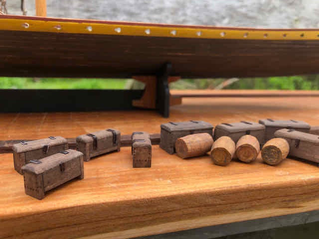
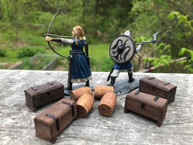
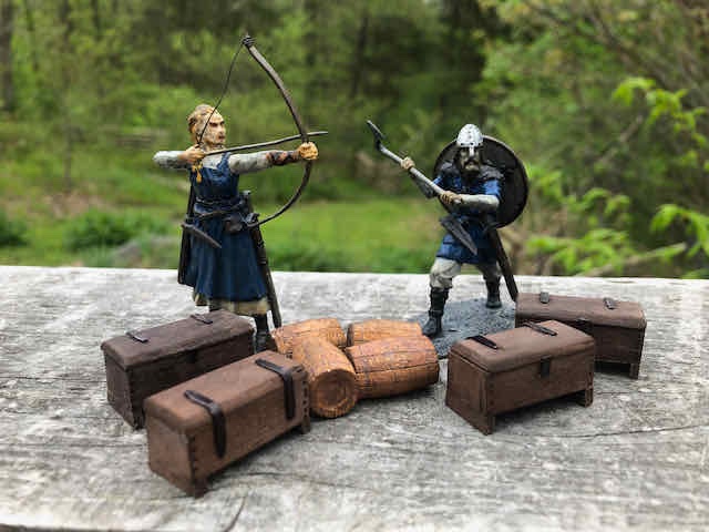
I took a shot at some cargo based on the above ideas. I didn't take any photos during the process so you'll just have to imagine. I'm also featuring the final two figures here, which I actually painted months ago but can't remember if I ever posted. These are a "his & hers" pair representing Mrs. Cathead and myself. The blue color isn't as likely but is our favorite color. And as a birdwatcher I very much appreciate this guy's raven shield. He also has a proper axe, unlike the swordsman and spearman I already painted. I thought these would give some good scale for the cargo. The crates are based on Steven's links. I assembled them from strip wood, painted them, then weathered them with pastels. The hinges are thin strips of styrene colored with a black marker. The barrels are dowels I sanded into a more barrel-like shape using a sanding disc on a Dremel. I then filed rough plank boundaries and darkened them with pencil. I also added some faint hoops with pencil. These were also pained and then weathered with pastel. Oh, I also used a carving tool on the Dremel to eat away a little bit of each barrel end to hint at the inset nature of a real barrel head and remove the shiny smooth dowel-end effect. None of these necessarily would stand on their own, but in a cluster they look pretty good and when they're in the hull among the thwarts I think will be quite acceptable. The real question is how many more I make. It took me most of the afternoon do to this. Mrs. Cathead looked at my project and said "You're procrastinating on making oars, aren't you?". Yes. Yes, I was.
-
Steamboats and other rivercraft - general discussion
Cathead replied to Cathead's topic in Nautical/Naval History
Very cool! Hard to imagine, now that the river's been destroyed by damming.- 281 replies
-
- 2
-
-
- Steamboats
- riverboats
- (and 3 more)
