


Cathead
-
Posts
3,550 -
Joined
-
Last visited
Content Type
Profiles
Forums
Gallery
Events
Everything posted by Cathead
-
 Do what you like, but for the record I'm not planning to leave any cats in my model cases...
 -
I'm out of words to describe this, but am so grateful I got to follow along. The fly seems poetic given your username.
-
Looking for plans or possible models of Magellan's ships.
Cathead replied to J11's topic in Nautical/Naval History
Louie, good to know. Understanding what isn't right can be as helpful as understanding what is! -
That distinct sail really adds life to the model. Well done!
- 28 replies
-
- 1
-

-
- Amati
- chinese junk
- (and 1 more)
-
Looking for plans or possible models of Magellan's ships.
Cathead replied to J11's topic in Nautical/Naval History
For what it's worth, there's a full-scale replica of the Nao Victoria at a maritime museum in Chilean Patagonia. I visited it a few years ago and took a series of photos, which you can review here. I don't make any claims about the specific accuracy of this reconstruction, but it does provide a different visual perspective than old drawings or paintings, so maybe it'd be useful as part of your portfolio of information? Example photo: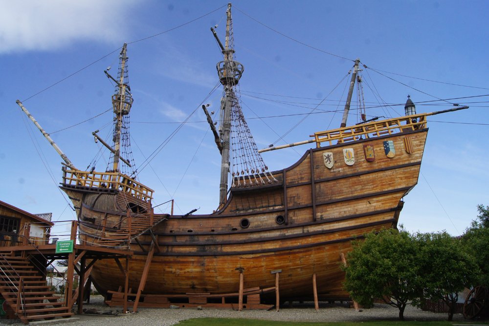
-
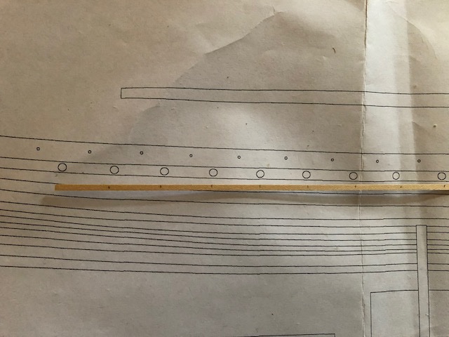
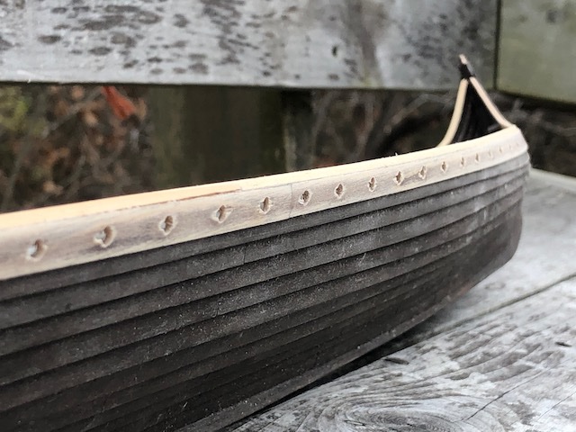
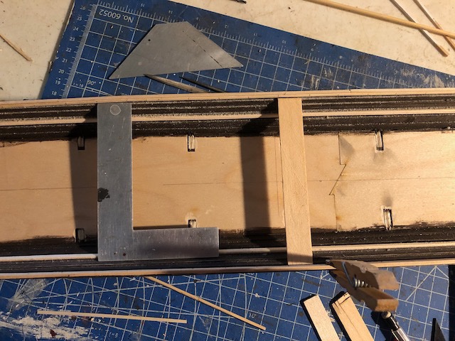
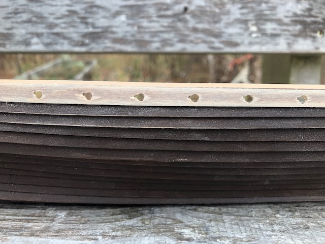
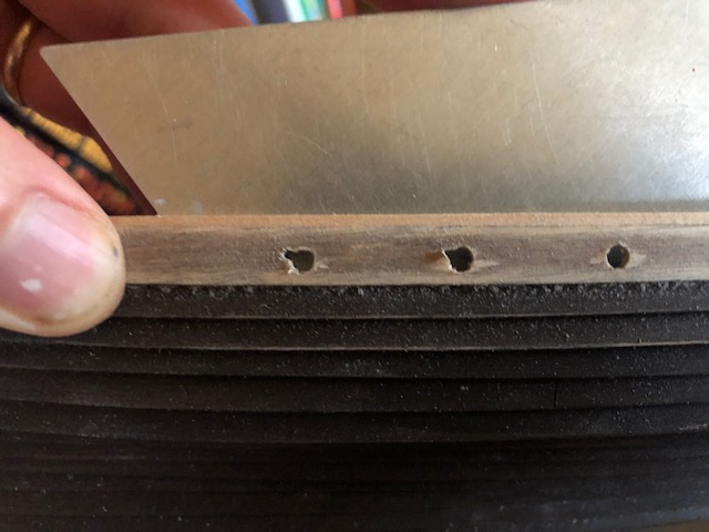
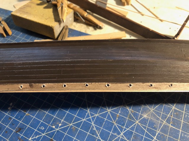
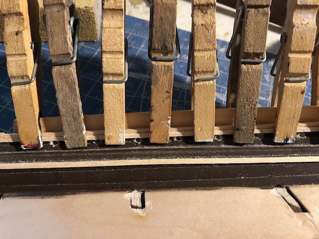
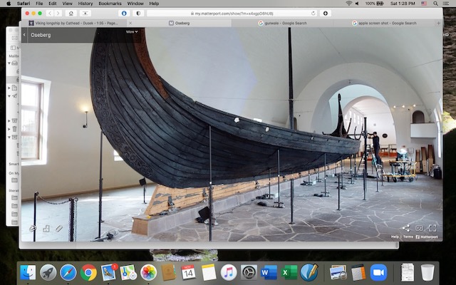
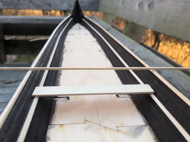
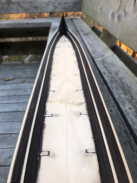
I've actually had a really productive morning and have Binho to thank for it. He posted a link in another log to this amazing high-resolution interactive walkaround of the Oseborg ship, which let me look at some interesting and important details that really helped get my head around a way forward. I noticed two really useful details: First, that ship has an abrupt change in planking angle between the lower strakes and the upper two; the latter turn sharply vertical and also don't blend into the stem but just into the lower planking. I wish I'd realized this a few weeks earlier, I might have been even more aggressive in "fixing" my wacky angled planking by just attaching a few more upright strakes rather than worrying about achieving a smooth curve all the way up. I'm not trying to reproduce Skuldelev 2, just making a representative Viking craft, so this would have worked. At the very least, it further justifies my smaller additions to the top of the model's planking. Here's what this looks like: Second, the oar ports on that ship are really close to the gunwale, not further down in a lower strake as they are on Skuldelev 2. They're also not drilled in evenly, there's quite a bit of random variation in their height from the gunwale, which you can sort of see above (follow the link to see it better). This suggested to me that I could get away with drilling oar ports in my altered planking after all, saving the need to make 60 tiny thole pins. In other words, since my planking ends at least a full strake's width lower than on the prototype, drilling oar ports in the right location by strake would make them way too low, which was one reason I considered doing thole pins on the gunwale instead. But the Oseborg way lets me put the oars back at roughly the correct height above the deck. So I mulled over the geometry for a while and decided to go for it. First, I used a thin strip of wood to transfer the oar port spacing from the plans to the model: I then used a square to transfer a few reference marks to the other side of the hull, then lined up the strip and transferred the rest of the marks: I wanted to drill from the inside out, as I needed to follow a narrow gap between the top of the next plank below and the reinforcing strips I added previously. But I also wanted to minimize tear-out from the drill going through the outer plank. So I clamped a moderately thick strip of wood to the outer hull, leaving gaps for the drilling locations: I started with smaller pilot holes, using my fingers to hold the plank really firmly to avoid weakening the thin glue joint with the next plank down: Here's what the first rough drilling looked like from the outside: Not too bad. I then used the full-sized drill bit to ream these out to the desired diameter, then did a bunch of sanding and filing to clean up the holes and the tearout. Next I decided to add the angled slots some of these ships had, cut into the sides of the oar ports, to better allow oar blades to slide through. Skuldelev 2 didn't have these, but Oseborg did, and I think they add some nice character. On the latter, they angled upward and toward the stern. My smallest rectangular file wouldn't quite fit into the oar ports, so I used a tiny triangular file to make a notch in the port, which allowed the rectangular file to get in while also making a clear indentation for me to follow. You can see this process below; from right to left, round port, initial triangular notch, finished rectangular notch. So I did all of this 30 times on the starboard side and am pretty pleased with the outcome: There's some final cleanup to do, which may wait until after painting as that always requires a bit more fine sanding once the grain is raised again. But I like the look and this gets me past a major hump. Next I'll finish the gunwale (need to run strips along both sides) and do the oar ports on the port side. Writing this, I just realized I should have done the port side first as a test, since in theory the starboard side is a better display side (the steering oar is on that side). Oh well. At least now I have a clear path forward for a little while, which feels really good.
-
What a fantastic resource! I've already discovered several details very useful to me in my own build.
-
That decanter is fantastic!
-
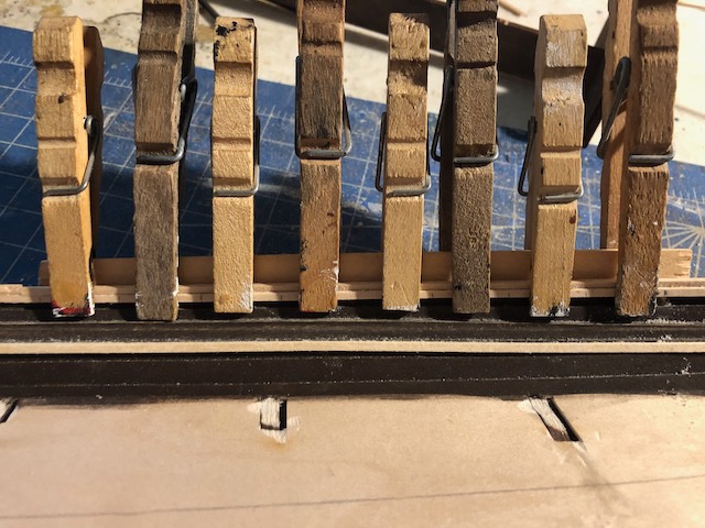
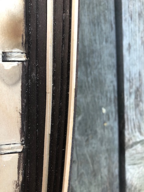
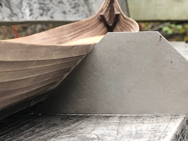
I set aside the riveting question for now as too complicated (I appreciate all the input) and worked on something else that was easier to get my head around. I initially meant to start on the deck, but realized I needed to do some other interior hull detailing first so I could paint it and be sure not to drip on the finished deck. There are various reinforcing strips run along the inside of the hull at various levels. This collection of stock photos has some pretty good interior shots of the reconstruction. The kit says to make these strips out of square stock, but none was supplied. I decided it would be hard to bend square stock to match the curve of the hull, so used two layers of flat stock left over from the deck planking of my last model. These bent really easily and could be layered up to the desired thickness. In the second photo below, you can see the lap joint between the two layers to show how this worked. One level serves to support the rowing benches, the other level is meant to stiffen the top of the planking. Thinking about this gave me a very good idea for "solving" the 45-degree planking tilt problem. I built up two layers of strips along the upper edge of the final strake, then sanded it smooth and horizontal. The next step will be to build up one more solid layer on top of this that will be level on top and vertical along the side; with a bit of sanding I don't think the transition will be too noticeable. This might not make sense until I finish, but here's what the sanded top looks like: The left side has been sanded smooth, the right has not. Can you see how the plank lies smooth and flat on the left, but rests on the angled edge on the right? The lower plank simulates a rowing bench (not to scale, just checking level and position). If you look closely at the image below of the modern reconstruction, you can see how the uppermost strake is actually a thicker square feature made of multiple pieces of wood (one down the middle, two more on either side). I'm going to try to mimic that to both raise the edge of the hull and bring it vertical and square. This will be clearer when I actually start doing it but I think I can get it right enough to improve the existing version. Look at the link above for more interior images that show this even more clearly. You might also notice that I painted the hull a darker color (undiluted walnut stain) to simulate a more accurate appearance. I'm going to use pastels to further darken this once the model is near completion. I'm also going to paint one or more upper strakes a different color. Next up, I'll work on raising those hull extensions and hope it turns out ok. Thanks for reading.
- 323 replies
-
- 11
-
-
Lars, Your model looks wonderful so far, especially for a second build. I'm sad that I just now discovered your thread. If it's of interest, a few years ago (seems like a lifetime) I was fortunate to visit a full-scale Beagle replica being built in southern Chile. I posted a number of photos here, which you're welcome to peruse if they'd be of interest or use as a reference or inspiration.
-
Chaperon by joep4567 - 1:48 - Sternwheeler
Cathead replied to joep4567's topic in - Build logs for subjects built 1801 - 1850
Nice fix! -
That's interesting, thanks! Pin heads do provide a better appearance. Still not sure I'm up for drilling those holes, but I suppose I could clip the heads off thousands of pins? I'll think about it.
-
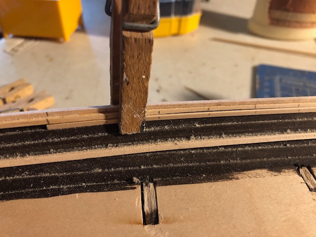
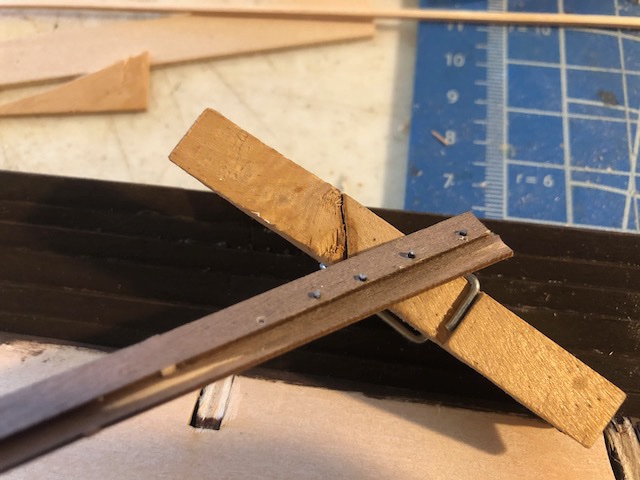
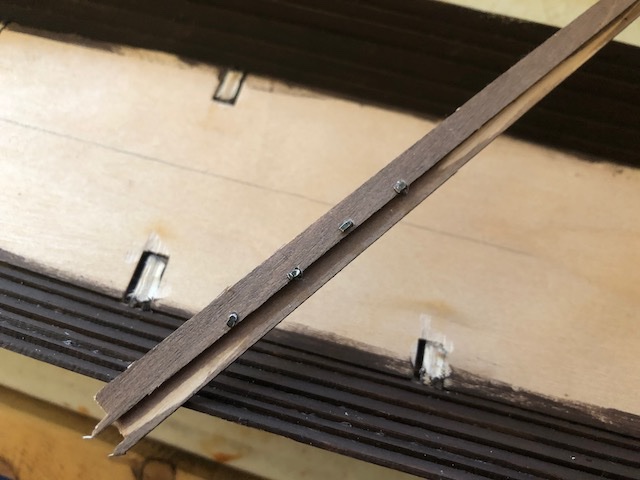
I have had a possibly crazy idea and I'm curious for input. I keep thinking about ways to add realism in other ways, to offset the problems. If the model looks neat enough, then it'll capture the essence if not the accuracy of the vessel. So my latest idea relates to the rivets that would have held the clinker planking together. On smaller models these could be simulated using a marker, but this is too big for that to work. So I made a testing jig of two plank scraps glued together and tried two different ways of drilling holes and inserting "rivets": Version 1 is thin black wire, inserted and cut off with nippers. I didn't try to make these perfectly aligned, this is a test run: Version 2 uses HO-scale model railroad spikes, which have a wider head, squarer head: I like the spike because their protruding ends stay black, while the wire is shiny and would need to be painted or blackened. But the wire is probably more realistic in shape. Plus spikes are limited in number and wire is infinite. My biggest concern is practicality. Even at a broad 1/2" spacing (wider than scale on the real thing) I'd need to do this over 700 times for each side, and I'd have to do it consistently enough to look good, through all the curves in the hull. I'd also have to do it without breaking the glue bonds between the planks, which are already weak. Ironically, this might actually help hold them together when finished if I used a drop of glue with each rivet, but getting there could be damaging. Plus, I'd have to align the hole through the planks to the other side, which would be especially difficult. It would look especially goofy to have a ragged line of holes/rivet ends on the inside that didn't follow the planking line, but I can't see how I'd keep it consistent through all the curves of the hull. My leaning is that I don't have the skills to get this right, and it could turn out disastrously since once I start I can't stop and go back. It would also take an extraordinary amount of time for a model that isn't that great overall. But the hull would look so much better with some kind of rivet pattern rather than just being smooth at this scale. Thoughts?
-
Chaperon by joep4567 - 1:48 - Sternwheeler
Cathead replied to joep4567's topic in - Build logs for subjects built 1801 - 1850
Very nice! Is there a slight mismatch in wall height where the flat part transitions to the angled part (just forward of the engines) and will that cause problems for laying down the hurricane deck? -
Both of these comments match my experience. Testing on scrap is never a bad idea, and I've had good success using needle files (twisted, not pushed) to gently widen holes. Good luck!
-
Would an option be to have the templates printed on single larger sheets of paper through an office store? I believe you can submit files online and pick up the printed product. That would mean the whole thing would be at one scale. Whether it would be precisely accurate to what you intended, I don't know.
-
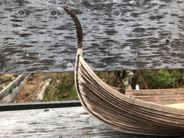
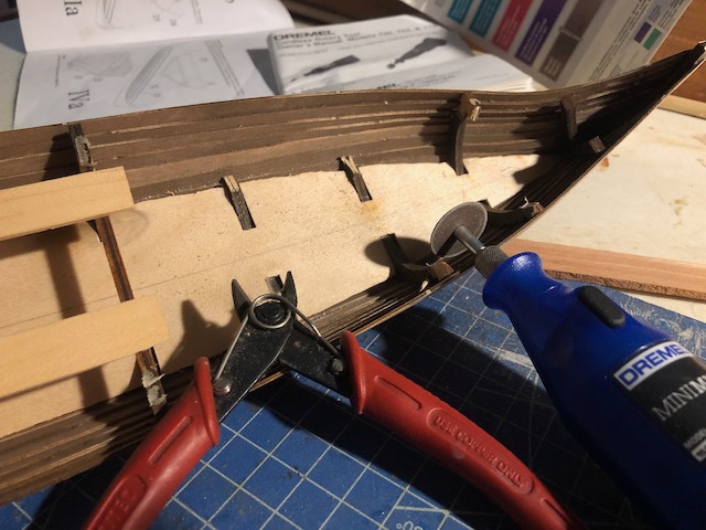
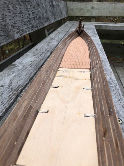
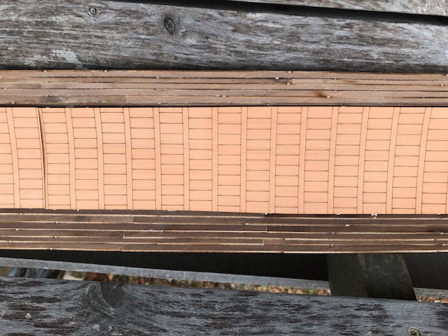
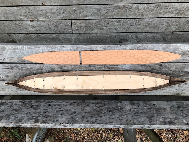
A bit more progress. First, I played around with various ways to make a tail at the stern. Lots of sources have coiled tails, but I was unable to replicate this with my tools and skill set. So after much frustration, I decided to come up with my own tail. I wanted it to be visually distinct, at least somewhat representative if not necessarily accurate, and able to be made from the same plywood as the keel so I could slot it in easily like the dragon's head. I finally hit on using the notched edge that mirrored one of the clinkered frames; I think it came out looking reasonably nice. Evocative, if not accurate. I then moved on to the major step of removing the frames. As you may or may not recall, these need to be removed above deck level as the real vessel had no equivalent structures. I did not glue the planks to the frames above that level in order to ease this process. It was still rather hairy, as there was no good access for any kind of saw or tool. I tried a small Dremel motor tool with a cutoff blade, but was terrified of slicing the planking. I tried a small razor saw and a knife, but the plywood is hard and they really didn't have a good angle either and doing it that way kept putting stress on the hull (I've had enough problems already with planks separating from one another). Finally I tried a pair of shears, which came closest to a flush cut and didn't risk damaging the planking. Here's what the first rough cuts looked like in progress (rejected Dremel also shown): For anyone making this in future, note that I cut away the top of the frames first, then the "ribs", as the top parts got in the way. Once all the frames were cut away, I used a sanding drum on the Dremel to finish lowering them to at or below deck level. This worked very nicely and was easier to control in terms of not damaging the planking. Here's what the cut-off and sanded frames look like: The kit provides a thin pre-scribed false deck, shown in part above. I think it's ugly and it doesn't quite fit my hull anyway. Here are a few more shots of it: From the beginning, my plan has been to discard this and install individual deck planking, as I think this will look a lot nicer. So that's the next major step to undertake. Finally, I want to return to my intense frustration with the shape of the hull. As noted before, this was supposed to finish at a near vertical angle, but instead the planking bowed outward and finishes at a roughly 45 degree angle that is well below its intended head amidships, as shown below. Also, if you look in the background of the photo below, you can see that the kit's final frame (which is supposed to remain in place) doesn't come close to matching the natural curve of the planking. I finally stopped trying to force the last few planks to meet this frame, which made the final planking go easier but results in a rather awful looking gap between frame and planks. In theory I could have avoided this by gluing the planking onto all the frames, but I didn't want to do that as it would have meant very delicate removal of the frames later on, including glue stains that would have been very difficult to get rid of. I thought that soaking and clamping the planks to the frame during gluing would have been enough, but clearly this hull has a mind of its own. If I did this again I might try it to see what happened, but the instructions were so poor that I had to make a judgement call on what to do and am now living with that choice. I really don't know what to do about this. I could try to add one or more new strakes, but (a) I don't have any good material for that and (b) they would have to go through a rather abrupt change in angle from the previous plank to get even close to vertical. I could leave it as-is, but it'll look ridiculous with oar ports drilled in facing the sea at a 45 degree angle and the really low freeboard will be awkward as well (the rowing benches will be near the top of the planking amidships). I've been thinking about installing oarlocks atop the final plank (rather than oar ports drilled in it) to at least raise the height of the oars, like those seen here and here. This is also because I don't like the idea of drilling 60 holes in this delicate model and having no way to fix something that goes wrong. My current plan is to work on the deck and let the hull decisions fester for a while. I often come up with new ideas or solutions over time, and the deck work is independent of the rest. Updates will continue to be intermittent. Real life is pretty hard right now, our time is being swamped by a complex and ever-worsening situation with my in-laws that I'm not going to get into online, but which is overwhelming our mental, emotional, and physical capacity to deal with other issues. Although hobbies can be healthy distractions, this project is anything but relaxing and I'm not finding a lot of time or motivation to work on it lately. Thanks for understanding.
-
Congratulations on moving forward successfully in every sense!
-
I've got a Viking ship you're welcome to finish. I'll happily pay to ship it to Australia. Otherwise it may end up at the bottom of my pond.
-
I think you mean "hoops", the metal rings that hold the barrel staves together. "Coops" contained chickens. The barrels look nice, as does the rest of the model so far.
-
Oooh, my turn to show off pedantic knowledge! Geologically speaking, porphyry is an igneous rock (formed from cooling lava), whereas marble is metamorphic (physically and chemically transformed from limestone). However, in the building trade, "marble" is routinely used to refer to any crystalline rock that can be cut and polished regardless of origin. "Granite" is the same way in kitchens and baths; most "granite countertops" cause a geologist to bristle. Anyway, aside from the rare pleasure of applying my geologic background to model building, this has been such a wonderful journey through a period and ship-building style I knew nothing of. Thanks for sharing so much detail and context with us along the way. I am much the better for it. Also, what happened to the horns on the guards' helmets? (ducks)
