HOLIDAY DONATION DRIVE - SUPPORT MSW - DO YOUR PART TO KEEP THIS GREAT FORUM GOING! (Only 13 donations so far - C'mon guys!)
×


Cathead
-
Posts
3,482 -
Joined
-
Last visited
Content Type
Profiles
Forums
Gallery
Events
Everything posted by Cathead
-
 You could certainly start tapering the bow planks right away to absorb some of the curves that will keep getting worse as you go down, rather than doing some full-width and others entirely cut off once it gets to extreme. Best way to learn is by doing, though, so keep it up!
 -
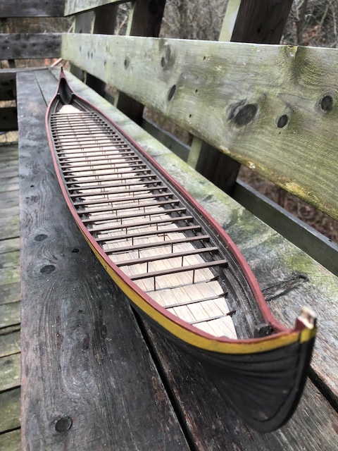
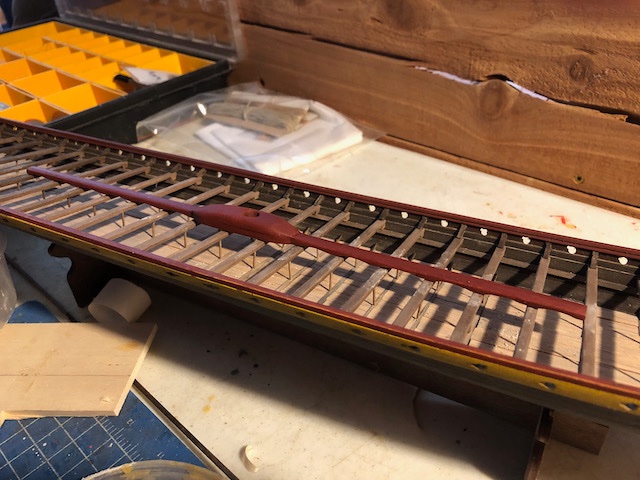
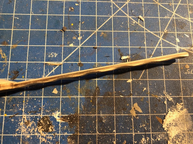
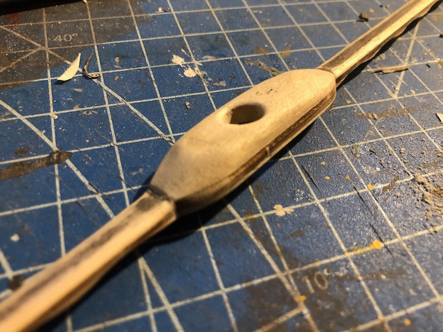
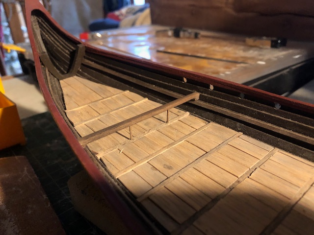
Started working on the mast foot, which is interesting in that it isn't attached to the deck, but rather runs atop the rowing benches for much of the hull's length. You can see a hint of this in the following Wikipedia image and a better view is in this link to a copyrighted photo: The kit's version is pretty simplistic, just two pieces of laminated plywood glued together with little shaping or detail. I decided to follow the reconstruction in making this more visually interesting. I also happened to lose the top piece, so made my own from scrap wood. I didn't try to match the prototype exactly, just went for a style I liked. For example, I shaped it to shed water on all sides rather than being planar on top. In addition, I liked the way the reproduction was arched along the bottom (between benches), so sanded in similar curves, which add nice visual interest: Here's the mast foot resting on the benches for testing purposes: And here it is painted a first shade of red: I'm going to weather this down from pure red, but you get the idea. I like the way it ties in with the cap rails, and the arching on the underside adds a subtle but attractive pattern between the benches. If you look closely at the last two photos, you can also see that I started adding braces connecting the top of the rowing benches with the hull. These are rough and simplistic compared to the real thing (see image linked here as well as the one linked above). I could have spent a lot of time trying to put in flowing curves and ensuring a perfect fit against the hull, but didn't. Part of this is that the hull, and thus the benches it supports, are somewhat irregular, so the end of each bench interacts with the shape of the clinkered planks differently, meaning that each brace would have to be independently carved to match its exact location at a rather small scale. Instead, I mass-manufactured simple triangle shapes and glued them in with some generic backing. They look great with a bit of distance, matching the rest of the model. I'm honestly a bit burned out on this project and ready to move on. So my standard is to improve on the kit but not go crazy for perfection or full accuracy. There are so many things I'd do differently if I were to do this kit again, but at this point am constrained by previous choices and errors so am just going for "looks cool to laypeople while not being totally offensive to experts". When I started this in July I did NOT expect it to be anywhere near as long or involved a project as it's turned out to be. I've done one side of these braces, so now need to do the 30 on the other side. Then I'll glue in the mast foot and decide what's next. Probably shaping the mast. Almost forgot, I've decided not to rivet the hull. Just don't have the interest or patience and am not convinced I can do it well enough to justify adding ~4000 more pieces to this kit. Most people won't know the difference and I'm putting some of that time into details that I think are more visually important (like all these braces along the interior hull, the improved mast foot, and so on). Sorry to the folks who were hoping I'd take the plunge. I'm open to it in a future project that's of higher overall quality. Thanks for sticking with me, and for all the encouragement.
- 323 replies
-
- 10
-

-
Fascinating. How does one go about restoring something like this while still retaining the "original", i.e. not using too much replacement material?
- 95 replies
-
- 6
-
-
- POW
- Bone model
- (and 2 more)
-
Good innovation. Wood definitely does not like to bend in two directions, one of the challenges for modeling in this way. I've done something similar in the past by creating a flat pattern for the amount of vertical bend, then clamping the soaked plank around that pattern. As it bends easily in the other direction, I found that getting some of the vertical bend locked in allowed the rest to happen naturally. Your method also looks promising.
-
Just measured the hull as roughly 32" long x 4.5" wide in Yankee-speak. The Dusek figures quoted above come out to 33.5" long x 14.5" wide. I don't know why the length is different, but I assume the Dusek width accounts for the yard, which would make the final presentation model a lot wider than just the hull (it's probably not the oars since they show them bundled). She's a beast. I'm actually wondering whether to put up the mast and sail or portray them stowed and furled to save some space.
-
Lovely work so far, keep it up.
-
That's a beautiful vessel and looks like a good choice to take the next step in your modeling skills. Looking forward to following your progress. Are you referring to the piece just right of the keel? It might be intended as a vertical clamp to be placed at either end of the keel to help stabilize it in that direction (not just from below). I haven't used this building slip, but for example see this image.
- 20 replies
-
- 1
-
-
- Le Renard
- Artesania Latina
- (and 1 more)
-
Looks like a good start. I'm not familiar with this kit, but the final product looks like a good level for a starter kit before tackling something more complex. Hope you'll keep us updated as you proceed!
-
Kris, I think many (most?) people, regardless of life situation, struggle to balance what they personally want (or are most interested in) with what works for their broader life, including loved ones. Your situation might make it more difficult in certain ways, but you're not alone or unique. So you have that going for you. Presumably your fiancé knows you and loves you, just like any fiancé (and vice versa) so really the question is how well the two of you can work out whatever differences you're going to have as your life together progresses. This model-time question may well be a good chance to start setting up a conflict-resolution system that works for both of you, because this won't be the last time you need it if you're as human as the rest of us. Mrs. Cathead and I have certainly spent a lot of time talking (and occasionally arguing) as we work out how best to share a life together. We each give up some of what we personally want because we're more important to each other than any of those activities. I'm sure you and your fiancé can do the same. For a hobby specific example, when I first got back into model-building, I set up my work area in a spare room in the basement, because it had a lot of room and let me play music and just "get away" in my own space. I assumed this was the best choice because it meant any mess or noise I made was out of the way. Turns out that doing so bothered Mrs. Cathead, because we otherwise spend most of our time together; we've worked together from home for over a decade, most of our living space is a single open-plan layout so we're almost never apart, and we share most intellectual interests. I thought I was giving her space, she thought I was withdrawing from her. So we compromised and I moved my working area to a small table in the corner of our living room. I gave up a significant amount of space, but added the enjoyment of being able to model while interacting with her and our house (for example, sharing the fun of seeing a hawk outside the window). Now we can talk, run ideas by each other, listen to the same music, etc. without being separated by my hobby. I actually like it way more than the old isolated workspace, but got there by giving up what I thought I initially wanted. In turn she accepts a slightly messy, sometimes ugly workspace that takes up space in our small main living area that could be put to other uses. I'm sure the two of you can work together to find a good solution. In my opinion, doing so is nearly the definition of "how to make a marriage work".
-
In addition to what the others said, I feel it comes down to whether both people in the relationship are being treated fairly. If she's getting the same amount of personal time that you are, to do whatever has value to her, then that's fair. If she isn't, it's not fair. It's helpful if spouses care about each others' interests (for both the interests and the quality of the marriage), but if that isn't the case, at the very least you both need equal time do to uninteresting things. But are there ways you can offer to involve her in what you're doing (with the equivalent offer to be involved in her hobby)? For example, Mrs. Cathead isn't deeply interested in modeling or maritime issues, but we enjoy talking over my projects and she often has good insights into decisions, methods, or final appearances as an outsider because she cares about me enough to care about what I care about. I do the same for her in areas that aren't my core interest (we do a lot of talking during garden-planning season because it helps her to run ideas past me even though it's very much "her" activity). Personally, I've never liked the way "Admiral" is used on MSW because it implies an imbalance in how people are treated in a relationship. Wives (most of us are men) are not, or should not be, considered some sort of bossy harpy forever getting in our way. You're equals, treat each other as such, and the rest should work itself out (or there are deeper problems that need addressing for which model-related issues are just a symptom). Ask yourself honestly if you're giving her the same free time and attention you expect from her, and go from there.
-
Great choice on the color. I certainly believe that, when fact is uncertain (and sometimes even when it isn’t), there’s room for artistry that improves a model’s visual appeal. After all, looking at it is part of the point!
-
That's an awfully complex way to make a hairbrush for your wife! Seriously, though, that's really cool.
- 179 replies
-
- 4
-
-

-
- longship
- Helga Holm
- (and 1 more)
-
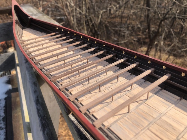
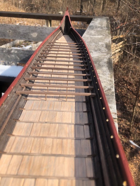
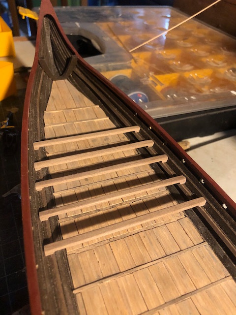
A quick update as things progress. I decided to add small knees to every deck beam, and am glad I did, as they do add quite a bit of subtle visual interest, tying together the deck and the hull. I then carried on with the rowing benches, now up to 13 out of 30. There are slight irregularities in the supporting posts, but these ships were built by hand and I bet they weren't machine-perfect either. Just need to make 17 more benches! I have my assembly line method pretty well worked out and make 2-4 at once depending on what time I have. This means there are subtle color variations in each batch of benches, but that also seems authentic to me. I'm going to weather them further in place anyway. Thanks for the comments and likes that keep me going. We just hosted my father-in-law's memorial service online this weekend, which was a huge amount of work (Mrs. Cathead and I developed a slideshow covering his life and coordinated something like 10 speakers and a much larger audience). Your support has helped me keep working on this through a very difficult time.
- 323 replies
-
- 13
-
-
That vertically movable rudder is really cool! Was that unique to Chinese ships? I don't think I've seen that elsewhere (not that I'm an expert).
-
Great job with the tape, makes very realistic iron. One suggestion on the rusting, I love using simple artists' pastels for that kind of weathering. You can easily get a cheap box of different colors at any art store, and hobby suppliers sell sets weathering pastels in subtler shades of color (I have one box that's all shades of red and brown and another that covers the black-white spectrum). They're very handy and add lots of texture to materials like wood, tape, and paper.
- 950 replies
-
- 2
-
-
- syren
- model shipways
- (and 1 more)
-
Chaperon by joep4567 - 1:48 - Sternwheeler
Cathead replied to joep4567's topic in - Build logs for subjects built 1801 - 1850
What don’t you like about it? -
Hello from Kansas City (Kansas side)!
Cathead replied to GGibson's topic in New member Introductions
Welcome from this Central Missourian and Royals fan! You've made an excellent choice in starting with simpler kits to learn skills before moving up the ladder. When you start a build log, let us know here as well so we can follow you over. -
Personally, I feel like individual planks always look better; the eye can distinguish a real gap from a fake one. However, that's obviously a lot more work. If you do decide to mark rather than cut, perhaps consider using a file to score a "gap" at each plank end that you then darken with pencil; that way there's at least a hint of three-dimensional joint there. It'll also be more consistent, as the eye will probably notice the difference between the actual junction on the long side and the fake junction at the short end. This is something you could practice on the reverse side of the veneer until you work out a method you like.
-
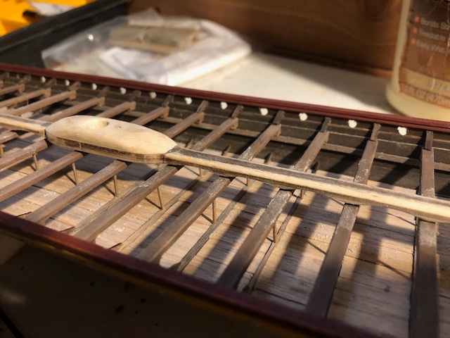
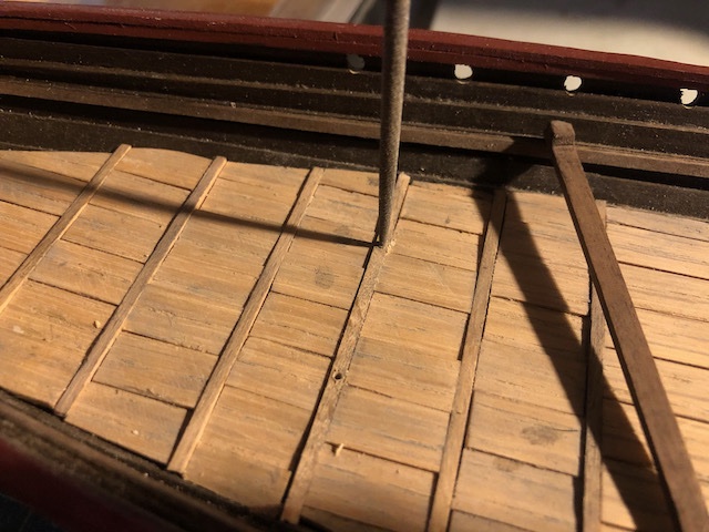
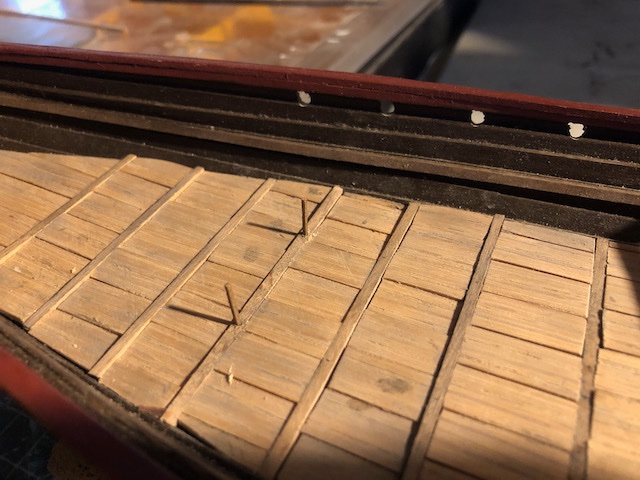
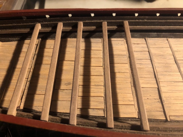
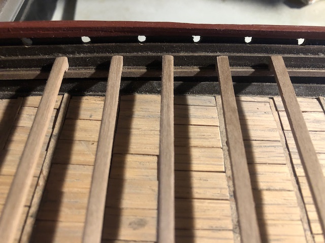
So what I'm doing is definitely a hybrid between the rather inaccurate kit and the "real" thing. For example, the kit has you place a long stringer along the inside of the hull as a bracket to support the benches on, which doesn't seem to appear on the real thing. I hadn't noticed that until after I'd installed it. Grumble. There should also be some kind of knees both above and below the benches. I definitely plan on adding the former, not sure I whether I want to mess with the latter. In addition to Petr's image above, see drawings here and here. I sort of wish I could go back and start over, I've been inconsistent in vacillating between making this a simple out-of-the-box build and a more involved, reasonably accurate, build. It's partly the tension between my goal for this build to be a relaxing project in a stressful time, and my inherent interest in learning about the actual prototypes and liking to get things "right". I think this is a learning first build, and maybe someday I'll go back and build another one with more attention to detail from the beginning. Certainly, my first steamboat was nothing to write home about compared to later efforts. So all that being said, I'm just going to press forward with what makes me happy and not crazy. In this regard, I started playing with making the bench support posts, as these add a lot of visual interest and aren't too fussy. I started by carefully marking each post location, in a straight line along the hull's long axis, based on a good estimate of where they're shown on the drawings and reproduction. Then, one bench at a time, I drilled holes and widened them slightly with a round file: I then took a very thin piece of square stock (pre-stained dark brown) and cut two appropriate lengths, then filed one end just enough to slip into the holes: As the hull isn't uniform, these need slight adjustment for each bench. The goal is for them to just touch the underside of the bench. First example resting in place: First five: Nothing's glued, just test-fitting. Also notice that I stained the benches and darkened them with black pastel. I think I like how these look. They're not turned into the fancy spindle pattern you see in the drawings, but I'm not doing that. Now I have to decide if I'm going to add any deck-level knees, as those would have to go in before the benches. Will think it over. Getting the angles right could be really fussy, and they'll be somewhat hidden below the benches. But the supports definitely add visual interest and a more logical appearance (nobody would expect those benches to stretch that far with mo support), and are already an upgrade to the kit. Thanks for sticking with me.
-
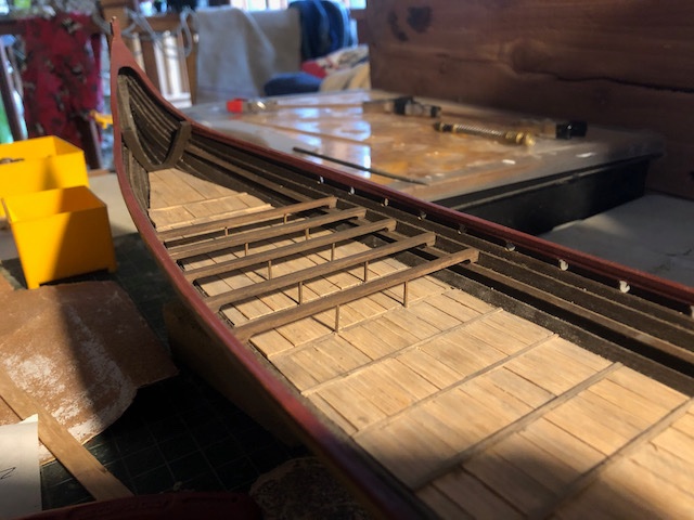
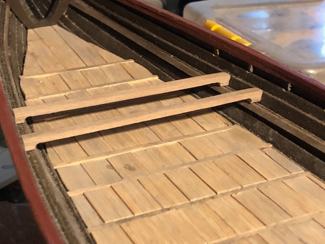
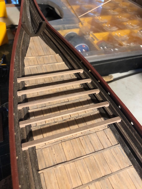
I decided to move on with the rowing benches. The kit's version of these is really simplistic, while the reproduction's are far more interesting. The kit just wants you to lay rectangular planks with no other bracing, like this (from the Dusek website): But I want to do better than that. On the reproduction, you can see various other details, such as knees connecting the benches with the hull, the rounded surface of the benches, and the thin posts supporting the benches from the deck. It's hard to find photos of the reproduction's interior; the best ones I can find are part of a copyrighted stock photo collection, so I won't embed them here. But this and this are representative of the look I want to replicate. My first challenge was that adding my own wooden deck raised the deck surface quite a bit, given its thickness relative to the kit's paper-thin insert. So if I rested the benches on the bracing added by the kit's instructions, they'd be too low. In addition, since I raised the hull's sides a bit, the benches would also be too low relative to the gunwale. I could have added more bracing all the way along the hull, but decided that an easier and interesting-looking way would be to raise each bench individually, also making this build a bit more unique. Here are the first two test benches: I simply cut and glued two small pieces of the bench material at each end, then sanded them into an attractive curve where they join the bench. This raises the bench top to about the same height above the deck as a modern seat would be (slightly lower, but then again people were shorter 1000 years ago). I think it looks cool. Notice that this also raises the bench surface right to the next interior strake, making it easier to add knees later on (no need to notch each knee over a plank joint). Encouraged by this, I did three more: In the above photo, note that the right-hand two haven't yet been sanded into their rounded shape. This shows how much proper rounding adds; the square planks (a la the kit version) just don't look right to me. Here's another view of the difference: And here are two views of five fully finished benches: So far, so good, I think. If you looked closely at the stock photos linked above, you'll notice thin posts supporting the benches from the cross-beams in the deck. I'm going to need to integrate those into the benches as I install them, as it'll be a huge pain getting them just right if I try to do it after all the benches are glued in. So right now the benches are just resting there. But that's a detail I definitely want to include. I'll keep working on these, assuming someone doesn't see a major flaw in this plan! 5 down, 25 to go.
-
Larry, there were other ways to stow the shields for a voyage than lashing them to the rail. I'm with Steven, shields in that position would seem more hindrance than help in most normal operation. Also keep in mind that Viking shields were not actually that strong; they were thin wood held together by a single brace in the middle and generally a leather (not metal) rim. They were designed to absorb impact, not live forever. So it seems to me that the horizontal forces of wind or waves levering on one of these thin shields, partly wedged in a shield rack or otherwise lashed on, would more likely lead to the shield breaking. And I'd guess that the Vikings cared more about having intact shields upon reaching their destination than getting a bit wetter and colder than they already were. The few references I know of to shields being set up this way tends to imply it being done for show rather than for function.
-
I'm no expert, but leaving the ports open (and the oars/rudder in the boat) seem like reasonable examples of modeler's license for improved visual appeal. After all, in various other ways the model probably won't resemble the ship in an exactly accurate operational state, so why worry about these small details?
- 950 replies
-
- 2
-
-
- syren
- model shipways
- (and 1 more)
-
Those are really helpful shots. It seems very clear now that the basic problem is not enough twist in that plank. As someone mentioned, those are thicker planks than one often sees (possibly because they're balsa), and that probably is making it harder for them to take the twist naturally.
-
I'll repeat from your earlier question thread, I really think you need to properly bend the planks using soaking and/or heat. Your plank looks like it is bowing away from the bulkhead when it should be sitting tight against it. At a minimum, when you glue them on you should be clamping them so that each plank's surface is fully in contact with the bulkhead. Prebending them makes this much easier as it reduces stress on the glue joint. In the vertical photo you give above, the plank is properly sitting against the lower (in the photo's orientation) bulkhead. But when it continues up toward the next bulkhead, it maintains its orientation from the lower bulkhead rather than twisting to make proper contact with the next one up (note that the inner edge sits against the bulkhead next to the previous plank, but the outer edge veers away to form a wide gap). That's a problem that is best solved by properly bending the plank. Most hulls require this sort of thing due to their complex 3D geometry. As also mentioned in your last thread, tapering the plank could also help, though the instructions you showed made no mention of this common practice, so I'd suggest trying bending first as this is reversible and repeatable (unlike tapering). It's hard to say this in written words, so if you're not sure what I mean, I can try to come up with a visual example.