kurtvd19
-
Posts
3,015 -
Joined
-
Last visited
Content Type
Profiles
Forums
Gallery
Events
Everything posted by kurtvd19
-
 Elijah: Welcome to the NRG. Mary processed your membership this morning. Look for your membership card in the mail. Kurt
- 701 replies
-
- 4
-

-
- phantom
- model shipways
- (and 1 more)
-
Elijah: Good start. The string idea works well. You have connected the line on deck and the line along the keel, stem and stern. You need to make sure that with these lines connected that the centerline at the bow and stern are both parallel. You can check this by leveling the hull port to starboard and lock in place with some heavy objects on each side so it does not move unintentionally. Using a square or something else that will sit perpendicular to the table top make sure the line at the bow and at the stern are both also perpendicular to the table top. A building board would be the perfect way to hold and align the hull while you do this. I sent you a PDF on building boards and I know your tools and materials are limited but the data will show you how a building board works and you can improvise a similar arrangement. Hope this helps. Kurt
- 701 replies
-
- 6
-
-
- phantom
- model shipways
- (and 1 more)
-
Your build log should go in the Kit Model Builds section rather than in the Scratch Build section - other wise I agree with Cathead and look forward to following your project. Kurt
-
Soldering dangerously close to the hull
kurtvd19 replied to popeye2sea's topic in Metal Work, Soldering and Metal Fittings
I didn't know it was a plastic hull. I think you need to figure out a way to get the chain parts off the hull. Supposedly resistance soldering can be done on HO train rail ends with plastic ties w/o damage to the ties but I wouldn't want to take a chance with a plastic hull. Kurt -
Soldering dangerously close to the hull
kurtvd19 replied to popeye2sea's topic in Metal Work, Soldering and Metal Fittings
If you use a torch that close to the hull, PLEASE have a fire extinguisher handy. I can see needing to form the chains in place, but surely you can remove them to do the soldering. One thing that can work is resistance soldering - a thin insulator between the chain and the hull would be adequate to protect the hull from the heat. Resistance soldering gets the metal between the electrodes hot extremely quickly and the electrodes act as heat sinks with the power off. My torch is growing cob webs since I started using a resistance soldering unit again. Had used a home made one 20 years ago but when my buddy moved we flipped and he got to take it with him. Stay Brite - a silver bearing solder strong enough for chain plates, etc works good with a resistance soldering unit. Kurt -
Mark: You can include the ships boats in the main build log. You are displaying the ships boats off the model but most builds include the ships boats as part of the build and not done in separate logs. If you include similar wording as the undelined wording noting that the ships boats are included - HMS Tremendous with Ships Boats - it covers the whole project. You can also do separate build logs but I think those following the project would want to go to only one log to follow your progress. Really it's your choice. Kurt
-
Elijah: Sal had real good advice to plan ahead. I always recommend a careful reading of the instructions before you start anything and then to keep looking ahead for things that might be better done a bit sooner. As an example, some part installed at step 5 might be in the way of step 7 so look ahead to see that you will have access for step 7. Glad to see you have a good start. Kurt
- 701 replies
-
- 8
-
-
- phantom
- model shipways
- (and 1 more)
-
Help with Model Shipways kit choice
kurtvd19 replied to Bill Gormley's topic in Wood ship model kits
Bill: Check the NRG's Resources lists for model clubs in NJ Kurt http://www.thenrg.org/modeling-clubs.php -
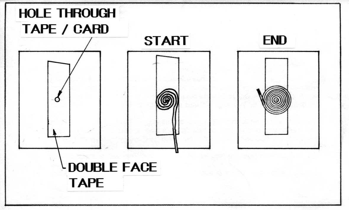
Chris: Use an index card or anything of similar size and a piece of double side tape. Poke a hole through the tape and card. Insert the end of the line through the hole, sticking the line down to the card as shown and wind the coil pressing the line down onto the tape. When the coil is the size you want, stop coiling and "paint" the rope coil with diluted white glue. Let it dry and remove from the card/tape. You can make multiple coils at the same time by using additional strips of tape. Kurt

-
Geoff: Nice work. For the next Ships on Deck (January - December's strictly party) bring some of these photos on a flash drive so the rest of the club can see your work. Kurt
-
Cathead: Great work. Between your build and Glenn's I spend too much time admiring your work - need to get some time in on my projects but you guys are distracting me. Keep it up! Kurt
-
Cathead, you guessed right. Click on the link below to see Glenn's work. Glen talked at the 2014 NRG Conference in St. Louis on this wreck and their work. Kurt http://nautarch.tamu.edu/model/
-
I agree that after several kits one has less need for good instructions. This is why I encourage new modelers here to stick to the US manufactured kits for several builds before they turn to the Italian stuff where the instructions are inadequate at best. With a couple of builds under one's belt there is a much better chance of being able to make sense of the very poorly written/translated instruction in those kits. But, this is a newer modeler asking for advice who doesn't have the experience that will enable him to just use the plans and/or photos. Kurt
-
Too bad Midwest has stopped production of their kits - I recommended them to beginners all the time because of the instructions. Bluejackets instructions are very good - and if you find an error (as I did) they correct the error in future printings - that's true customer service. The newer Model Shipway kits have very good instructions. That said, almost any kit can be found with something lacking in the instructions. But that's what MSW is for - ask if you are not sure as it is easier to ask here than undo glue of remake a part. The Italian kit instructions are horrible. I watched the guy at Mamoli in Milan who was doing the English instructions for a kit look up each word in an Italian to English Dictionary and write it down. I had just been introduced to him via a translator as he spoke NO English and I spoke no Italian, but then I wasn't doing a translation! Mantua's are not much better in my opinion but a couple of the people there did speak enough English that we didn't need a translator. Kurt
-
Les: Look into the Weller model WLC100. It is adjustable and the actual pencil iron is replaceable as well as the tips. I purchased the WLC100 a year ago and use it a lot. Check out this link to Paul Budzik's video on soldering. The unit he uses is very expensive commercial version similar to the WLC100. http://paulbudzik.com/tools-techniques/Soldering/soldering.html Kurt
- 1 reply
-
- 5
-
-
Jigs for soldering photo etch
kurtvd19 replied to bluenose2's topic in Metal Work, Soldering and Metal Fittings
Les: Check out the video by Paul Budzik on soldering techniques. I have done a lot of silver soldering but hadn't done much with photo etch and a soldering iron (except electrical connections for R/C boats) and his video helped a lot - so did getting a good adjustable soldering iron similar to the one he uses but a few steps down in $$ - a Weller WC100. Kurt http://paulbudzik.com/tools-techniques/Soldering/soldering.html -
Ken: I am on board for this build too. Your first was so good this one should be something special. Kurt
-
Gerald: While there isn't a specific heading for steel ships the build log of your model would be of great interest to a lot of us. Don't worry about leaving out tools as there will be a lot of interest in them too. Your work will be followed when you post it. I have been checking your web site ever since you asked about the bilge pumps. Kurt
-
Spray painting
kurtvd19 replied to Jaydee37's topic in Painting, finishing and weathering products and techniques
Experience with it yes - on a model no. Several years ago I used it to do a touch up job on a fire truck fender. It worked fine for that job (the pin striping repair was another issue) and the results are equal to a spray can finish - that is to say, not as good as an airbrush. If you can do a decent job with a spray can you can expect similar results with this item but it's only advantage over a rattle can is the ability to use whatever color you need rather than what might be available in a stock rattle can. I can't recommend this over an airbrush as you have no control over the spray pattern - just like a rattle can. An airbrush is the way to go for model painting. We don't usually paint areas big enough to need a spray bigger than an airbrush delivers and we most often are painting small areas that are better painted with an airbrush with a lot less masking needed. Kurt -
2015 NRG Conference Update - MYSTIC
kurtvd19 replied to Chuck's topic in NAUTICAL RESEARCH GUILD - News & Information
We were also shocked at their meeting room rental prices compared to their other rates and to other places nearby. The 2006 NRG Conference was held there - under former ownership. We are still pretty darn close to the Museum and the conference hotel is closer to the entertainment and dining area od downtown SD from what Mike tells me. Kurt -
2015 NRG Conference Update - MYSTIC
kurtvd19 replied to Chuck's topic in NAUTICAL RESEARCH GUILD - News & Information
Yeah they are high - like 10X what we can afford for meeting space! Kurt -
2015 NRG Conference Update - MYSTIC
kurtvd19 replied to Chuck's topic in NAUTICAL RESEARCH GUILD - News & Information
San Diego on October 6-7-8, 2016. Conference hotel is the Downtown Double Tree right up the hill within easy walking distance from the San Diego Maritime Museum. Kurt -
Hal: Welcome to the hobby. Don't try to cut through the piece in one cut. Take a light cut and then go over it several times to cut through the piece. If it's a thick piece, cut outside the line and then sand the edge to the line to avoid any tendency to angle your cut. Another thing to watch out for is the wood grain and the tendency of a blade to follow the grain - again light cuts will help to avoid this problem. If you are having a problem with the wood splitting along the grain and taking off a part of the piece you are making, make cuts across the grain first so that the tendency of wood to split along the grain doesn't affect your cut. This is something that will get easier with more experience. But be sure to use only SHARP blades. If the blade dulls either replace it or hone the edge - a sharp blade is a safe blade while a dull blade will not cut the wood well and can and will slip and cut you just fine. Kurt
-
Model Shipways Willie L. Bennett Questions
kurtvd19 replied to FlounderFillet5's topic in Wood ship model kits
Marcus: The NRG Journals are preserved in their entirety on CD's that we sell - see the NRG Store on the NRG web site. We have every issue up to the last ten years available on the CD's with a new CD to be done next year at the conclusion of the next issue of the Journal that will include the last ten years. We also sell copies of many of the articles on the NRG web site for $2.50 each as PDF's that one can download and save to your hard drive. We are getting more articles up but due to a possible switch to the (internal - nobody will notice the switch) operating system of the NRG web site we are holding off putting more articles up to the web site as the webmaster doesn't want or need to do everything 2X. Once the change is made we will continue to post additional articles. Unfortunately the article you want isn't one of the articles now posted. It is a good article and I used it when I built the WEB several years ago. Send me a PM and I will email a copy of the PDF to you. Kurt -
Glen: Another great model in the making. I am avidly following your posts. After hearing your presentation at the 2015 NRG Conference in St. Louis on the Heroine I was hoping you would post your work on the model here. Thanks for sharing with us. Kurt