


Roger Pellett
-
Posts
4,519 -
Joined
-
Last visited
Content Type
Profiles
Forums
Gallery
Events
Posts posted by Roger Pellett
-
-
Gary, great job on the boat in general and the winch in particular. Your subtle use of colors, and simulation of wear really adds interest. The winch looks like a piece of equipment used by men who depended on it to make a living - used but not abused.
Roger
- FriedClams, ccoyle and mtaylor
-
 3
3
-
Steve, Nice work on an unusual subject. Does this eventually become part of the railroad layout that appears in the background?
Roger
- FriedClams, mtaylor and Canute
-
3
-
-
Three Points
The most detailed information on windlasses that I know is contained in Howard Chapelle’s book American Fishing Schooners. This book is in two parts- the first discusses the development of the ships. The second is an extensive “glossary” complete with sketches, drawings and period catalog cuts of construction details and fittings. The entry about windlasses is particularly extensive.
The most successful of the improvements to the handspike windlass was the Armstrong Patent Windlass that Incorprated ratchets to allow up and down motion via pump handles. I don’t know exactly when this improvement was patented but you might be able to track down the patent on the Internet. The Schooner Alvin Clark built in the 1840’s and sunk in the 1860’s on Lake Michigan was found by modern day salvagers to be fitted with an Armstrong Patent Windlass.
The Armstrong Patent Windlass did not require massive iron castings. The small lever and ratchet system could and was used with wooden barrel and whelps throughout the Nineteenth Century.
Roger
-
Yup
In the late 1960's there was a fight between the Director, Division of Naval Reactors, US Atomic Energy Commission, aka Admiral Rickover and the McNanara DOD systems analysis people to determine if future large attack carriers would be nuclear powered. This took place during the development of the two reactor Nimitz class carrier.
Congress sided with Rickover, mandating that future capital ships (carriers) would be nuclear powered. Carl Vinson was a key member of the Senate Armed Forces Committee.
I was a very junior Naval Officer serving in Rickover's Naval Reactors organization when this happened.
Roger
- mtaylor, lmagna, John Allen and 1 other
-
4
-
Blame this all on Admiral Rickover, who in the struggle to increase the number of nuclear attack submarines, which had been previously named for fish famously said "fish don't vote."
Roger
- John Allen, Canute, lmagna and 1 other
-
4
-
A true scroll saw or what I call a jig saw stretches the blade between upper and lower attachment points. It is therefore possible to load the blade with considerable tension keeping it rigid during the up and down cutting strokes. This allows the use of very fine, thin blades. With inadequate tension the blade buckles on the down stroke and soon breaks.
If this saw is built like an upside down Sabre saw without an upper attachment there is no way to tension the blade and rigidity must be provided by the blade itself. This means that you will be limited to thick blades with sufficient depth to withstand the cantelever bending loads as they do their work.
Roger
-
The dirigible hanger at Moffit field is a duplicate of the one at Akron, Ohio. According to the internet the Moffit field hanger has been stripped of it’s siding and is to be restored by Google. Both hangers (Moffit and Akron) were designed by Dr Arnstein, a German structural engineer hired from the German Zeppelin Co by Akron, Ohio’s Goodyear Zeppelin Co. Dr. Arnstein was also responsible for structural design of the Akron and Macon.
For my First Class Midshipman Cruise during the summer of 1964, I was aboard a minesweeper homeported at Sasebo, Japan. If my memory is correct we used MPC when going ashore. I know that I used MPC somewhere and the only other foreign station I visited during 4 years of Navy active duty was 2-3 days at Subic Bay, Philippines that same summer.
Roger
- Canute, popeye the sailor, lmagna and 2 others
-
5
-
Paul,
Most research of Baltimore Clipper type Sailing vessel’s was conducted by Naval Architect and Maritime historian. Chapelle based his research on drawings of American built vessels that he found in the British Admiralty Archives. The ships had been either captured or purchased by the Royal Navy. He published the results of his research in a series of books. Chapelle died in 1975 so his work is “old” but still relevant.
Two books deal extensively with Baltimore Clipper type craft; The Baltimore Clipper, first published in the 1930’s, and The History of American Sailing Ships. Both are inexpensive and readily available on used book sites. Both include plans for Dos Amigos. I suggest that you buy one or both to supplement the kit information.
The heart of any ship model is accurate depiction of hull form. The current Pride of Baltimore is the second vessel of that name- built to replace the original that sank in the Caribbean. In designing this replacement vessel Naval Architect Thomas Gilmer changed hull shape below the waterline to improve stability. While she appears to be a Baltimore Clipper to the visiting public, below the waterline her hull lines are more “yacht like.” I therefore suggest that you build the model as Dos Amigos.
Roger
-
Justin,
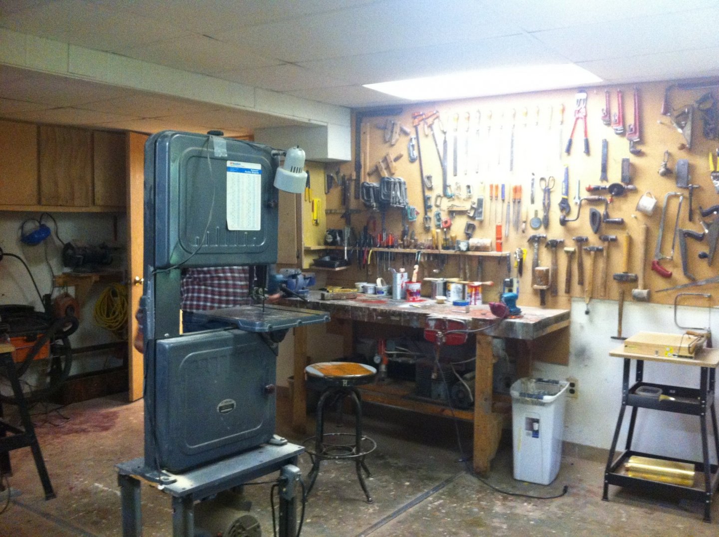
If you only have room for one workbench that will be used for model making, fixing kids bikes, and miscellaneous honey do chores my MDF top will not be durable enough. I have another larger workbench also in my shop for rough work. It has a flush mounted woodworkers vice and a large machinists vice. The bench top is made from 2in x 6in construction lumber laid edge to edge topped with a piece of 3/4in particle board screwed down with sheet rock screws.
The bench has accumulated 30 years of battle scars, spilled paint, etc and could be renewed by replacing the particle board top but there are a lot of great memories caught up in those battle scars so I decided to leave it alone.
 Another thing that you might want to add is an organized way of keeping your hands clean. While this may sound silly it has taken me 50 years to learn this. In this regard the kitchen table modelers have an advantage over modelers working in a garage or basement because they are next to a source of soap and water. In my case a combination paper towel holder and shelf
for holding a pump bottle of proprietary hand cleaner.
Roger
-
This for me is a timely question as I am just putting the finishing touches on remodeling my workshop including a dedicated workstation for ship model building. I am fortunate to have space for a heavy duty workbench too so this is just intended for light duty detailed work. All of my models are scratch built and this may affect some of my preferences.
When our house was built the builder built a rough desk in the basement where the house plans could be spread out. He left it for me when the house was finished. The desk measured 48x30in. I used it as built for many years but recently decided to improve it. In doing so I had the following objectives:
1. Provide a smooth, flat, and level work surface.
2. Provide surfaces easy to clean.
3. Minimize clutter.
4. Provide pleasant surroundings where I want to spend time.
Bench Top: The desk was originally surfaced with rough construction grade plywood that was not flat and could not be kept clean. I further damaged it by driving screws into it to secure jigs and fixtures. I replaced the top with one made from 1/2in MDF. The top is fastened to a “ladder frame” made from 2in x 4in construction lumber planed flat on my jointer. The top/ladder frame is balanced to ensure that it stays flat.
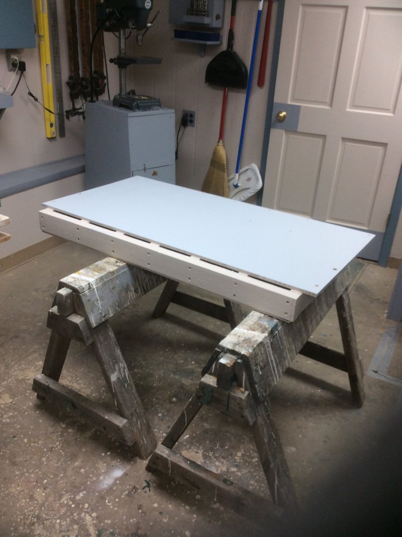
Not apparent in the photo is a grid of brass inserts screwed into the top. The inserts are each drilled and tapped for a 1/4in-20 machine screw allowing me to secure jigs, honing strop, miter box etc without damaging the top. When not in use each insert is plugged with a slotted head set screw. The top sits in a frame in the desk and is level and flat.
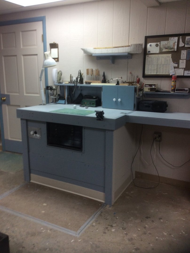
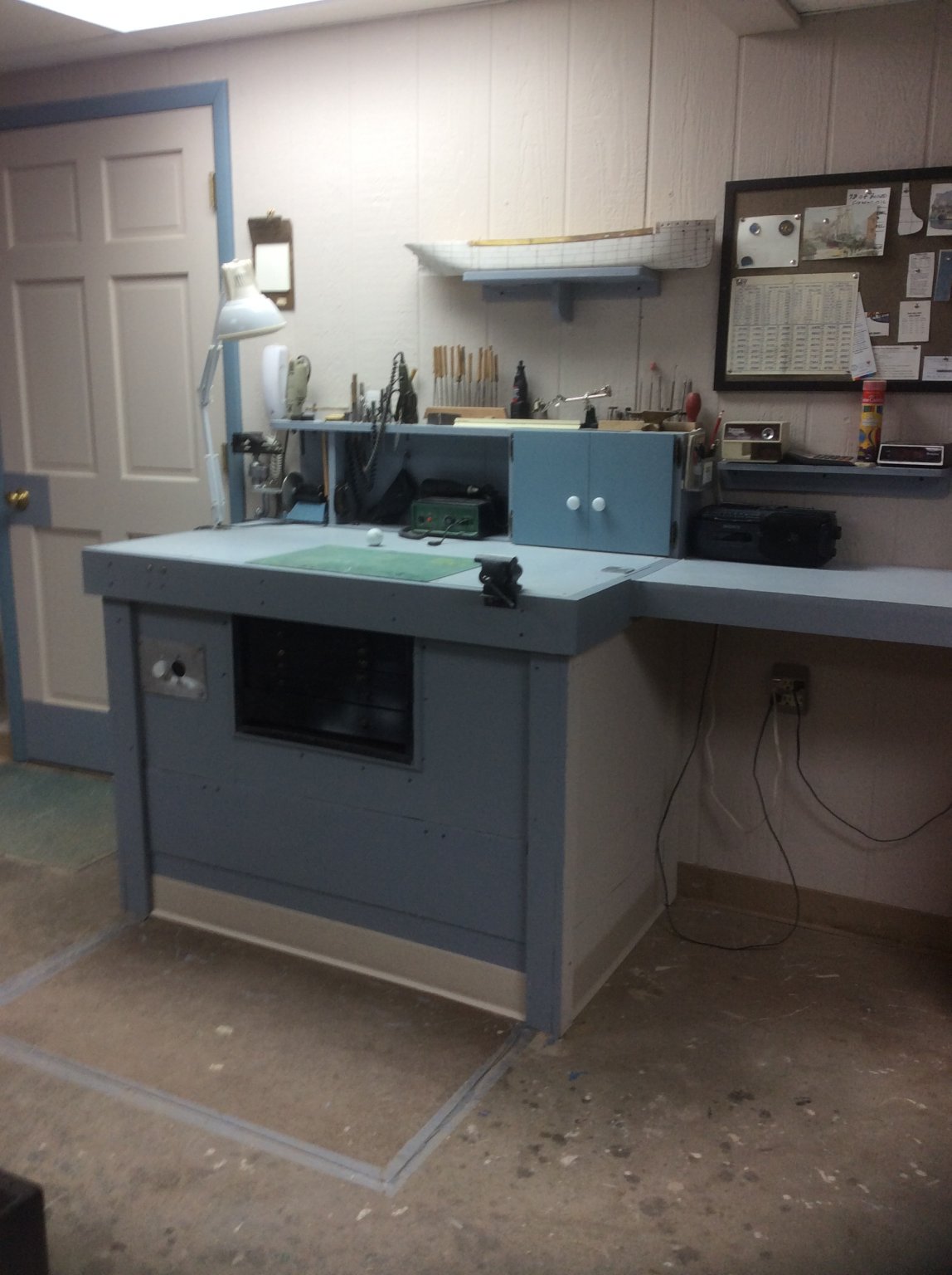
Here is the finished work station: The Aluminum panel on the lower left is my speed control for my rotary tool and Jarmac disc sander.It can also be used foe soldering iron temperature control. It is nothing more that a household light dimmer wire.d to a dedicated socket. The adjustable lamp can be easily mounted on either side of the bench. The Aluminum pad reinforcing the unused
mounting hole is visible on the right hand side of the bench top. There are brass inserts at the left side of the bench front for mounting my swivel vise, now in it’s storage position at the back left corner. The cupboard stores clutter like my two boxes of small clamps and my numbered drills that I always seem to be knocking off an open shelf. I don’t play golf. The golf ball was borrowed from my son as a final flatness/level check
- druxey, Canute, Ryland Craze and 5 others
-
8
-
Yes, I read somewhere that boat designers using a particular CAD proprietary hull lines program were complaining that all of their designs came out of the program looking like a J-26 (a popular American racing keel boat).
Roger
- FriedClams, Bob Cleek and mtaylor
-
3
-
Bob’s post above is right on and explains why it is impossible to build as some have claimed, the “definitive” model of any wooden ship. Using the same table of offsets, no two drawings or full scale patterns from the mould loft made by different individuals will be exactly the same. This is because of the decisions made by individuals when plotting and fairing lines. I even doubt if the same individual could produce the exact same drawing twice as he will make slightly different decisions each time.
While CAD offers a high degree of precision, I’m not sure that it is any better at transferring offset dimensions into the definitive hull shape because it too must make decisions when plotting curves. I’m not sure that you the user know what those decisions are or if you agree with them.
Using offsets taken from a model or builder’s draught, you do not know what changes, minor or otherwise were made in the mould loft, adding another degree of uncertainty. This also may account for the fact that different vessels built from the same plans perform differently, eg; The large 44gun American Frigates Constitution, United States, and President all had different sailing characteristics.
Your aim should be to produce a model that faithfully reproduces the characteristics of the real thing while realizing that slight variations are to be expected.
Roger
- mtaylor, FriedClams, michael mott and 1 other
-
4
-
Scow Schooners were also common on the Great Lakes. Both rectangular sailing barges and a more sophisticated hard chine pointed bow type. A number of these have been investigated by nautical archeologists. Look on the Internet. Specifically, historian Pat Labadie wrote a paper describing one sunk off Kelly’s Island in Lake Erie. I bought a. Copy on Amazon. A number of years ago, someone wrote an article about building a model of one the pointed bow scows in the Nautical Research Journal. Plans were from the National Watercraft Collection. The best discussion of scow Schooners and their regional differences that I am aware of is in Howard Chapelle’s “American Small Sailing Craft.
Roger
-
-
Probably a silly question, but since airplane models are not my thing, “inquiring minds want to know.” What was the actual experience in combat of gunners on board bombers downing enemy aircraft?
Roger
-
Lou,
The hanger in your post is the Moffit Field one with it’s siding removed. Apparently Google has committed to residing it. The Akron, Ohio hanger is the same design.
Roger
-
There is a huge zeppelin hanger at the Akron, Ohio Municipal Airport. It was built to house the airships Akron and Macon that were built there by Goodyear Aircraft. The rubber companies that were headquartered in Akron were interested in the Navy’s attempt to build lighter than air rigid airships because of the possible application of rubberized fabrics. Goodyear also hired the German Zeppelin Company’s structural expert, Dr Karl Arnstein. Dr Arnstein designed and Goodyear built the Aluminum mast for the L. Francis Herreshoff designed J. Boat Whirlwind- in the 1930’s the aircraft companies were the experts in designing and building Aluminum structures.
There is a sister to the Akron hanger at Moffit Field, Mountain View California. Both hangers are over 1100ft long and unlike the Santa Anna and Lakehurst hangers feature orange peel doors that open on a circular track folding back flush with the building side walls. This was considered to cause less turbulence than the flat sliding doors, making it easier to move the airships in and out of the hanger.
Both the Akron, Ohio and Moffit field hangers supposedly still exist. Moffit Field is leased by Google and my Son-In-Law works for them in New York but travels to their West Coast headquarters. He told me that when he was there this fall he saw the hanger.
I’ve never seen an airship but as a child growing up in Akron saw dozens of blimps as Goodyear still built them throughout the 50’s
Roger
- lmagna, mtaylor, popeye the sailor and 2 others
-
5
-
Large wooden vessels, especially large Schooners continued to be built in American and Canadian shipyards into the 20th Century. Many large wooden Schooners and steamships were built in American yards during the World War 1 shipping crisis although most were completed too late to be of use. The technology used to build them is discussed in Charles Desmond’s Wooden Ship-Building, first published in 1919.
It is my understanding that Charles Davis worked in yards building these wooden ships and this experience influenced his understanding of much earlier wooden ship construction.
Roger
-
A number of years ago there was an article in the Nautical Research Journal by a highly regarded British ship modeler (sorry, I don’t remember who) about modeling beyond the limits of available research. The point of his article was that the extent of and level of detail should be limited to known information. The example that he gave was that a model of the Mary Rose should be limited to a pair of mastheads and tops sticking out of the water. This was before the vessel’s remains had been extensively studied.
His point was well taken. Why build a plank on frame model with exposed framing if you know nothing about the original vessels construction details? Instead of building a wholly fictional model of the Lexington build a model of another Bermuda built vessel of the same era- Chapman’s Bermuda built sloop. But don’t show exposed framing based on dubious information. Exhibit your craftsmanship by fully planking it.
Roger
-
There is information that is becoming available from the Nautical Archeology people. Several Revolutionary era vessels have been excavated in Penobscot, Maine. I believe that the most complete is the brig Defense (or maybe Defiance?)
The regularly spaced doubled framing shown by Davis is much later American practice. There is some archeological evidence that for small vessels in merchant serrvice, floors and futtocks were not necessarily connected to each other.
Roger
- uss frolick, mtaylor and druxey
-
3
-
As I have posted before, my favorite is Durham’s Rock Hard Water Putty. (I have no connection with the company.). It is a light tan powder, that you mix with water to the desired consistency. It dries quickly, seems to bond with most everything and sands easily to a feather edge. It is also foolproof. It hardens regardless of how thick or thin it is mixed. I buy it at our local big box home improvement store.
Roger
- Duanelaker and mtaylor
-
2
-
Brown poster paint powder can be used to color some fillers.
Roger
-
Gary,
A great job! What drives the winch?
Roger
- mtaylor, FriedClams and Moab
-
3


Naparima by Kevin Kenny - FINISHED
in - Build logs for subjects built 1901 - Present Day
Posted
Kevin, Nice work! If you look up the thread “simulated rivets on plastic hull” on the forum, you will find my magnum opus regarding riveted hulls based on observations of surviving examples around the Duluth Harbor.
Overall conclusions- Rivets joining hull plating are barely visible since they were usually hammered flush into a countersunk hole. This was necessary to take advantage of the hot metal of the rivet shrinking to produce a watertight joint. Rivets joining topside structure are more prominent as snap rivets with domed heads were used to join light superstructure plating.
Roger