


Roger Pellett
-
Posts
4,519 -
Joined
-
Last visited
Content Type
Profiles
Forums
Gallery
Events
Posts posted by Roger Pellett
-
-
-
Since you are mixing your own colors you might consider adding just a touch of brown to your black Bitumen paint. Also, you can scale down your colors by adding a little neutral grey. The idea is to reproduce the effect of looking at the real boat from a distance. For example, looking at a 1:48 scale model from a distance of 1 ft is equivalent to looking at the real thing from a distance of 48ft.
Roger
-
American ships- Wooden. Mystic Seaport has a mast hoop shop demonstrating how these were made.
Roger
- mtaylor, 3DShipWright and allanyed
-
 3
3
-
C is definitely the horse for of the fore sail sheet. The circular arc allows the sail to cross over without releasing the sheet when the boat is tacked; a self tacking sail.
A could be a support for a swivel gun, temporarily installed by the carpenter as Bruce has posted. There appears to be another of these near the bow.
B is much more problematic, A wild *** guess. I wonder if it is a pump. The Longboat was the ship’s boat with the largest cubic capacity. It was, therefore, favored for hauling the huge quantities of water needed by crews on a high salt diet. As an all wooden boat it would float even if nearly full of water. While this was often carried in barrels, I have seen old seamanship texts where the plug in the boat’s bottom could be removed to allow the boat to fill with fresh water. The water filled Longboat was then towed by the other boats to the ship. The pump would have been used to transfer water to tanks or barrels aboard ship.
Rollers, fore and aft. These are for lines used to handle anchors, anchor buoys etc. This gets into discussions of Longboat vs launch. Beaudroit (Sp) says that British anchor handling practices differed from French as the British lifted heavy weights over the bow instead of the stern as the French did. British Longboats, therefore featured full lines forward and fine lines aft. French Longboats had much fuller lines aft and used stern davits. The introduction of the Launch into the RN changed this. Launches had much fuller lines aft that allowed handling of heavy weights over the stern and davits.
Roger
-
-
The Shop Notes article that Bob mentions is a slightly abbreviated version of one published in about 1990 by maritime history researcher and professional model builder Eric Ronnberg. As far is I am concerned it is the definitive word on actual Nineteenth Century paint colors and how to “miniaturize” them for ship models. The article includes color chips. Highly recommended!
Roger
-
When it comes to eye hand coordination I have always been at or near the bottom of the pack and neuropathy hasn’t improved things. However. Like many modelers, for miniature woodworking, I own a 1/8in and 1/16in chisel. I seldom use them. I find that a chisel with a wide blade is easier for me to control. IF I was to cut a chamfer I would reach for my trusty Stanley yellow handle 3/8in chisel. The wide blade is easier to roll as necessary and it is far less likely to wind up where I don’t want it to be. Of course, keep the chisel sharp and if possible try to cut with the grain.
Roger
-
-
These river boats were painted with cheap readily available colors. Bitumen is of course petroleum based tar, a byproduct of reducing coal to coke. It would have been used for tar paper on upper level decks not subject to foot traffic. White would have been white lead. Bright (expensive) colors would have been in applications intended to attract customers. Model railroad colors should be fine.
BTW, MSW has A resident riverboat expert. He hangs out on the Scratch Built Models 1850-1900 area under the name Cathead. He knows many times more about Western Rivers Steamboats than all of the European kit companies put together. Look up one or more of his outstanding models.
Roger
-
I have easily cut 1/32” hard brass sheet with my Byrnes Saw. I should add that it helps to lubricate the blade. I have some sprayable dry lubricant that works well. The Byrnes saw uses the exact same blades as machine tools do. Unfortunately you cannot control the speed of the blade like you do with machine tools. Also, as you are using blades without “set” to the teeth you need to make sure that your fence is aligned well.
Roger
-
My system for producing brass strip:
1. Starting raw material: I like the “hobby sized” pieces of of brass sheet; approximately 3”x7”. This should be hard or at least half-hard. Do not anneal.
2. Glue this to a similar sized piece of wood. Match the edges of the plywood and brass. A piece of 1/2 in plywood is ideal. For glue, I like Elmer’s Probond Advanced glue. This is a PVA type glue intended for use on multiple porous and non-porous materials. It seems to have good shear strength but poor peel strength. Like all PVA glues it benefits from high clamping pressure.
3. Mount the blade with the highest tooth count on your table saw. If you have a mini table saw (Byrnes, Preac, etc. ) better yet. Set blade height slightly higher than the thickness of the brass. You will not be cutting clear through the wood. Set your rip fence and saw your strip.
4. Any slight roughness or burr can be easily cleaned up with sandpaper on a block of wood.
5. You should now be able to easily peel the strip from the wood backing. It helps to work the edge of an Xacto knife under a corner. Once you have an end loose, the strip seems to pop off.
This will produce a nice clean cut without curling.
Roger
- mtaylor, Mirabell61, Matt D and 3 others
-
6
-
-
-
Seamanship! The crew lived in an era where they were still expected to be able to solve all sorts of problems with simple machines; levers block and tackles, etc. So, this tackle could have been used for any number of different things. Was the tackle permanent? What had the vessel been doing when the photo was taken? Answering these questions might be the key to solving the mystery
Roger
-
Johnny,
A friendly suggestion: I suggest that you forego rivets, plate seams, and just finish the hull smooth with a nice paint job. There are two different reasons for my suggestion-
First, hull plating rivets were driven hot into a tapered hole. As they cooled, they shrunk drawing the plates tightly together. It was important that the rivets completely fill the tapered holes to provide enough force for tight joints. A big lump of material left on the outside of the hull was evidence of a sloppy job. At most modeling scales, rivets would be next to invisible. (The prominent dome head rivets seen on model railroads are “snap head” rivets used on light gauge steel.)
If you want to show rivets and scribed plating lines, you need to know the type of plating system used. The usual plating system was the “in and out” method where each “in” strake was lapped on each side by its adjacent “out” strakes. If this method were used to plate Gorch Foch’s hull then you would not see scribed lines but lapped plates. There was also a flush riveted plating system used on very high end work like yachts. This was very expensive as all seams had to be backed up on the inside of the hull with metal strips.
The second reason has to do with all of those brass airports. These are not realistic as in large steel hulled vessels, the brass air ports butt against the inside of the hull so all that you would see on the outside of the hull is a hole in the plating. Never less, the model’s builder chose brass eyelets. Your model therefore becomes something like one of the handsome models made by builders of steamships in the early 1900’s with their bright brass fittings. The convention for these models was smooth hulls.
It’s of course your model, being restored in your Dockyard but I suggest that a smooth hull and a nice matt paint job would produce a more appropriate result.
Roger
-
For many of us building wooden ship models is as much an enjoyable intellectual activity as is “working with your hands” as my wife calls it. This approach can affect your tool selection. I grew up in the era when model kits; ships and airplanes, did not come with instructions; just parts and and one or more drawings.
I would assemble a very minimal set of tools- Xacto knife, miniature plane, needle files, sandpaper, PVA glue, a set of Zona razor saws ( these often come with a mini miter box.), a small metal engineer’s scale and a GOOD small bench vice. Buy whatever kit you plan to build, read the instructions, and get busy. You will soon be presented with problems to figure out. That’s where the fun comes in as you will discover tools that you need and don’t have to solve the problem. This is especially true of clamps as ships have a lot of peculiar geometry that requires innovative solutions. Buy these tools as you need them.
Drilling- I would not buy any kind of motorized drilling device at this time. A high speed Dremel tool can quickly destroy soft wooden parts supplied with kits. Start with a set of #60-80 high speed (not carbide!!) Drill bits and a pin vise.
Read MSW build logs. You will discover a lot of innovative solutions. A lot of them do not require expensive hobby shop tools.
Roger
-
I dug out my Snow Squall Book and found that I was wrong. No single museum wanted the entire piece that was salvaged so the bow section was cut into two pieces; one going to the Maine Maritime Museum, the other to the museum in San Francisco. The waterway piece went to NYC South Street Seaport.
Roger
-
Since I don’t built models from kits, I haven’t been following this, but WOW everything about this model is exceptional! In my opinion, this belongs in the scratch built category since you are making every.thing yourself. IMHO 1:96 is a difficult scale to provide your level of detail. Well done!
I too have read the Snow Squall book. My recollection is that once she was salvaged, there was some squabbling over the pieces vs who really was equipped to properly conserve and display them. The result was a King Solomon decision to send different parts to different organizations. Rather sad.
Roger
-
When I was a child, a friend and I enjoyed playing with “Britain’s” lead toy soldiers. At $2.00 per box, they were unimaginably expensive but they were right up there with Lionel trains, another luxury item, on my Christmas List. When I outgrew them, my mother packed them carefully and saved them for me. As an adult, from time to time I have enjoyed painting 54mm military figures, so I decided to unpack my Britain’s figures to add to my display.
Upon doing so, I discovered that the heads had separated from the bodies. 1950’s era Britains soldiers are not properly proportioned in that they are much more slender than real people, particularly their necks. My mother’s careful packing had restricted air circulation, and their necks had corroded. Easily repaired with wire and a touch of Epoxy.
Roger
- Canute, thibaultron, catopower and 1 other
-
4
-
Quote
I hope that the State of Texas can find a proper home for her complete with a climate controlled visitors center that can display fragile artifacts and properly interpret her significance. Federal involvement means National Park Service requires that she fit into some “thread” in American history. These threads are largely social and ignore unique engineering accomplishments. Participating in two World Wars and being the only first generation dreadnought in the world won’t cut it.
Roger.
-
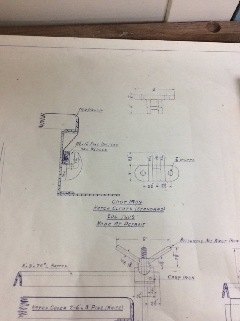
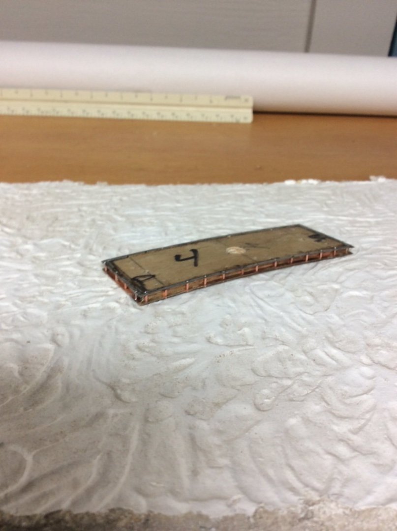
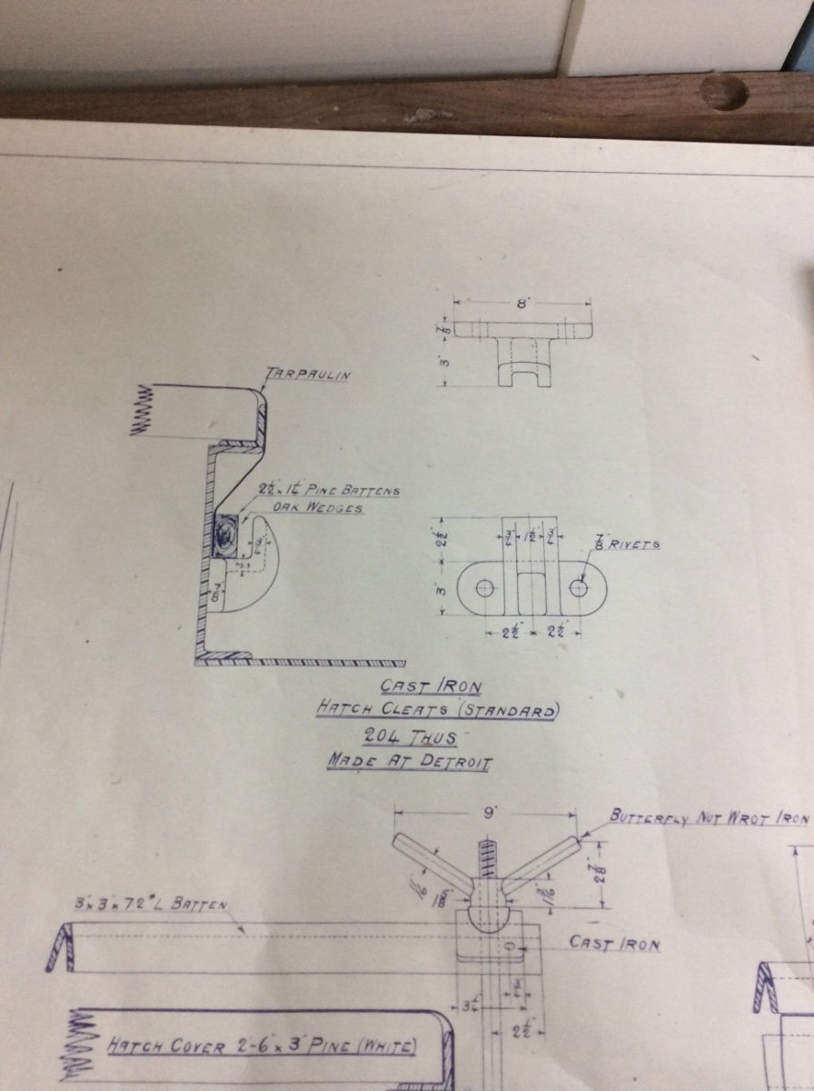
Hatch Coamings
Benjamin Noble’s main deck was pierced by openings for six hatches, not seven as claimed by some writers. The seventh hatch sits atop the after deckhouse to provide access to the coal bunkers. The hatch openings were surrounded and reinforced by a 1ft high coaming made from channel section with the athwartship sides rolled to match the deck camber. Cast iron clips were riveted to the channel on 30in centers to hold a wooden batten. The batten and wooden wedges secured heavy tarpaulins used when bad weather threatened. The hatch covers were wooden to be discussed in a future post.
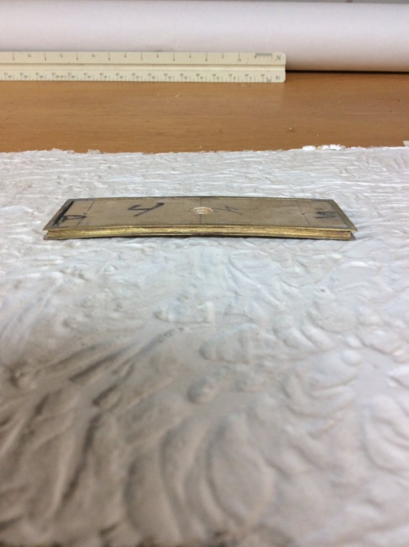
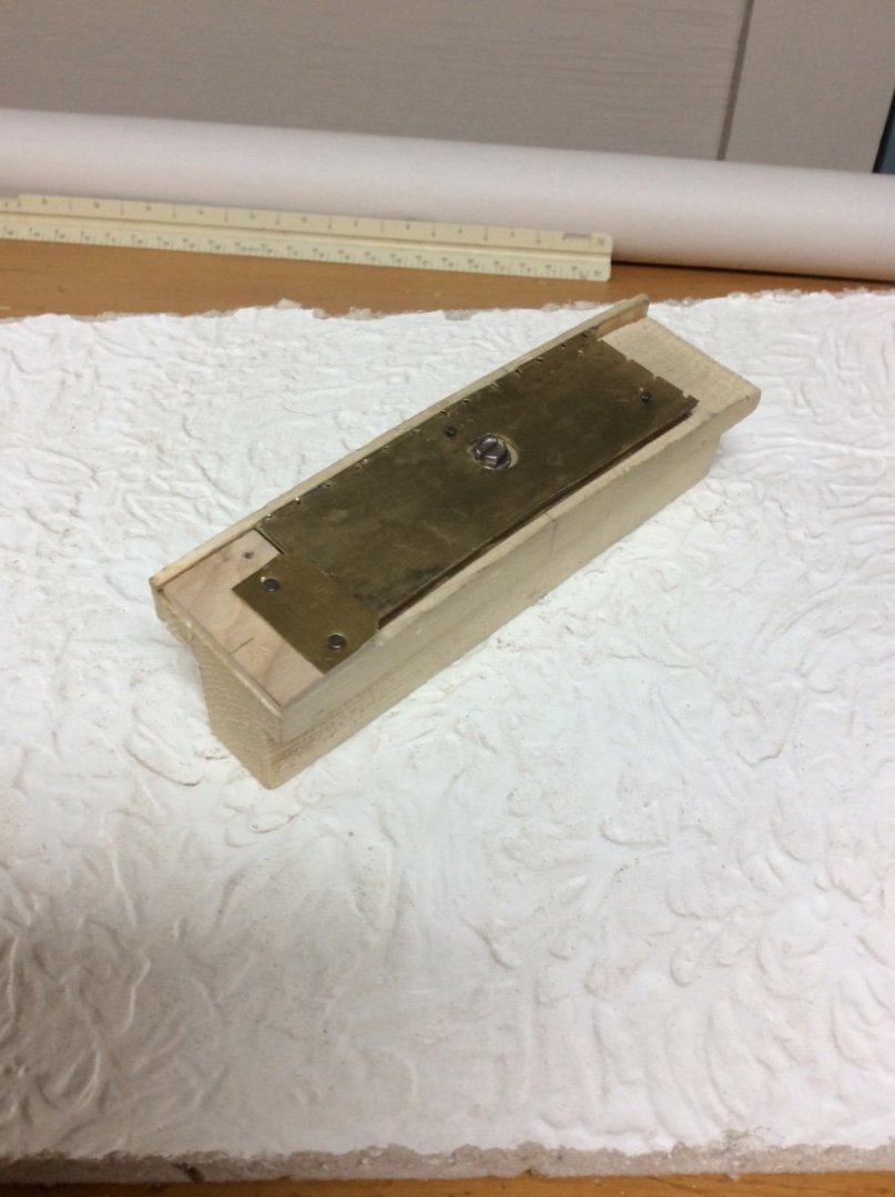
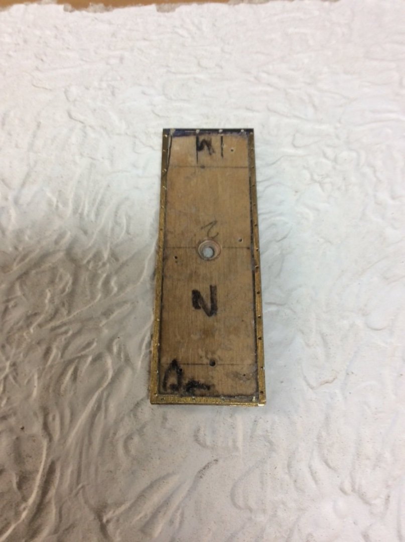
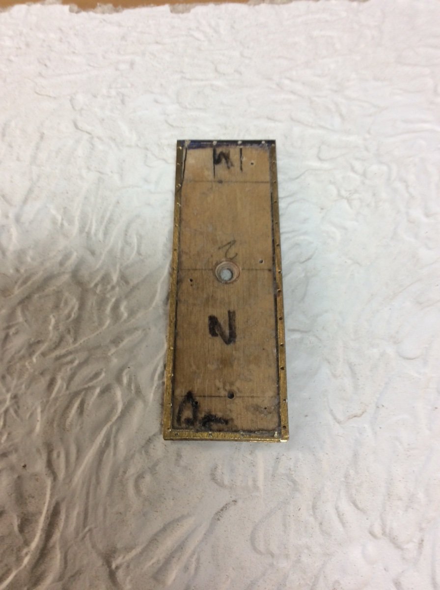
The coamings were made several years ago during one my previous attempts to model the ship. Construction was straightforward. The channel shapes were cut from 1/8in square brass tube on my Byrnes saw and bent to the correct camber around a wooden form. With the large bend radius the channel section did not distort. The pieces were then cut to length. A Zona fine tooth razor Saw works well for this. Brass angles were also cut to reinforce the joints and the assembly was soldered together. A wooden insert epoxied inside each coaming will allow the assemblies to be mechanically fastened to the deck and will provide a glue friendly surface for the hatch covers.
The long main decks of these Lake freighters often provide little of interest so when I dug the previously made coamings out of my stash, I decided to add detail to the hatches by modeling the clips. At 1:96 these clips are tiny and I tried several approaches. Attaching photo etched parts with CA glue does not appeal to me and I wanted to avoid the look that the coaming “needed a shave” with pieces of bent wire sprouting out. I finally decided in an impressionistic approach by soldering pieces of 24 gauge square wire at the correct spacing vertically within the open channel section. This involved drilling correctly spaced 1/32in holes vertically through both channel flanges, feeding the wire through the holes and soldering it in place. A sheet metal pattern and wooden fixture clamped in the vice for the Sherline milling column/ sensitive drilling attachment made drilling vertical correctly spaced holes possible although several drills were broken in the process. While this by no means matches the actual clips it is a neat appearance that will be enhanced when the coamings are painted.
-
I believe that there are, or at least used to be, one or more trains in Canada that will carry peoples’ boats into wilderness areas.
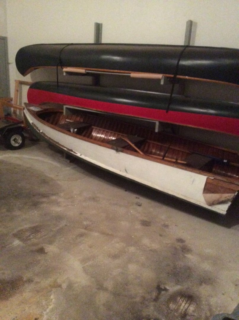
The first canoe that I restored was a Shell Lake (Wisconsin) that I got in trade for a Folbot kayak. It was a freight canoe with National Forest Service markings stamped into the keel. I sold it a number of years ago.
Old wood canvas canoes have an interesting history. Old Town was just one of many builders and there were many variations. They are also a joy to paddle. Unfortunately, I can no longer lift them for transport.
Roger.
- Cathead, Keith Black, mtaylor and 5 others
-
8
-
Very nice work as usual Eric.
I have two Old Town canoes that I restored a number of years ago. The first is a 1916 Charles River. My sister belongs to a canoe club in Pittsburgh started by Westinghouse Employees over 100 years ago. Someone dumped the canoe off in the weeds next to the clubhouse. My sister told me to take it before it was burned in the spring cleanup. Restoration bordered on Abe Lincoln’s story about his father’s axe. New handle, new head, but it’s still my father’s axe.
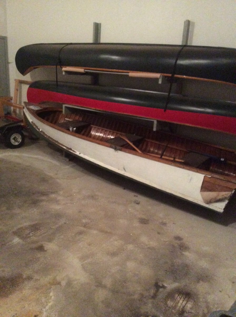
The second is a 1944 OTCA. I traced it back to a camp in upstate New York that was the inspiration for the movie Dirty Dancing. Old Town wood canvas canoes are all stamped with unique serial numbers and production records are available on line. Restoration was easier; replacement of several broken ribs, some planking, new canvas, and fixing some rot. Photo below.
How does the Amtrak shuttle work? I can’t imagine loading the boat on the train.
Roger
- Harvey Golden, mbp521, GrandpaPhil and 7 others
-
10
-
The metric “equivalent” to 1:48 is 1:50. I wonder if Shapeway’s figures sold as 1:48 are actually 1:50?
BTW, that guy emerging from the hatch carrying the cartridge is about to get decapitated by the guy firing the mortar!😆
Roger
- thibaultron, Old Collingwood, Canute and 3 others
-
5
-
 1
1


Long boat pedestals
in Discussion for a Ship's Deck Furniture, Guns, boats and other Fittings
Posted
B could also be a removal bitt for towing another vessel.
Roger