


Roger Pellett
-
Posts
4,519 -
Joined
-
Last visited
Content Type
Profiles
Forums
Gallery
Events
Posts posted by Roger Pellett
-
-
The simple answer to your question is that a well built drill press that has been reasonably well taken care of should last a lifetime. Mine is coming up on 60 years.
A more complicated question is whether spending $300 for this makes sense. Like most things, it depends. If you are just assembling model kits, I see little need for a drill press. If you have more ambitious projects in mind then you need to consider the size of the table and height under the drilling head. In this case, bigger is better and I would not buy a mini tool. I use my drill press most days that I am working in my shop, but my project, a 1909 era steel lake freighter is somewhat of an outlier. Since the topsides are soldered brass, I am constantly making jigs from craft plywood and aluminum to hold brass pieces in place for soldering and this requires many drilled hoes. For drilling tiny holes in brass parts, I use a sensitive drilling attachment fitted to my Sherline milling column.
If I were spending $300 I would look for a quality full sized used drill press; Rockwell, Delta, etc. OR, I would spend $100 for a Menards general purpose house brand drill press and save the remaining $200 for Sherline tools at a later date
Roger
-
It’s a really nice model, well researched, and beautifully displayed. If you as the master Shipwright declare it finished, that’s good enough for me. Leave it alone!
Roger
- JesseLee, Louie da fly, Ferrus Manus and 1 other
-
 4
4
-
The steam bent construction that Bob describes was used particularly in Downeast New England to produce cheap serviceable working craft. The famous Friendship Sloops were built with steam bent frames toe nailed into the keel without floor timbers.
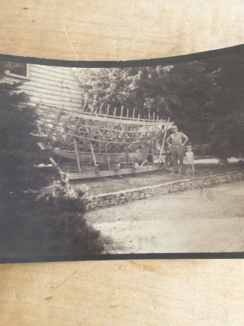
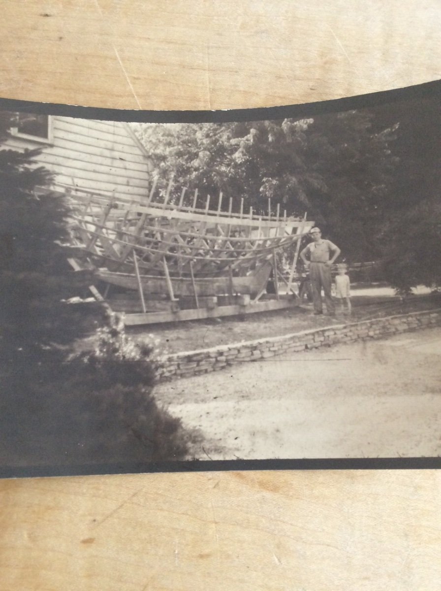
The picture below of me “supervising” my father building an L. Francis Herreshoff H-23 sloop back in the late 1940’s illustrates a major reason for using this building process. It reduces and simplifies the lofting required. Instead of lofting each frame, bevels, etc. only the major longitudinal structural elements, the transom and some widely spaced moulds need to be drawn. It likewise simplifies construction. It is POB construction in 1:1 scale. The ribbands and moulds were of course later removed. Unlike the Friendship Sloops, Herreshoff did specify that each frame be fastened to a sawn floor. This particular boat took my mother and father and sometimes me cruising in all kinds of weather on Lake Erie and was still being sailed by a different owner into the mid 1960’s.
Howard Chapelle was a proponent of adapting traditional working craft designs for affordable pleasure boats. His early work was done during the Depression. By adapting this construction method to the Pinky hull form he produced a boat that could be built by amateur builders like my father. This does not mean that someone did not take Chapelle’s design and loft it for sawn frame construction. It also means that your choosing to build this model with sawn does not make it less authentic.
Roger
-
Glen,
That punch that Mike posted will also work on sheet brass. .005,”,.010”, and .0145 in thick material is available at hobby shops and some hardware and home improvement stores. Aluminum flashing material will work too. If you use. Wood, try to find some 1/64” thick model makers plywood.
Roger
-
Duco cement is great for temporarily gluing metal to wood. Duco is the old model airplane cement.
- mtaylor, Glen McGuire and Keith Black
-
3
-
Looking at your photo, it would appear that there is one of two possibilities. Either the gage is defective or there is something blocking the inlet to the gage. This raises two more questions. How did the factory set max working pressure per note on the machine and is the pressure switch functioning properly? I don’t see how you could have done anything to affect the operation of the machine. If you can manually lift the relief valve, do that and see what happens.
Roger
- Canute, mtaylor, thibaultron and 1 other
-
4
-
If I were fixing this, using a razor saw or other fine toothed saw I would cut away the damaged area. I would cut vertically down from the deck and horizontally in from the bow. This will form a step to seat a wooden block. Regular lumberyard pine would be my choice. The block will eventually be glued in place with ordinary PVA glue but first while the block is still square I would dry fit it and drill for a dowel. Using a French curve I would extend the curve of the deck and vertical shape of the bow on to the block. Away from the model I would cut the block to its vertical and horizontal shape slightly outside of the traced lines. The block can now be doweled, glued in place and shaped using conventional methods.
Finishing is just a matter of finding something compatible with what’s already there. I suspect regular hardware store gloss black enamel. Not acrylic. Rust-Oleum makes a nice black inanely in a half pint tin.
Roger
-
-
I’m defenitely looking forward to following this. Fire up the angle grinder!
- mtaylor, Old Collingwood, Ferrus Manus and 1 other
-
3
-
 1
1
-
-
-
The great Naval Architect Nathaniel Herreshoff designed all of his yachts using half models that he carved. These half models were finished with shellac. Today they are 100-130 years old. They are now displayed on the wall of Herreshoff’s reconstructed office at the Herreshoff museum in Bristol, RI. Attendees at the 2019 NRG Conference were fortunate to be admitted to this usually closed room to see these models close up. The shellac finish has held up well.
Roger
-
Many years ago I bought an old used Sears Metal Lathe. Not the nice kind made by Atlas, one considerably older. I think that I paid about $100. The woman that sold it to me, said “My husband said that he was going to use it to build a bedroom suite!” I’ll try to use that line of reasoning some time. 🤣
Roger
-
-
Wives fail to understand (or choose not to understand) that fixing things around the house or yard work, now disguised as “gardening” and Ship Modeling are not interchangeable. For example, “You’re so good at working with your hands, why won’t you fix that toilet?”
Roger
- Keith Black, Wintergreen, mtaylor and 6 others
-
3
-
6
-
Keith,
I second Gary’s notebook idea. As the shipmodeling world continues to move towards 3-D modeling and computerized fabrication of parts, your building style will become a (sadly) lost art.
Roger
- Keith Black, Retired guy, FriedClams and 1 other
-
4
-
Patrick,
I remember several years ago when you began this model and were shaping the hull with an angle grinder thinking, “This isn’t going to turn out well!”🤣 Was I ever wrong. Your skill, perseverance, and intellectual curiosity has produced a beautiful and historically plausible model. Well done!
I have enjoyed following your progress and am looking forward to Mary Rose.
Roger
- mtaylor, Baker and Edwardkenway
-
2
-
 1
1
-
I am NOT criticizing the quality of the kit or the enjoyment that casual hobbyists might get from assembling it. I am criticizing marketing it as Santa Maria Boat. If we don’t have reliable design information for Santa Maria, even less is known about the small boats that she may or may not have carried. There is some scholarship coming from the excavation of the “Red Bay Galleon” found in Newfoundland. Accurate drawings exist for one of her whaleboats and a more typical small boat called a “Barca” has been excavated but I have been unable to find anything published about this boat. These boats are also 100 years later than the boat in the model kit. A c1570 Spanish whaleboat unfortunately has nowhere near the marketing appeal as Santa Maria.
Roger
- Chuck Seiler, thibaultron and Baker
-
3
-
Fincham’s descriptions should be viewed as an individual point in time Data point rather than an all encompassing description. For example:
Longboats rather than launches were used by the Royal Navy for the better part of the Eighteenth Century; prior to Fincham.
According to May (The Boats of Men of War) clinker, ie. lapstrake boats were not favored by forces afloat as they were difficult to repair. There were carvel built cutters. In fact by 1900 the US Navy standard drawings show only carvel construction.
Roger
-
Luis, There is currently a thread on the Painting Topic here on MSW that also relates to this. As you have discovered gluing wood to metal is difficult with uncertain long term results. I find that sometimes even Epoxy does not bond well. My idea posted on the Painting Topic is to simulate copper sheathing with paper, suitably colored. This can be glued to the hull with ordinary PVA woodworking glue, provided you can get rid of the rubber cement residue.
Roger
-
-
Wefalck’s post above suggested another train of thought. How were these caps made and how did it affect their design? As there does not appear to be any functional or structural reason for parallel vs perpendicular caps manufacturing processes must have played a role.
Casting- By casting, a part of virtually any shape could be formed. The process requires, however, a skilled pattern maker, a skilled foundry man, and an iron foundry. If the part were cast then the term “iron” refers to cast iron which is an alloy of iron and carbon; very high carbon. Cast iron has poor ductility. It fractures suddenly rather then deforms. Cast parts often have interior voids that further weaken them. In the Nineteenth Century, inspection techniques capable of finding these voids did not exist.
Castings would have been expensive, perhaps needing to be imported, and structurally less than ideal.
Forging (blacksmithing) - If the mast cap were perpendicular to the lower and top masts, the cap could be easily hammered up from wrought iron strip by a blacksmith working in the shipyard. A forged cap intended to be parallel to the waterline with the angled holes would be difficult if not impossible to make in a simple shipyard blacksmith shop from wrought iron strip. Keep in mind that the only welding process available was “forge welding”; heating the two pieces to a high temperature and hammering them together. Depending on geometry welds could be subjected to a load (proof) test, but like castings, other inspection and testing methods were not available. Some joints could be secured instead by riveting. Wrought iron would have been an excellent material for this application it’s stringy microstructure makes it tough. Ship structures made from wrought iron (SS Great Britain) have stood up remarkably well in the maritime environment.
Forged wrought iron caps would have been inexpensive, and within the capability of the local shipyard. While welds could have been a problem these caps would have been structurally sound. Welding could be avoided by riveting. Fabrication techniques would have limited geometry.
This analysis favors caps perpendicular to the masts.
Roger
- BANYAN, mtaylor and Keith Black
-
2
-
1
-
-
New Hyundai HY7524 compressor not working
in Modeling tools and Workshop Equipment
Posted
Glad to hear that the problem was easily solved!