


Roger Pellett
-
Posts
4,519 -
Joined
-
Last visited
Content Type
Profiles
Forums
Gallery
Events
Posts posted by Roger Pellett
-
-
-
I use an air brush for general ship model painting. I’m not into shading striping or other more sophisticated techniques. I am currently using my second Badger 350 airbrush. The first one I damaged by over pressurizing and salvaged most of its parts. It is a simple, rugged, easy to disassemble and clean tool. The “guts” come in three varieties; coarse, medium, and fine. It is relatively inexpensive. It will spray thinned acrylic paints.
IMHO a regulated air supply makes an air brush viable, and that requires a small compressor with an air tank and pressure regulator. Over the years, I have tried all sorts of setups ranging from canned air (completely inadequate) to a homemade shop air system. I now use a small compressor/ tank combination similar to the pancake air nailer compressor that Tim mentions above. These are sold for use with air driven carpentry tools so they are compact and portable. They can often be found on sale for less than $100US.
Roger
-
-
I personally do not like to criticize others work on this forum. Everyone is trying to do their best. In this case, you have asked for opinions, guidance, so here is mine.
Your sails are neatly made.
The cloth that your sails are made from is overscale. At any reasonable modeling scale in scale sail cloth would be at most, a few thousands of an inch thick. Furling these sails will emphasize the over scale appearance as you will wind up with a fat lumpy roll.
For real sails, the stitches viewed at a “scale distance” joining the panels together would be invisible. The seam between the panels would be a continuous faint line.
If if you do want to show the model with furled sails, use a much thinner material that will produce a tight seaman like roll. I would suggest silkspan.
Roger
- mtaylor, Mike Reader and allanyed
-
 3
3
-
Very Nice work !
If you want to have a model Lightning to sail, the WoodenBoat store used to offer a kit. The kit featured a deep keel protruding from where the centerboard would be on the real thing. There was a lead weight on the bottom of the keel.
A true to scale model of a Lightning would apparently lack both lateral resistance and transverse stability to sail well.
Roger
-
I built a POF model of the 1812 era New York Pilot Boat Anna Maria many years ago. I used Howard Chapelle drawings that I adapted for use with the Harold Hahn method.
It is my experience that it is not necessary to bevel sawed out frames before they are erected. It is also much easier to bevel them after erection when the shape of the entire hull becomes apparent. The keel, stem, and sternpost should be installed first to stabilize the structure.
Harold Hahn did not bevel frames before hand on his earliest models. He adopted this step later as a labor saving step.
Roger
-
-
Here in the US, our big box home improvement stores sell imported bench top drill presses for less than half what you are planning for a Proxxon Hobby drill press.
A drill press is actually a simple tool. If I were you before spending $200+ (US) I would shop around and see what’s available. I personally would avoid one with electronic speed control. I prefer belt driven tools. If the electronics fails, you can be faced with an expensive repair. IMHO electronic variable speed control is often added to tools to increase market appeal but provides little utility. I can change spindle speeds on my belt driven drill press by moving the belt to different sheaves but rarely do so.
Whatever you buy check to see that it is equipped with ball or roller bearings, and that the column and table provide rigidity.
A possible advantage of the Proxxon tool might be its ability to accept smaller drills used in model building. The chuck on my drill press will not close on drill bits with diameters less than 2mm. This limitation is easily overcome bu mounting the drill bit in a pin vice and mounting the pin vice in the drill press chuck.
As an ex-owner of several boats, both sail and power, the old saying was that if you added “Marine” to the description of a product it automatically cost much more. It would seem that the same is also true of tools marked “Hobby.”
Roger
-
The current network of natural gas pipelines was a latecomer to many parts of the upper Midwest; I believe 1960’s. The whaleback steamship, SS Meteor spent the Post War Years as a member of the Cleveland Tankers Fleet delivering refined petroleum around the lakes. This job is now performed by pipelines and tanker trucks.
So, coal used to have many uses. The railroads burned huge amounts of coal. Many towns had synthetic gas plants that gasified coal for domestic uses. Coal was also burnt directly as a heating fuel. In the Twentieth Century, coal was the principal fuel used to generate electricity. Coal was also the dominate fuel used for steamships on the Great Lakes. The last coal fired bulk carriers retired around 1990, and the ferry SS Badger that sails from Manitowoc to Luddington, MI still burns coal.
C. Reiss used to be a major coal distributor on the Great Lakes. The massive coal loading docks capable of turning an entire Railroad hopper car upside down to dump its load into a ship still exist at Sandusky, and Ashtabula, Ohio. Since they maintained a dock at Sheboygan the Brown Hoists are probably theirs.
Great quantities of coal are still shipped over the lakes but the pattern has changed from East to West to West to East. The Coal loading terminal in Superior Wisconsin annually ships coal delivered by dedicated unit train from Wyoming to customers along the lower lakes.
Roger
- mtaylor, thibaultron and John Fox III
-
3
-
IMHO, the attraction of this model is its graceful lines. In attempting to accurately redraw these lines to the inside of the frames it is easy to distort this shape. Maybe the magic of CAD eliminates this concern but I’ll leave that to others.
Roger
-
Zero clearance inserts are not hard to make as needed. Use either thin model makers plywood or aluminum. You can use the one that comes with the saw as a pattern. The slot is cut be installing the blank insert and slowly raising the blade.
- Canute, mtaylor and thibaultron
-
3
-
-
John,
The following are suppositions based on my knowledge of late Nineteenth Century Great Lakes trade, not the Port of Sheboygan in particular.
Lumber was a “Downbound” cargo. It was loaded in small backwater ports in undeveloped areas of the Northwoods and unloaded in growing midwestern cities like Chicago and Detroit. It was usually unloaded by hand. It is therefore, unlikely that a small port like Sheboygan would have had mechanized ship unloaders to unload lumber.
The machinery in your photos are Brown Hoists, mechanized ship unloaders patented in 1884, Patent 300,689. These were designed to unload cargos of Iron Ore. So, what is happening in your pictures?
1. Would there be any reason to be unloading Iron Ore in Sheboygan? Was there a basic steel industry nearby? It would seem that the answer to these questions is no.
2. Coal was in 1884, an upbound cargo, loaded in Lake Erie ports and unloaded in upper lake ports. It was especially required to fuel the growing network of Railroads. There is no apparent reason why Brown Hoists could not be used to unload coal. Was Sheboygan a major coal unloading port?
3. In my experience, while old photographs accurately record the scene, notations regarding their provenance can be remarkably inaccurate. Is it possible that your pictures are not of Sheboygan?
It would seem that the answer to your question lies in the history of Sheboygan itself. What major bulk cargos were handled by the port in 1884? Brown Hoist ship unloaders would have represented a major capital investment in 1884. To warrant this a major, regular, bulk cargo into the port would be required.
Roger
- John Fox III and thibaultron
-
2
-
My two cents worth:
You have said that the stub at the top of the picture is the collet. You have also said that the nut is loose.
Given these facts, it would seem that the flex tool shaft is jammed into the jaws of the collet. Hopefully, there a hole clear through the collet. If there is, clamp the nut in a vice. If you have a set of drift pins, find one that fits into the hole and tap the flex tool shaft out. A piece of steel or brass round bar stock would work just as well. Even a bolt will work. Just make sure that it is a sliding fit.
If there is no hole completely through the collet then I’m like your handle- No Idea.
Roger
- Bob Cleek, Canute, thibaultron and 1 other
-
4
-
Loading a ship with cargo is more complex than generally understood.
Here on the Great Lakes where bulk cargos, iron ore pellets, coal, limestone, and grain are the norm, loading is the responsibility of the mate (the first mate). Iron ore pellets are a particularly dense cargo and care is required to avoid straining the hulls of these long, shallow draft vessels. One theory explaining the 1975 loss of the Steamship Edmund Fitzgerald is that her hull girder had been strained while loading record cargos earlier in her life. Iron ore can therefore not be dumped randomly into the hull.
Roger
- thibaultron, mtaylor and bridgman
-
3
-
Allen, Mark,
Thanks for the info. I’ll dig a little deeper.
The ketch that I am most interested in is the Roe built in 1670. Van De Velde The Younger included her in in a painting of an action against the Barbary Pirates off Tangier.
The painting hangs in the private dining room at Hampton Court and is in the Royal Collection. A copy of the painting cane found on their website.
-
If you don’t already have one, buy one of the 12in triangular Architects scales. Or send me a PM and I’ll send you a spare one that I have.
Using the linear scale that Chapelle used on his drawings compare a marked distance on the scale on the drawing with a distance that you measure. Using this information you should be able to calculate a percentage that you need to expand the drawing.
Now go to your local copy store punch the percentage into the machine and make the necessary copies.
BTW, I have neuropathy in both my hands and feet. I believe that model making helps me to maintain dexterity.
Roger
- mtaylor, Canute and Bill Hudson
-
3
-
Re: Mc Gregor’s Schooner Book
It’s not on a par with his Fast Sailing Ships or his Merchant Sailing Ship trilogy. His coverage of American Schooner development uses Howard Chapelle drawings and provides no information not found in Chapelle’s books.
Those interested in late Nineteenth Century British Merchant Schooners might find something of interest here.
I am about to get rid of my copy. If anyone (US only) would like it send me contact info by PM and I’ll send it to you.
Roger
- mtaylor, Keith Black and thibaultron
-
3
-
Charles Davis got his wooden shipbuilding experience in shipyards building ships during the World War I shipping crisis. These ships were built with regularly spaced double sistered frames (two layers). He copied this practice when he drew his ship model plans.
Dispite statements in his book about building models just like the real thing, his framing does not represent late Eighteenth Century Royal Navy Framing practice and his brig does not represent what Lexington probably looked like.
I once had a hard copy edition of Davis’s book. If I remember correctly the book included a set of his plans in a pocket.
Roger
- thibaultron, Bob Cleek, Canute and 1 other
-
4
-
Marie Celeste was built 50 or more years after the American Revenue Cutter that you are considering. The hull forms are completely different. If you have the skill and knowledge to transform this hull into an accurate representation of an early Nineteenth Century American Revenue Cutter you have the ability to carve a new hull from scratch. Get yourself some decent quality wood, pine will do, some drawings, and make some sawdust.
Start a built log and you’ll get lots of help.
Roger
-
You can equip a Sherline mill with a Sensitive Drilling Attachment that allows drilling small diameter holes without cranking the quill up and down.
My Sherline is an excellent tool.
Roger
- mtaylor and Landlubber Mike
-
2
-
I just, after 30 years in my present shop, decided to get serious about dust control. When using a shop vacuum to control large volumes of dust produced by major power tools, the filter quickly gets plugged up. As a result, you are constantly buying surprisingly expensive filters or your dust collection system shuts down until you get around to buying a new filter.
A simple improvement is the installation of a cyclone upstream of the vacuum source, the same technology as that used in expensive bagless household vacuum cleaners. The cyclone that I used (I do not represent the company) is an Oneida Dust Deputy. This sits on top of a can with a hole in the lid. A five gallon plastic paint bucket will work. The hose from the vacuum hooks up to the outlet of the cyclone. Another hose goes from the inlet of the vacuum to the tool creating the dust. In use, the heavier dust particles, wood chips, etc, drop into the can. The fine dust carries over into the vacuum filter.
You can buy the cyclone separately or you can buy a kit. I found the various sizes of hoses used by the different shop vacuum suppliers to be confusing. The cyclone itself has 2in actual OD connections. Oneida recommends using rubber plumbing connectors sold in the plumbing section of hardware stores. 2in actual OD will match the ID of a 1-1/2in nominal pipe size (NPS) rubber plumbing connector. These rubber connectors also come in reducing sizes such as 1-1/2 x 2in NPS. You should also be able to find male and female adaptors to connect to your vacuum hoses as needed.
I was concerned about vacuum leaks that would keep things from working but mine worked as planned the first time that I started it up.
Roger
-
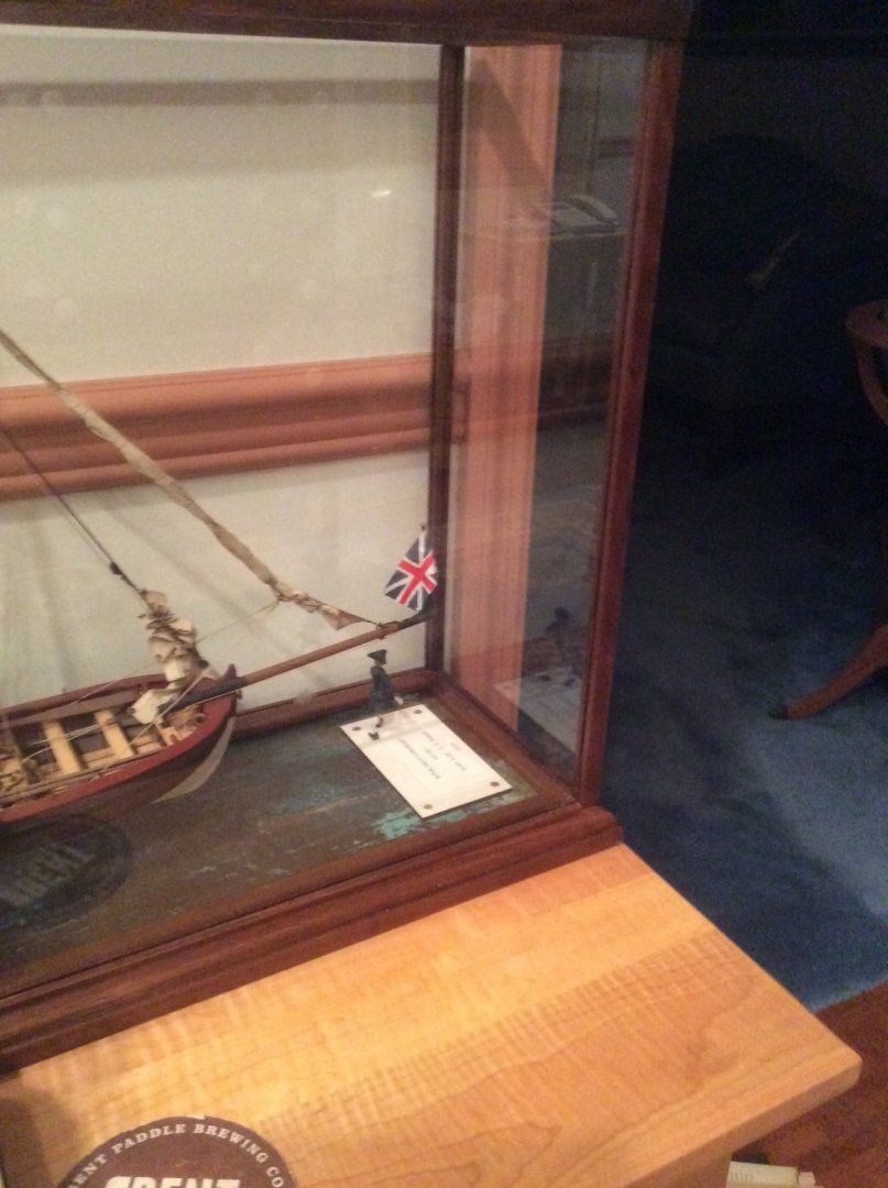
Mike,
I have a simple design for building glass display cases. The bottom is a made up of four pieces like a picture frame. Each end is mitered at a 45 degree angle It’s dimensions are calculated to fit over the base that supports the model. I have a set of 90 degree angle picture frame clamps that I use when gluing it together. Before gluing the pieces together I cut a notch in each mitered end. When glued together these notches form a square hole. The four uprights fit into these holes.
I use my table saw to groove each of the wooden members. I have a saw blade that cuts a groove slightly wider than 1/8in wide. American “ single strength” glass easily fits into these grooves. I do not need to use glue to secure the glass.
A picture might explain things better.
Roger
- Canute, GrandpaPhil, Jolley Roger and 5 others
-
8
-
Jan,
In Nineteenth Century American shipyards, they calculated a standoff or offset dimension for each frame that took into account the slope of the keel on the keel blocks. A mark was put on the top of the keel at a distance from the heel of each frame equal to the calculated dimension. When the frame was erected a plumb bob was hung from the cross spall at the top of the frame. When the plumb bob landed on the mark they knew that the frame was erected correctly.
Roger


Tool holder that makes it easy to see the tool?
in Modeling tools and Workshop Equipment
Posted
A block of wood with holes drilled in to it works fine.