


Roger Pellett
-
Posts
4,519 -
Joined
-
Last visited
Content Type
Profiles
Forums
Gallery
Events
Posts posted by Roger Pellett
-
-
I have both the conventional type, both blunt and pointed ends, and the cross locking type. Most of the time, I prefer the conventional type as the spring loaded cross locking type is more likely to launch small parts into the black hole in my workshop never to be found again. I consider cross locking tweezers and forceps to be members of the clamp family instead of tweezers.
Roger
- Canute, thibaultron and mtaylor
-
 3
3
-
Up here in Northeastern MN the native White Pine was logged off in the late 1800’s to serious environmental damage; massive wild fires causing serious loss of life, water pollution, etc. This was accomplished by lumberjacks, not machines.
Since then these lands have been taken over by Birch and Aspen (locally known as Poplar or Popple). These species grow quickly but don’t live long. Furthermore, we have lost a lot of Birch from a blight.
These lands are now being harvested using equipment like this. The wood is used for wood pulp and more recently Engineered Construction Lumber.
The more enlightened property owners are reestablishing white pine.
Roger
- thibaultron, Cathead and mtaylor
-
3
-
Naval architects consider platforms to be minor deck like structures that do not contribute to the longitudinal strength of the ship. (Modern definition)
Decks, on the other hand do contribute. In steel hulled vessels the deck plating, welded or riveted and not broken up by hatches is a major strength member. This is less true in wooden ships as the planks are not joined end to end. Here the deck clamp is the structural member that contributes to longitudinal strength, the beams to transverse strength, and the stanchions transfer loads from the beams to the keel. It is therefore possible for a ship to have what a Naval Architect would consider to be a deck that is unplanked.
-
No! I think that Jim is working on a robotic rigging machine😁.
- thibaultron, toms10 and mtaylor
-
 3
3
-
A beautiful and elegant presentation of a nicely designed boat. I have to admit, when you were posting about polishing that piece of stainless steel, I thought to myself, “It’s not going to happen,” but you did it beautifully. Well done!
A question: I missed the decision to add the propeller aperture. Why did you decide to add it when the model was almost finished?
Roger
-
Very small diameter machine screws can be purchased from wholesale houses that supply gunsmiths. There are several ways to make use of these.
First Choice: Make your own pedestals and thread the top and bottom. Drill a hole through the keel and insert the screw from inside the hull into the pedestal. Insert a second screw up from the bottom of the base to secure the pedestal.
Second choice: Drill a hole with a diameter slightly larger than that of the machine screw into the keel from outside the hull. Spray the screw with PAM. Coat the screw with epoxy and push it into the hole in the keel. When the epoxy is cured, back the screw out. The pedestal can now be mounted using the threads in the keel.
Third choice: Same as the second choice except drill the hole to the correct diameter to accept a tap corresponding to the machine screw thread. This will work with quality hard woods; Boxwood, Pear, Maple, etc. Not kit supplied MDF, basswood, etc.
Unlike wood screws, machine screws have parallel shanks, so do not put loads on the keel that cause it to s.plit.
Roger
-
It depends on how your chuck is secured to the quill.
If is is pressed onto a Morse Taper, repeated side loads can cause the chuck to come loose. Don’t ask me why I know this! If, however, your drill press quill is threaded above the Morse Taper, it is or at least was, possible to buy a collet chuck. This has a threaded collar that screws onto the quill to lock it in place. These are intended for use with router bits so would work for milling.
In the photo below, when the knurled piece above the chuck is removed, it exposes the threads that lock on the collet chuck.
Other drill presses such as those made by Delta had interchangeable quills that served this same purpose.
Roger

-
What can I say that hasn’t already been said. Beautiful!
Roger
- thibaultron, mtaylor, shipman and 2 others
-
5
-
Jim, Thanks. More to come. The inlet will be barred to prevent flotsam from being sucked into the condenser. I will of course have to relocate the outlet.
Roger
- Keith Black, Cathead, FriedClams and 1 other
-
4
-
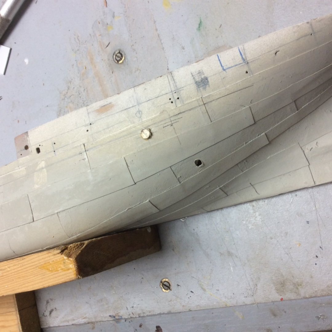
A brief progress report. Both hull halves are now plated and I am now adding details while I can still benefit from having a flat centerline surface.
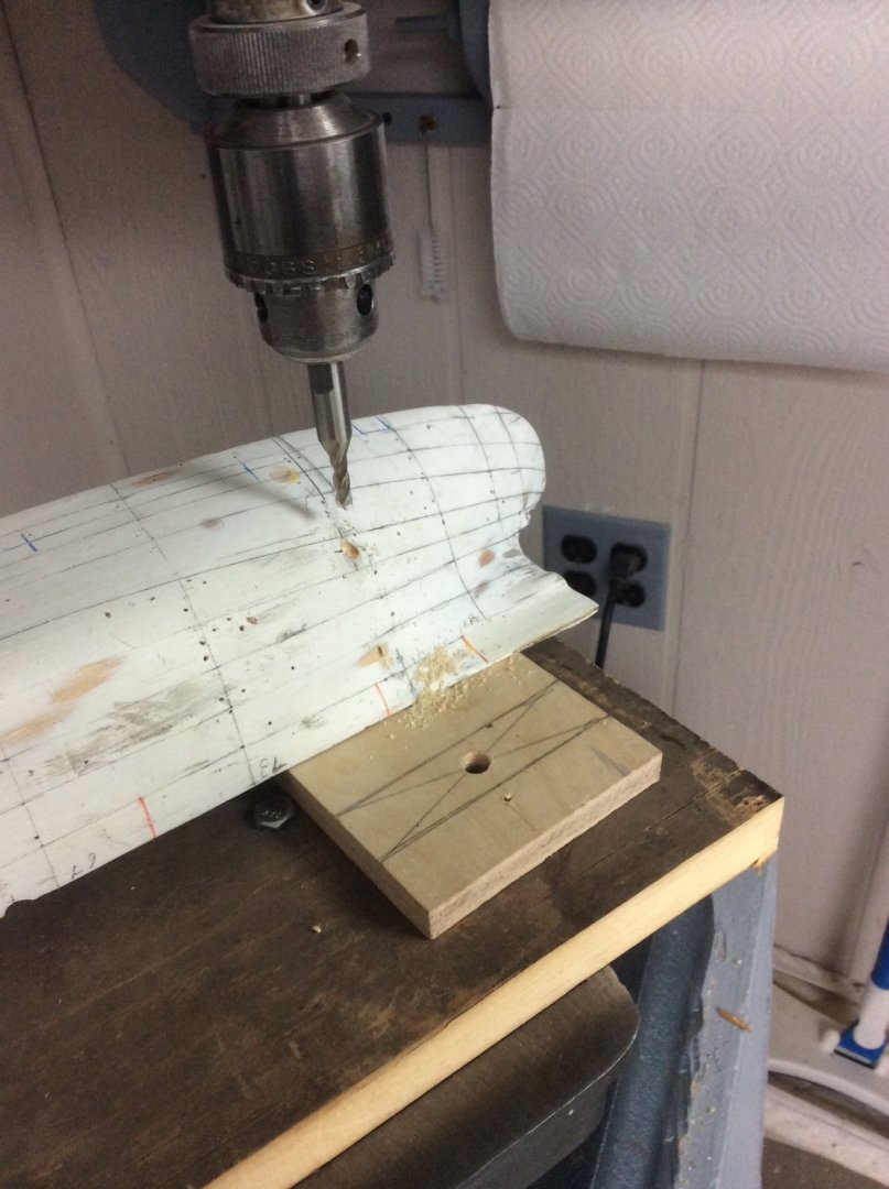
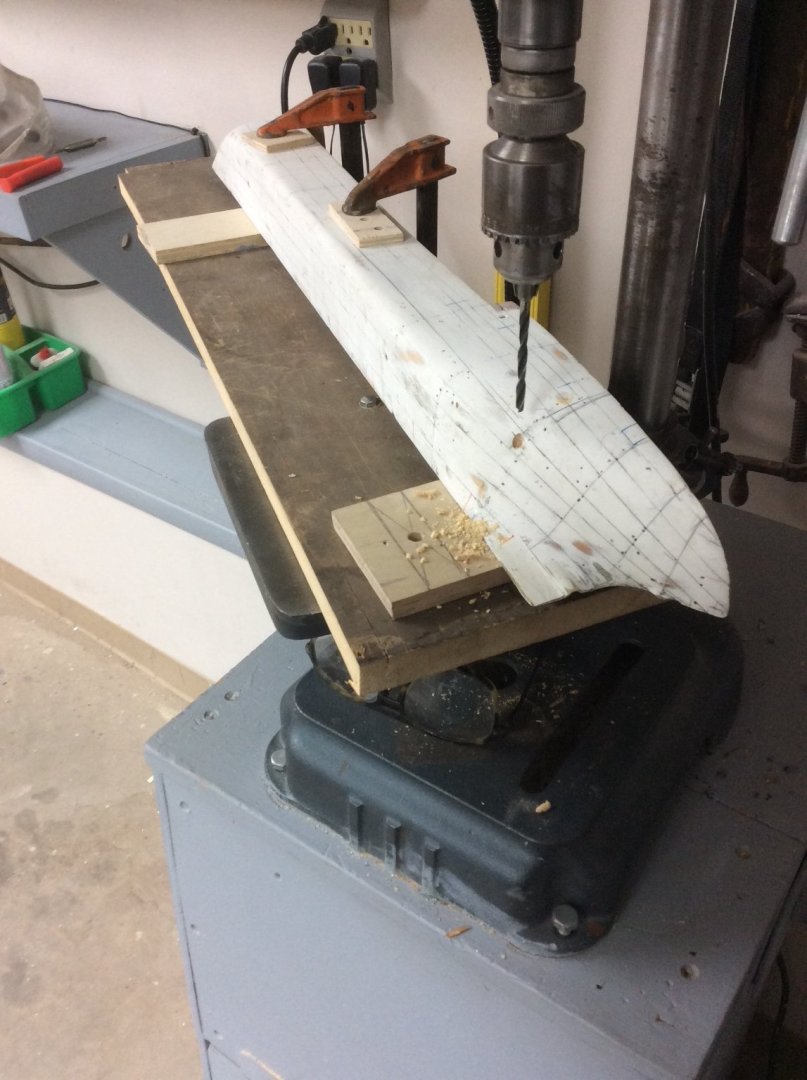
First before plating the second hull half I located and drilled the holes for the condenser inlet and outlet piping. Drilling sidehill holes is always a messy business that often
doesn’t end well. In this case, I first started the hole with a Spiral End Mill. This produced a flat shelf square to the drill press drill. The hole was finished with a brad point drill. The holes were then lined with brass tubing.The holes were not shown on the drawings so were located by photos and reconstruction of engine room equipment locations.
After plating the second hull half, I began locating the wooden fender that runs just below the sheer strake. Unlike, the piping inlet and outlet this fender is located accurately on the plating expansion drawing. Addition of the fender will be covered in my next post. Unfortunately, after plating the second hull half I discovered that the fender interferes with the condenser outlet hole. Fortunately I was able to fish the brass insert from the hole with an Easyout and to insert a specially sized plug. This will be mostly covered by the fender.
- Canute, Mirabell61, wefalck and 9 others
-
12
-
Shipman,
In the Eighteenth Century, Royal Navy, Longboats were sloop (or rather Cutter) rigged. There is ample evidence to support this- rigged models, contemporary paintings, and a detailed rigging drawing reproduced in May’s warship boats book. Unfortunately, to the best of my knowledge no one has made a detailed study of the provence of much of this information. The painting of the rigged Longboat by Dominic Serres that appears on the cover of May’s book is, however, indisputable. There is a spirited discussion elsewhere on the forum discussing this topic.
Roger
- shipman, thibaultron, Keith Black and 1 other
-
4
-
-
OC
With your painting skills I would suggest that you paint your own flag. I did this for a ship model that I built and was pleased with the results.
Use very thin paler such as rice paper. Tape it down to a smooth surface.
With a sharp pencil draw the border between the different colors.
Paint the different colors with acrylic paints.
Turn the paper over and repeat the process.
After fastening the flag to the flag pole, use a wet brush to tease it into your desired shape.
The French tricolor should be easy to paint. The gold lettering can be impressionistic.
Roger
-
Michael,
Medical conditions are not to be taken lightly and I hope that your CTS is resolved and that you can get back to doing the things that you enjoy. Visits to the neurologist are no fun; needles, wires, electric shocks, etc.
Get we.ll soon.
Roger
- mtaylor, Ryland Craze, druxey and 2 others
-
5
-
Joe, is it possible that this boat had an iron steering wheel instead of a wooden one? I’m thinking of one of the Edson type wheels used by small commercial craft.
If so, I remember a shop note published in the NRG about making one of these. From your previous posts I believe that you have a metal lathe. If so using the method from the shop note, a metal one might be easier than a wooden one.
Roger
- thibaultron and mtaylor
-
2
-
In Nineteenth Century America boiler explosions were a major cause of accidental death, and steamboats were a major contributor to this toll. Late in the century Congress finally acted to do something about the problem and delegated design of boilers to the American Society of Mechanical Engineers (ASME).
The society responded by writing a Boiler and Pressure Vessel Code, commonly known as the ASME Code. Application of the code dramatically reduced deaths from boiler explosions, although it could not stop operators from taking risks like those described.
The Code still is used today, and has been expanded to apply to piping, and even some miniature boilers used in live steam model railroads. With nuclear power on the horizon, ASME added a section on nuclear reactors and piping. Today the code has been implemented by a network of state boiler laws and in the case of nuclear power, Federal law.
The code is kept current by a system of interpretations, code cases, and revisions. While Code administration is handled by professionals, the technical content is under control of engineer volunteers from the various organizations including businesses that use it. Back in my day these volunteers met once a month in New York to conduct business. Business was by consensus. All members had to agree. Meetings were open and while visitors could not vote, they could participate in discussions and their concerns were given a full hearing. It is a remarkable example of an industry controlling itself for the benefit of everyone.
Roger
- Balclutha75, Cathead, Canute and 1 other
-
4
-
Yes, by 1900, US Navy cutters could be steered with either a yoke or a short tiller. The yoke was a fancy casting of Composition Metal, the Navy’s name for copper alloys (brass and bronze). Hitchborn includes a detailed pattern in his book. The two horns are longer than those that Druxey shows.
That being said Druxey is not modeling a 1900 US Navy Standard Cutter but a MidNineteenth Century Cutter built by a private shipyard for use by a foreign navy. The rudder pattern itself is different from that for the U.S Navy Boat.
Roger
- mtaylor, thibaultron, Keith Black and 3 others
-
6
-
Do you have a Dremel type tool? If so go to any Hardware Store or Home Improvement Store and buy some abrasive cutting discs and a mandrel. The Discs that I am suggesting are about 1” in diameter and quite thin. They are fragile and wear down quick so you’ll need more than one. They come in a little can and one can should be enough. It would help to rig up a little guide.
Roger
-
Brass or copper are the ideal materials, easy to form and solder, and strong enough. They blacken easily, with spots touched up with flat black paint. Using a harder material like piano wire would seem to be doing things the hard way.
Roger
- allanyed, Canute, thibaultron and 1 other
-
4
-
-
Adam, Et All,
I live in Duluth, Minnesota 1500 or so miles from salt water but at the western end of the five Great Lakes that drain into the Atlantic Ocean. It is the largest port on the Great Lakes with ocean access via the St Lawrence Seaway.
Duluth is best known for its cold winters. Less known is the fact that in the early 1900’s there were more millionaires per capita in Duluth, than any other city in the USA. This wealth came from the enormous mineral deposits discovered in Northern Minnesota in the 1890’s.
These mineral barons built an exclusive club to enjoy and to entertain the “Eastern Capitalists” visiting Duluth to conduct business. They named it The Kitchi Gammi Club, the native name for Lake Superior. “The Kitch” as it is known to its members is still, over 100 years later, very much a part of the community welcoming members and guests with exceptional hospitality.
For over 32 years a large picture of a beautiful young woman has hung in one of the club’s rooms. One day, I gave it a closer look and discovered it to be a painting of Emma Hamilton, Admiral Nelson’s Love, by the famous English painter George Romney. The painting is on permanent loan to the club from a local art museum and was apparently from the collection of one of Duluth’s mineral barons.
In 2019, my wife and I visited the National Portrait Gallery in London. I was surprised to find the “same” picture there. So, did Romney paint more than one picture of Emma? Is the Kitchi picture a fake? I will see if I can get the club manager interested in the picture and hopefully club members interested in The Trafalgar Project.
Roger
Ps: it is possible that we saw the picture in the Queen’s House Gallery at Greenwich instead of the National Portrait Gallery.
-
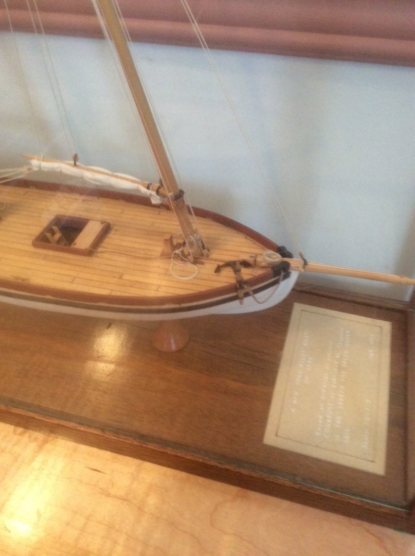
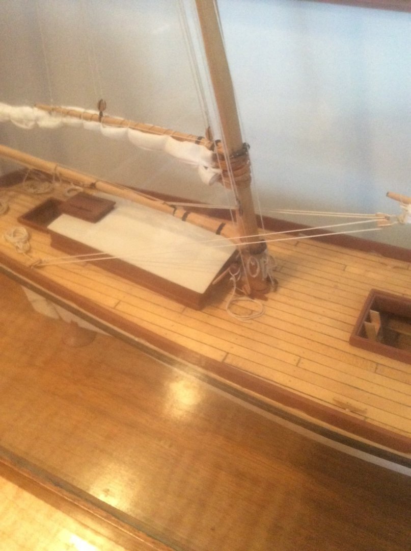
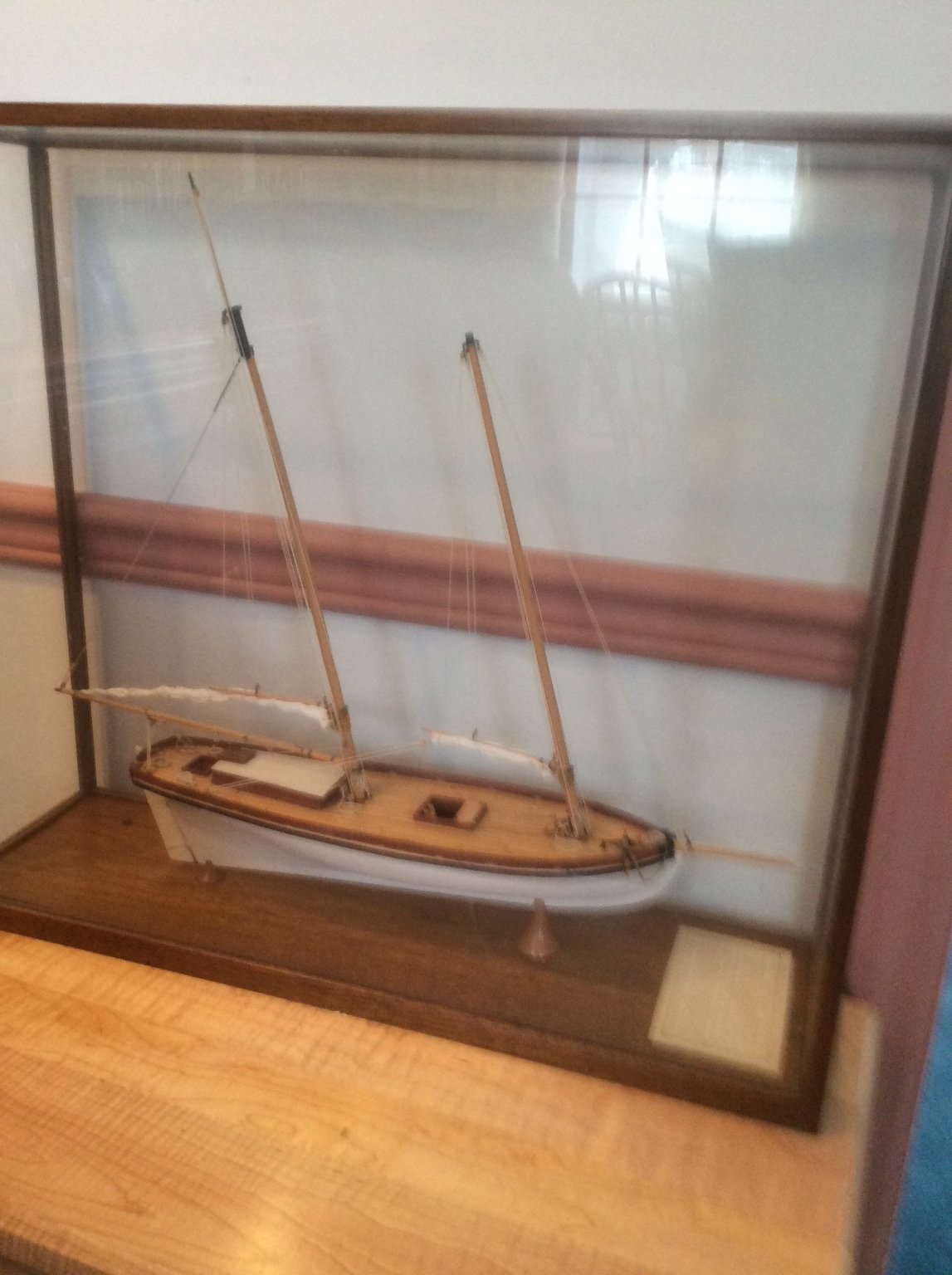
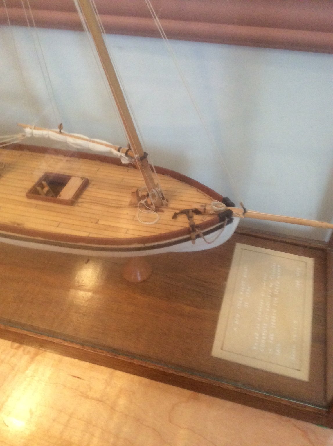
And here’s a model that I built from scratch of an American Pilot boT of the same era.

- Tim Holt, thibaultron, mtaylor and 1 other
-
4
-
From your build log, it would appear that this Swift is a kit manufacturer’s idea of what a Virginia Pilot Boat should look like, although these small sailing craft typically did not have bulwarks. They also had very little in the way of deck structures; a main hatch, a small hatch forward to ventilate the galley and a low trunk cabin aft. This cabin would be accessed by a hatch, possibly with a sliding cover. Here’s a picture of a Virginia Pilot Boat sketched by a British Naval who saw the real thing.

- mtaylor and thibaultron
-
2
-


How to make (or buy) very small rigging blocks (around 1mm)?
in Masting, rigging and sails
Posted
Last night I was browsing through my copy of Modeling Maritime History by Malcolm Darch, a highly skilled professional model maker in the U K. The last chapter in the book is about building a 1:96 scale model of the 4 masted bark Moshulu. This model required hundreds of small blocks.
Here is Darch’s System for producing them that I am NOT recommending.
He took a small diameter lead shot and cut a groove or grooves in it with a scalpel. He laid the line or lines that would be passing through it in the cut grooves and squeezed it shut with pliers. He drilled a small hole in the top and glued in a tiny eyebolt. He painted the block white.
I would seem that even professionals sometimes resort to questionable techniques.
Roger