


Roger Pellett
-
Posts
4,519 -
Joined
-
Last visited
Content Type
Profiles
Forums
Gallery
Events
Posts posted by Roger Pellett
-
-
-
-
-
My father once had a friend who lived in a suburb of Cleveland, Ohio who had made a lot of money in days gone by inventing mechanisms for controllable pitch airplane propellers. I was treated to a tour of his workshop in the basement of his beautiful home. His shop featured a heavy duty elevator with direct outside access and he commented that he was negotiating with the local power company to bring in three phase power to run a new machine tool!
For many of us, buying and setting up full sized machine tools is as realistic as my father’s friend’s three phase power. When I was shopping for a metal lathe a Taiwanese built Jet lathe, a clone of the old 4in Atlas, was about equal in price to a Sherline. The Jet weighed about 500lbs and all in all was a more capable metal lathe. Getting it home, hauling it into my shop and building or buying the necessary stand and foundation would have been a major additional cost and/or project. A full sized milling machine would be an order of magnitude more in cost and work to set up. I bought a an extended bed Sherline and later added a milling column. This has been more than adequate for my needs.
For drilling, my bench mounted drill press with its 1/2in chuck handles routine drilling jobs. For very small drills I have the sensitive drilling attachment that fits my Sherline. It works fine. I have also seen generic sensitive drilling attachments offered that would fit other small mills.
Roger
-
Beautiful work on an interesting subject.
The engineering to produce a lightweight hull capable of absorbing the power from the engine while taking the pounding from the water must have been difficult.
Is Lou, Lou Fageol?
Roger
-
Jigs and fixtures used in ship modeling are not highly stressed and not subject to much wear. They can, therefore, be made from easily machined materials that are within the capability of tabletop machine tools. I use aluminum. I have a Sherline milling column that attaches to my Sherline lathe bed and uses the Sherline lathe headstock and motor.
Roger
- mtaylor, Canute and Keithbrad80
-
 3
3
-
Wonderful work on a difficult subject!
Removable Thwarts: The US Navy typically nested their cutters and launches so thwarts were removable. At the time that this lovely boat was built the ends of thwarts in a US Navy Boats were reinforced with iron plates drilled to accept a removable iron pin to secure the thwart to the hull structure. Although this boat includes many similarities to US Navy Boats it was built for a foreign navy and probably intended to be hung from davits.
Stretchers: As a teenager, I was sent by my parents to the Culver Summer Naval School in an attempt to introduce some discipline into my disordered life. For many years Culver had used 28’ Standard 1900 US Navy Cutters to teach rowing. When I was there in the late 1950’s they still had one exhibited on dry land. These boats were much, much larger than they might appear from a model.
When I was there, rowing was taught in 26’ wooden whaleboats built in their boat shop. Boats were rowed single banked, one rower, one ore. Unlike high performance shells with sliding seats, these boats had fixed thwarts. The rowing technique involved bracing one’s feet on the stretchers and putting full upper body weight into the stroke by lifting one’s behind off the seat.
I don’t see how these large Navy Boats could be rowed without stretchers.
Roger
-
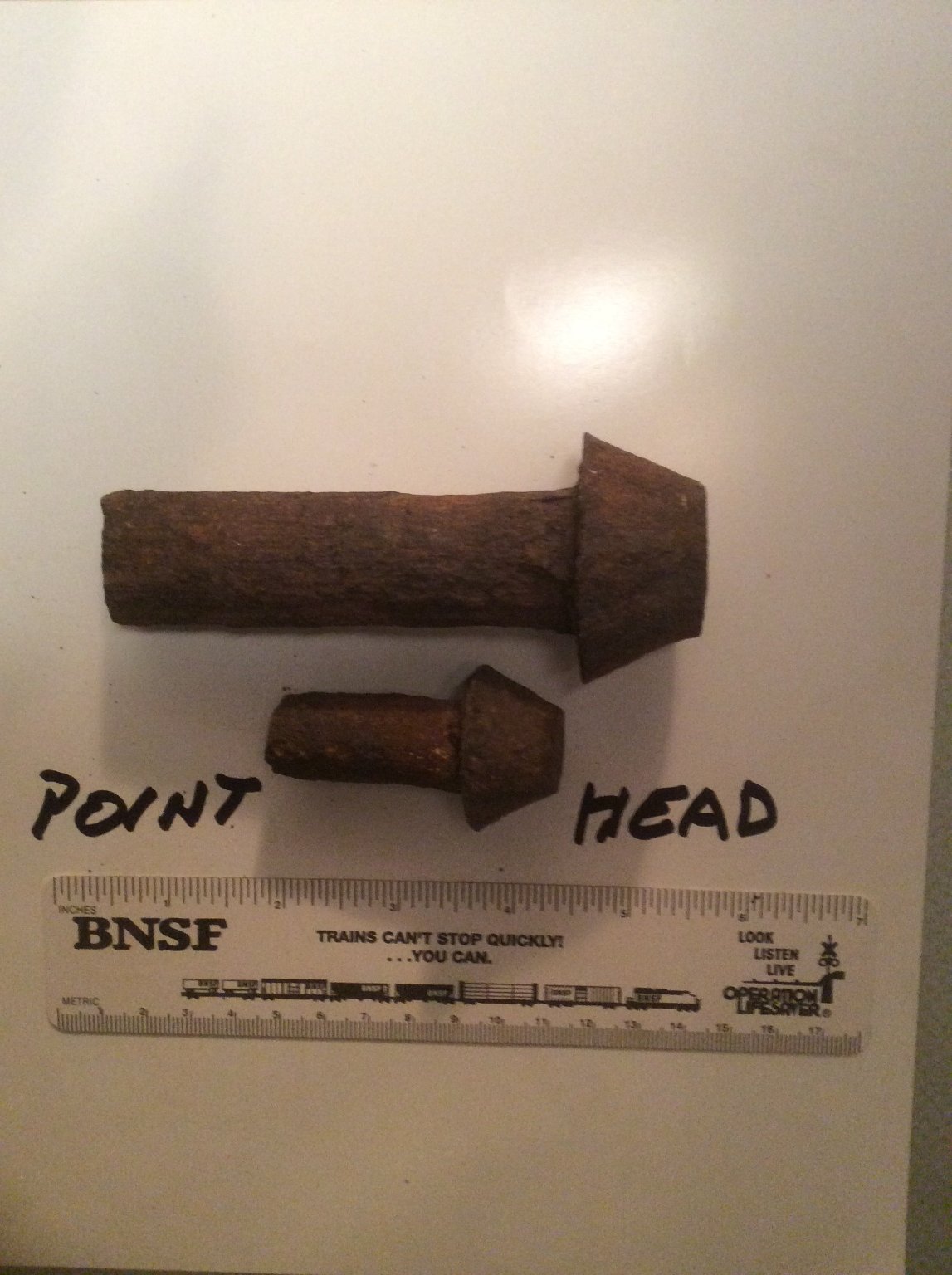
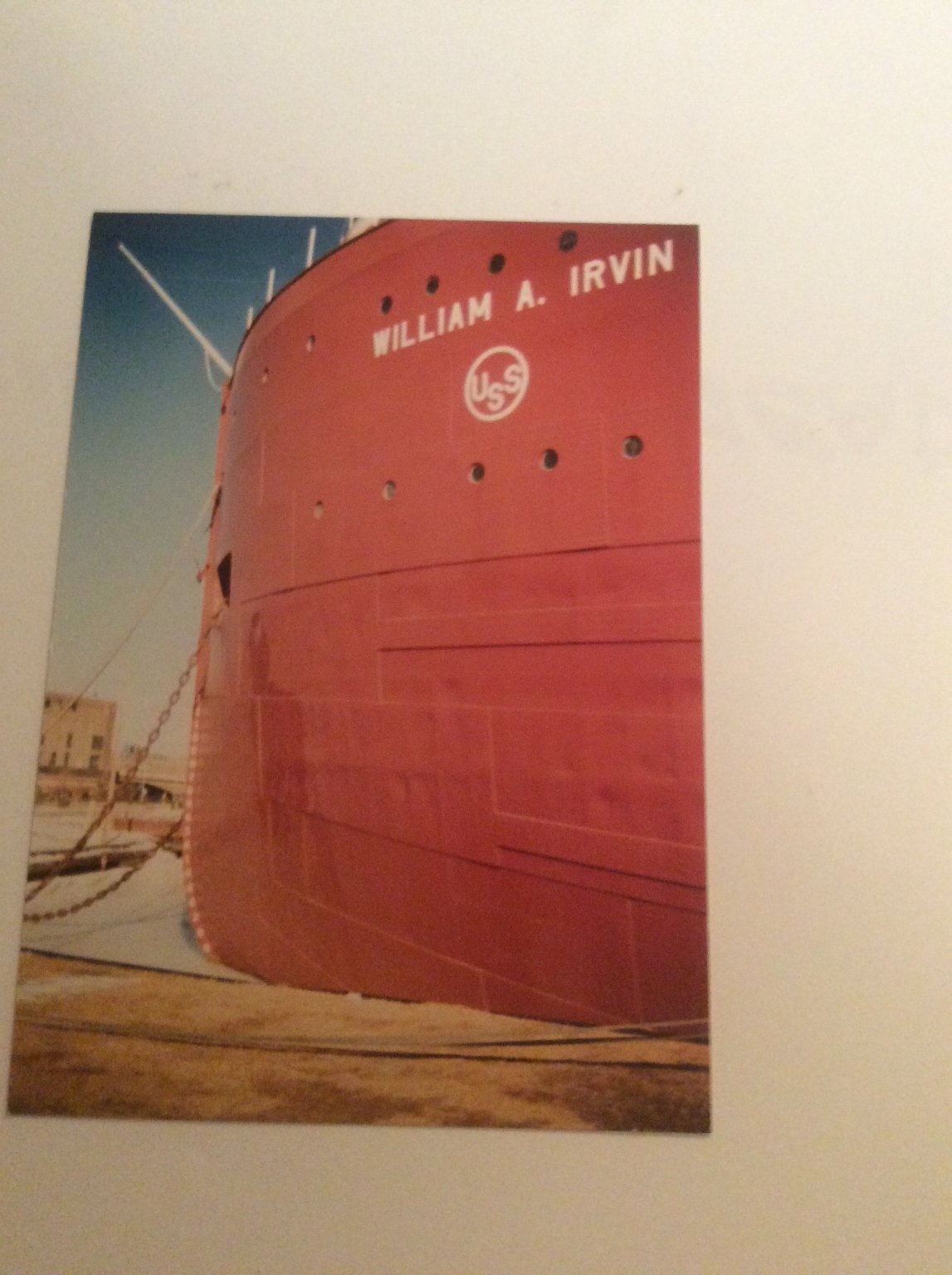
Round head rivets were not used in the hull above the waterline either. Hull structure including shell plating was fabricated with Pan Head rivets. The Pan Head was trapezoidal in cross section. The rivet was inserted from the inside of the hull so the pan head fayed against the inside hull structure and was backed up by a heavy backing tool. The plain end of the rivet called the Point was then hammered from the outside of the hull. Since the rivet was hot it was malleable and flowed into the hole which had a slight taper. When the rivet cooled it shrank pulling the joint tightly together. A properly driven rivet would have had a slight crown 1/8 in or so high on the outside of the hull. See photos. The last photo is of the William A. Irvin an all riveted ship built in the late 1930’s. Even this close up the rivets are almost invisible.
The rivet beloved by model railroad rivet counters with the prominent domed shape was called a Snap Rivet. The dome was formed by a special die. Snap rivets were used to join light gage superstructure not highly stressed hull structure.


-
Eric,
The literal answer to your question is, “I don’t know.” There is, however, some geometric logic that might provide an answer.
These ships did not have actual keels. As I explained above they were not structurally necessary, but a reinforced structure was necessary to withstand local loads when the vessel was dry docked. So, there was always a centerline out strake that rested on the keel blocks during dry docking. There was also a very slight deadrise, in Noble’s case 3in, built into the hull to concentrate local dry docking loads on this centerline strake. This centerline strake will be added to the model after the two halves have been joined.
This is means that the first strake outboard of the centerline needed to be an in strake. Riveted seams were both expensive and a source of weakness as unlike a present day welded butt joint a riveted seam is always weaker than the plates joining it (see Titanic) so there was an incentive to minimize them. On the other hand plate widths were limited by the capacity of the rolling mills that produced them. Once the plate widths had been established it was a simple matter, beginning with an in strake to alternate in and out.
Roger
- Keith Black, mtaylor, Cathead and 6 others
-
9
-
KUnfortunately, Eswee doesn’t tell us more about what he is trying to do. If he plans to SHEATH the underwater area of a wooden ship the comments above are relevant. On the other hand, if he is PLATING the hull of a steel hulled vessel it’s another matter. 1/2in plating is about right for the shell plating of smaller merchant ships.
A number of years ago, I bought a quality Guillotine type paper cutter. I use it all the time. It will cut .005in copper with minimal distortion.
I just plated the hull of my Benjamin Noble model with paper glued down with PVA Glue. (Post above in scratch built models). If I were to simulate copper sheathing on a wooden hull I would use paper too. I stabilized my paper plates with shellac before gluing.
Roger
-
The white stuff used in the 1700’s was by no means a standard color. It would have been mixed up in accordance with the ideas of the painter. Ingredients such as tallow, sulphur, and white lead would have given different shades from batch to batch ranging from a very light grey to a tint of yellow.
Start with white and add grey, yellow, tan,etc. until it looks right.
Roger
- mtaylor, Keith Black, thibaultron and 2 others
-
3
-
 2
2
-
IMHO belaying pins are one of those things where under scale looks better than over scale. Plus, much of the pin is covered up by the line that it is belaying.
They are are very easy to turn on a lathe from brass rod. Even if you don’t have a lathe a piece of brass rod can be chucked in a Dremel tool and the top rounded. Painted black, brown or grey they’ll look better than those shown above.
Roger
-
Michael,
I believe that the paper that I used was a little heavier than ordinary copy paper but I’ll measure some copy paper and let you know. I just sprayed shellac on one side of the paper and once that it dried I didn’t notice any difference between sides. The grey is just a can that I happened to have on hand. The final hull color is black with a red oxide bottom. The grey did a good job of highlighting imperfections.
Eric,
I have deliberately left off the sheer strake until I install the bulwarks after joining the two hull halves together. Whether the final strake is In or Out depends on the number of strakes around the girth of the half hull. An odd number means that the last strake will be in. Even means it will be out.
I should have noted that the paper is opaque enough to hide the marked out plating lines underneath. Therefore, as plating of the In strakes proceeds it is necessary to remark the line of the out strake onto the newly laid plate. I would therefore, think that it would be hard to work with long strips of plating and still follow the marked out plating lines.
I thank each of you for the site visits, comments and likes.
Roger
- Keith Black, mtaylor, Cathead and 4 others
-
7
-
Michael,
Welcome back! There is certainly nothing ham fisted about your results and nothing wrong with shelving a project while ponder a new approach and or regain interest. That’s what keeps things interesting. It’s not like a home remodeling project with the In-laws expected momentarily.
Roger
- Keith Black, mtaylor, vaddoc and 3 others
-
6
-
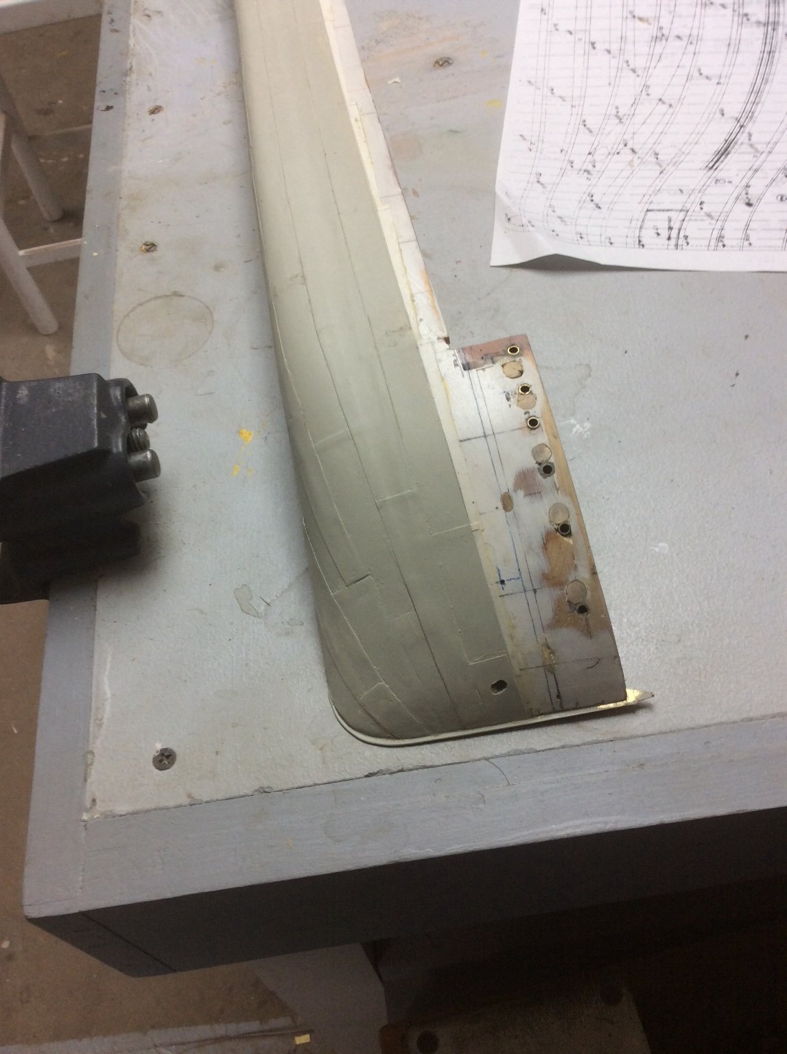
CHAPTER 6- Conclusion
From the plating expansion drawing, the plates are mostly 24ft or a scale 3in long. I estimated that 200 plates will be required. I selected a common width of 7/8in. A number of sheets of quality bond correspondence paper were sprayed with a coat of shellac and then standard 3in x 7/8 plates were cut with guillotine type paper cutter. As one end of each plate laps it’s neighbor I used a simple jig to mark a 1/8in overlap on one end.
With plates mass produced, I began plating. The In and Out system requires plating two In strakes first, and then an Out strake in between. The process for each strake begins at the stern and proceeds forward as the aft edge of the forward plate laps over the forward edge of the after plate. 90% of the time the plates proved to be a “developed shape” in other words curved in only one dimension if at all. In fact there were only 2 or 3 plates per side that had a complex shape. These were shaped by draping a wet, untreated
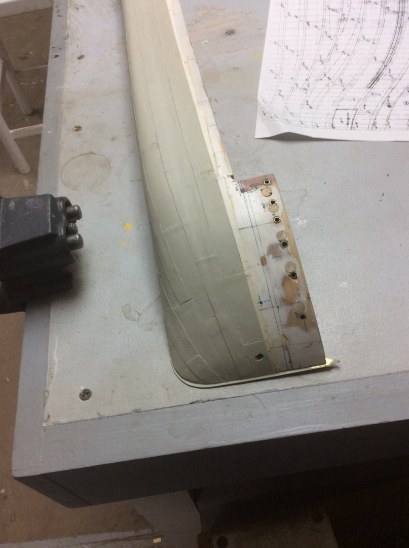
 piece of paper over the hull and letting it dry. It was then trimmed to shape.
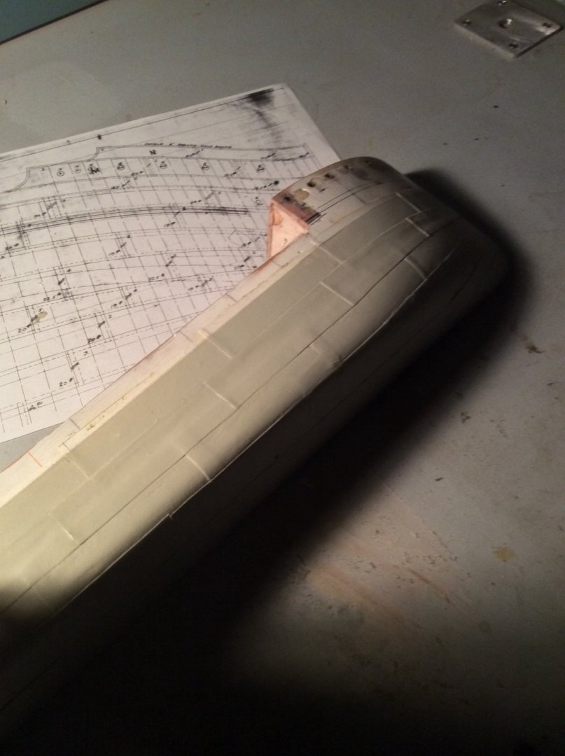
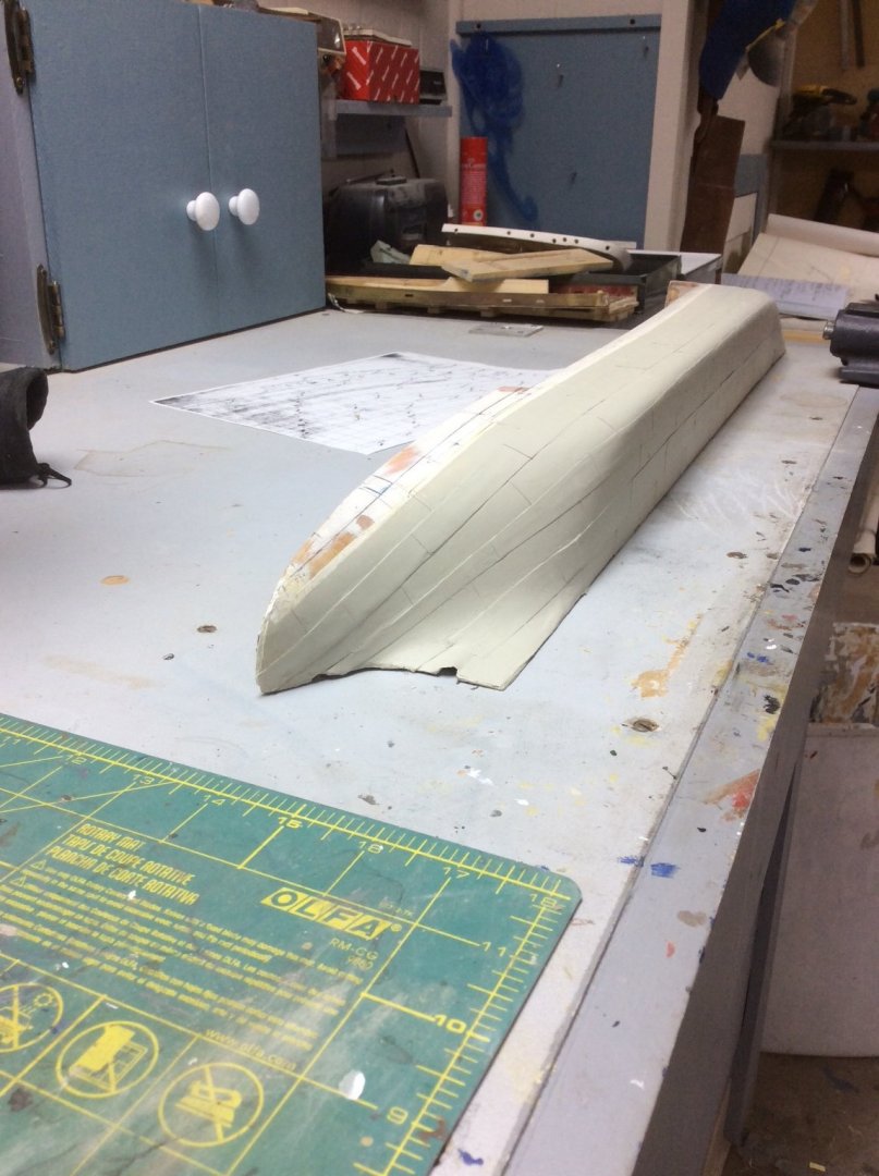
I used a palette knife to spread a layer of ordinary titebond PVA Glue to the back of each plate. When in place the plate was pressed down. After trying various clamping techniques, I eventually learned that the most effective was simply rubbing with my finger until the glue grabbed.
When finished, the hull was a mess, with glue smears, and blobs everywhere. I used alcohol to clean up the worst and then sprayed on a coat of flat model paint. The hull looked better and I found that the paint stiffened the paper to the point where it could be lightly sanded with 220 grit paper. Another light coat of paint and it looked even better. The digital photos reveal several areas that still need work but a this point, “It’s a keeper.”
Lessons Learned:
The shellac made the system possible. Several plates which for various reasons I applied without shellac were easily damaged requiring messy repair.
Keeping fingers clean to avoid spreading glue where it doesn’t belong is a problem. A bowl of warm water and a towel next to the workbench is necessary.
I made the In plates just wide enough to provide a narrow land for the out strakes to rest on. A better choice would be to make the In strakes wide enough so the out strake is completely supported.
So far, I have plated one side. In plating the second side I’ll incorporate these improvements.
Roger
-
Benjamin Noble’s construction was typical for steel hulled vessel’s built ob the Great Lakes prior to World War II; plates assembled by the In and Out method and joined by riveting. I have posted elsewhere about showing rivets on ship models. Since at a scale of 1:96, viewing the model from a distance is equivalent to looking at the actual ship from a distance of 96 feet, I have elected not to show them. I have decided to accurately show plate seams.
My original idea was to plate the model with copper or brass using transfer tape that when applied to a surface and the paper backing removed leaves a thin pressure sensitive adhesive film. When I tried this, it failed when the metal plates curled up after a short time. I put the model on the shelf while I considered other options.
Contact cement- The “good stuff” emits strong explosive fumes, and is incompatible with copper bearing materials. Like most eco friendly stuff the newer formulations that don’t give off fumes don’t seem to have much longevity.
Other adhesives- Mixing up tiny batches of epoxy to affix 200 or so plates wasn’t something that I wanted to do. CA- I am allergic to the fumes.
Paint- I have done this on another model, masking the “In” plates and painting the “out”. It worked but doesn’t show the transverse seams between plates. I filed this as a last ditch choice.
The idea that I finally chose was quality bond paper attached with the old standby yellow titebond glue, but I was concerned with the water content in the glue raising the fibers in the paper. I, therefore, tried first spraying the paper with Shellac.
The first thing that a Naval Architecture student of my generation learned is that I square foot of steel plate 1in thick weighs 40.8lbs. Since other thicknesses are proportional, shipbuilders talk, or used to talk, about 20lb plate, 15lb plate, 10lb plate, etc.
Most of the plating on the Noble’s hull was 20.4lb or 1/2 in thick. Approximately .005in to scale. The paper and it’s thin shellac coating measured .006in. Close enough!
My wife says that it’s getting late so I’ll finish this tomorrow.
Roger
-
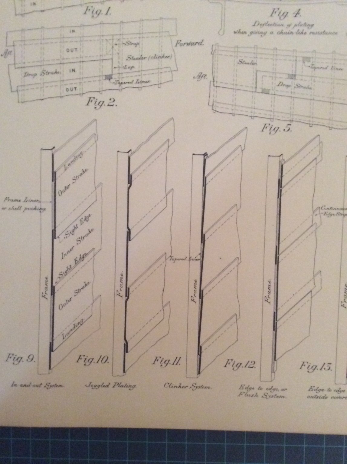
CHAPTER 6. Hull plating
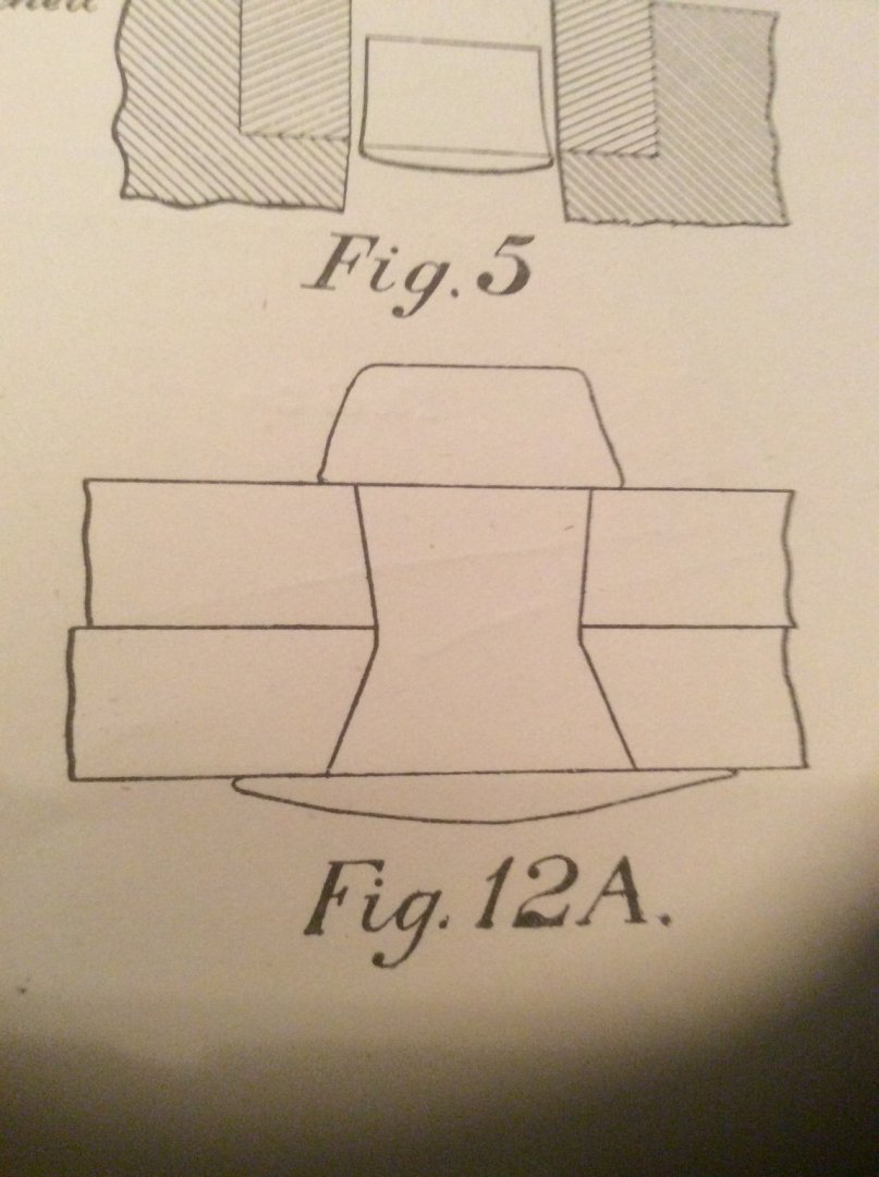
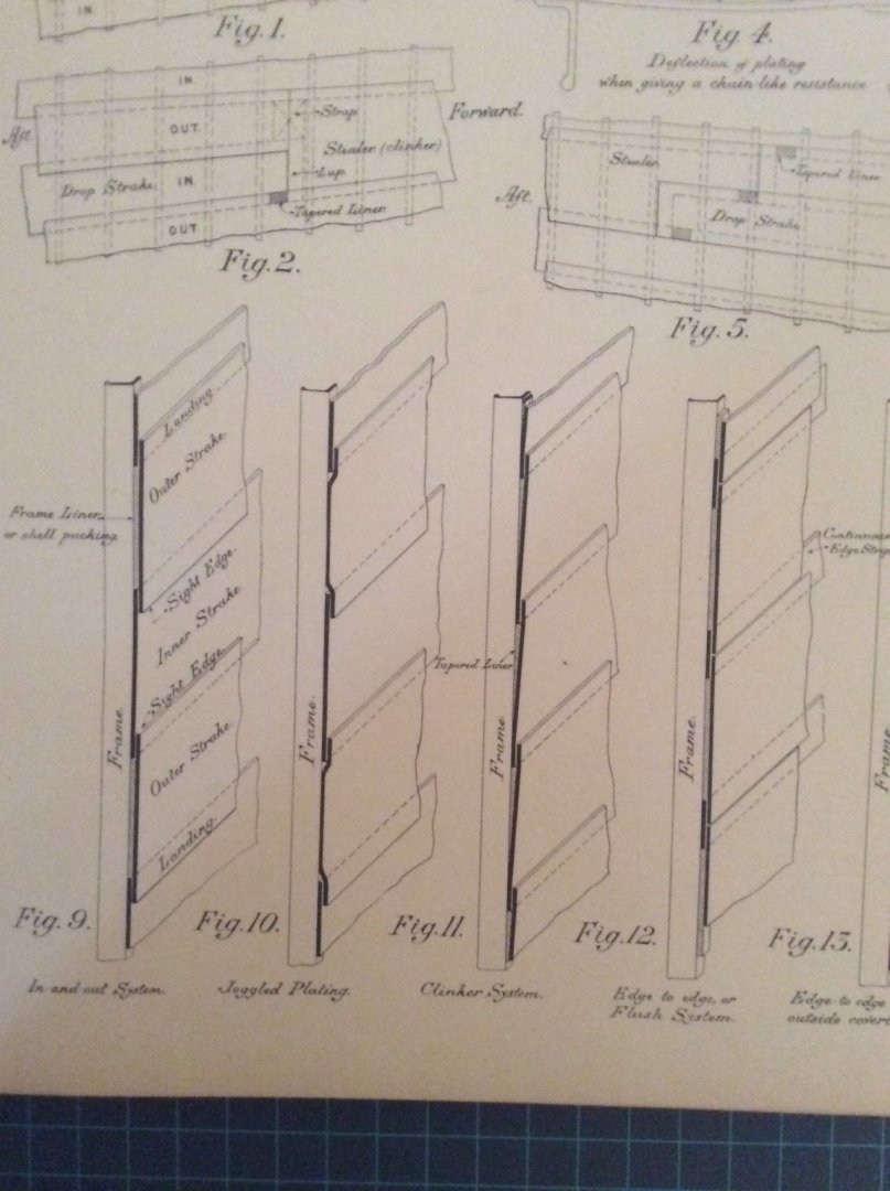
By the early 1900’s, following the lead of the great British Civil Engineers of the Mid 1800’s American Naval Architects had come to realize that the primary structural element of the hull of an iron or steel ship was its shell plating. Steel plates together with hot driven rivets provided a monocoque structure to withstand stresses from hogging and sagging of the ever longer hulls.
The wrought iron plating of the first metal hulls was layed up clinker style with the bottom edge of the plate fayed tight against the frame and the top edge overlapping its neighbor. Experience with these early iron hulls showed that the entire plate needed to be riveted to the frame so tapered liner plates were added to close the tapered gap between the plate and the frame. These tapered plates were expensive to make and nearly impossible to taper accurately leading to the In and Out system of hull plating which remained in effect as long as riveted ships were built. The In and Out Bsystem is shown along with the clinker system in a 1916 drawing from Practical Shipbuilding by A. Campbell Holms.
- GrandpaPhil, Cathead, gieb8688 and 8 others
-
11
-
Machine tools are expensive and IMHO trying to justify a purchase by determining what ship model parts you can use them for misses a good bit of the point. The question not being asked is “What jigs, fixtures, and tools can I make with machine tools that will improve the quality of my models?”
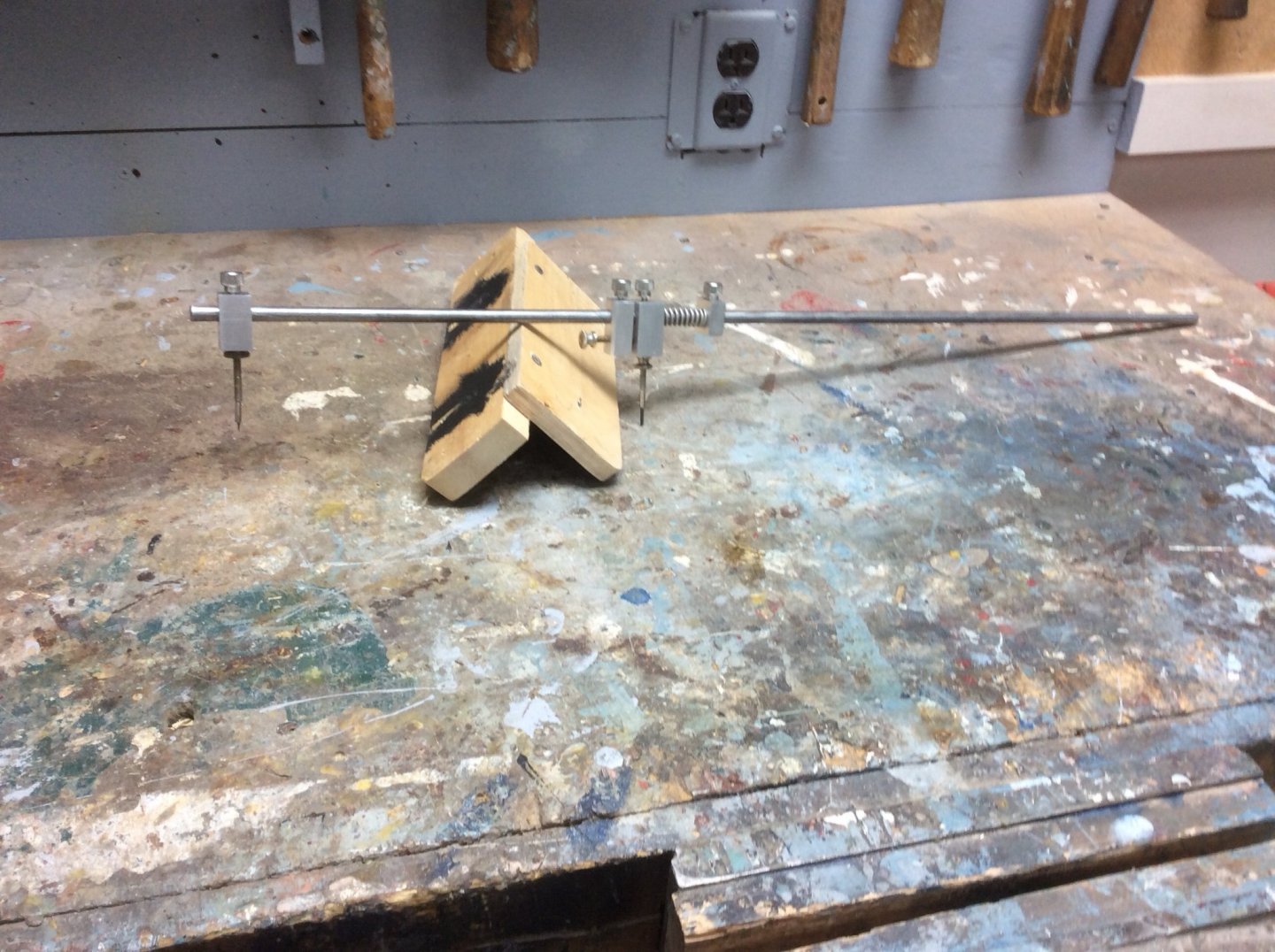
With my lathe and milling column I have made: a propeller soldering fixture, a fixture for holding small blades in my sharpening jig, a jig for soldering ladders, a height gage, a fixture for aligning a drill for hawse pipe holes, and just recently a beam compass (photo below.). My lathe headstock and tail stock are also my go to tools for accurately starting taps and dies.
Whenever I run into a ship modeling problem that requires a tricky setup I consider if I can build a jig or fixture to solve it.
Roger
-
Like most things involved with traditional seamanship, the shape of a cleat follows its function. First, the two horns allow a single figure 8 locked with a single half hitch to secure a line. The line can be secured anywhere along its length. And perhaps most important, in an emergency it is quick and easy to release the line, even when it is under tension. Since everything on the deck of a boat gets wet sooner or later, trying to untie a knot in a wet line under tension can be nearly impossible.
When handling a boat at the dock, I have seen more than one person standing on the dock holding a dock line and engaged in a tug of war with a boat under power. 100% of the time the boat will win. By slipping the line under the “upstream” horn of the cleat on the dock, it is remarkable how this little bit of friction allows the situation to be brought under control.
Threading the line first through the hole in the cleat is both unnecessary and in some cases can defeat the features of the cleat.
I second the concerns regarding CA glue. In the Shore Leave Posts you will find an account of a CA accident last January that ended with a trip to the Emergency Room. A bottle of nail polish can be bought almost anywhere for less than $1.00.
While I agree with Bob above that it is easier to not make a mess in the first place than to clean it up later, this is a goal that I have been unable to achieve.
Roger
-
Durham’s Rock Hard Water Putty or Bondo.
-
-
The Smithsonian institution has a very large model of USS Antietam, a sailing warship built in 1871. The model was built to a scale of 1-1/2in = 1’-0” as a seamanship teaching aid for US Naval Academy Midshipmen. The model was restored for the 1976 Bicentennial at which time measured drawings were prepared for blocks found on the model. The drawing was published in an old edition of the Nautical Research Journal and it is reproduced in Volume I, page 167 of the NRG’s shop notes.
Roger
-
I have no experience owning or using this tool but my professional career involved fabrication of industrial piping systems and that included bending.
When a hollow tube is bent, it becomes oval in the Bend arc. This ovality increases as the bend becomes more “difficult” Od/t/R.
OD= Outside Diameter of tube
t= Wall thickness of tube
R= bend diameter expressed as No of pipe diameters
Pipe bends made without ID mandrels or other special techniques are usually limited to 5XOD or larger radius, and American piping codes allow ovality up to 8% of OD.
So, If the flexible tube- the bending die, fits snugly over the tube to be bent ovality during bending will jam the bent tube in the bending die preventing extraction. If on the other hand there is initially a gap between the tube and the bending die the die is not preventing the tube from going oval. I don’t see how those tubes provide any advantage over bending the tube around a homemade die, a curved piece of wood or other round object.
Roger
- mtaylor, thibaultron and Jim Rogers
-
3
-
Dantist,
You’re making good progress!
I hope all of those boxes and barrels on the forecastle are temporary. Otherwise they will become missiles when she goes to sea and starts rocking and rolling.
Roger
- dantist905 and mtaylor
-
2


Treenail holes
in Building, Framing, Planking and plating a ships hull and deck
Posted · Edited by Roger Pellett
Ok, I looked things up in the book, “Ships’ Fastenings, From Sewn Boats to Steamships” and found several explanations of the practice of caulking treenails.
French, Blaise Oliver 1737:
“Once the treenail has been driven in as far as it will go, it is cut off flush with the planking at either end and a small piece of wood called a treenail wedge or spile is hammered into both ends. To realign the treenail with the sides of the hole. (sic) A thread of oakum is also inserted in a cross-shape or triangle in the head of each treenail for the same reason, and this is what is called crossing the treenails.”
English, Nautical Dictionary, Arthur Young, 1846
” Treenail plugs....a four cornered pin of hardwood with a sharp point driven into the “outer end” of the treenail to perform the the same purpose as a wedge driven from the inner end.” A Thor Borresen describing an old shipwreck explored in 1939 described this as “an old English method of caulking.”
American, William Corruthers, American Built Clipper Ship, 1997
The term “spiles” is also used to refer to the wooden “plug” covering bolt heads and deck fastenings. This is fixed over them and caulked in order to avoid water collecting where the head of a fastening is countersunk below the timbers.
As usual, is would seem to depend on who, when, and where.
Roger