HOLIDAY DONATION DRIVE - SUPPORT MSW - DO YOUR PART TO KEEP THIS GREAT FORUM GOING! (Only 44 donations so far out of 49,000 members - C'mon guys!)
×


michael mott
-
Posts
5,198 -
Joined
-
Last visited
Content Type
Profiles
Forums
Gallery
Events
Everything posted by michael mott
-
 Just finished watching your presentation Eric, thanks for doing it and for the link, I learned a whole bunch of new things about the river boats. A great presentation. Michael
- 599 replies
-
- 4
-

-
- sidewheeler
- arabia
- (and 4 more)
-
Ah yes..... more, bigger, better! The issues of being land locked and with shallow lakes around my neck of the woods. I have built and sailed 2 full sized sailboats and recently gave away the last one Maria. I have watched with great admiration the likes of Luke Powell build beautiful cutters. Perhaps in another life. I was just thinking about why I do the work that I do this morning as I woke up, and I must say that there is really only one answer and that is because it makes me happy to be mucking about with ideas about how to do this or that with a bit of wood or brass or watercolour paint. Having the time to think about these things is a luxury that I know is not accessible to many, and that bothers me. One of the joys of this forum for me is being able to watch and follow along many of the builds both simple and complex that are presented here. I read a comment about life from an author of a new book this morning "Use Less Share More" It sums up for me many of the things that I follow on this forum. Yesterday when I showed the beautiful curved lines in a bit of crab apple pruning gives me as much pleasure as spending an Hour being awe struck by the beauty and complexity of Doris's Royal Katherine made of paper and card. or GB's little fishing vessel . I learn from each. It is such a wonderful journey this learning thing. So if you had told me in 1976 that I would be using bits of this 2 foot log of maple in a model of a sailboat that I had would be working on for 8 or more years, I would have said, hmmmm...interesting, where is your crystal ball? Off now to fiddle with a few bits of maple. Michael
-
Hello Gus, I am not really in a position to advise on a kit choice because I am not a kit builder. I would agree with the comments by Keith though, one builds confidence and skill incrementally, so starting with less complex and less expensive outlay of materials will give you the ability to begin the process with less costs in time and finances. Michael
-
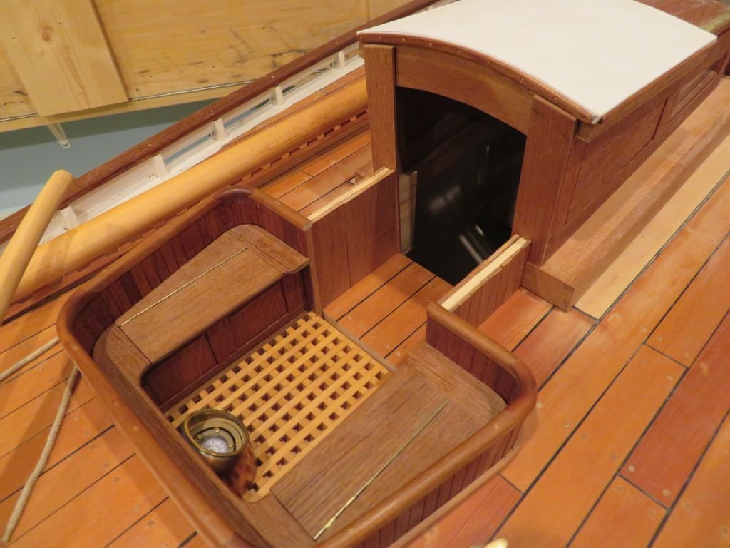
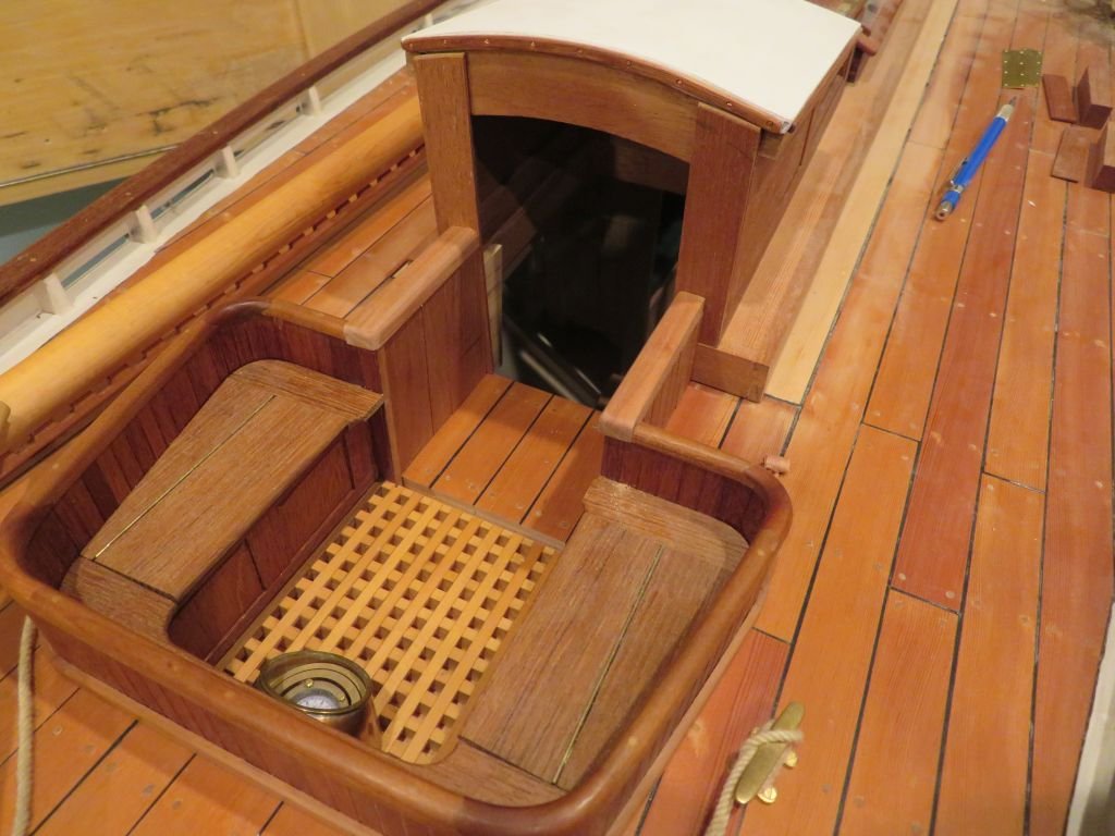
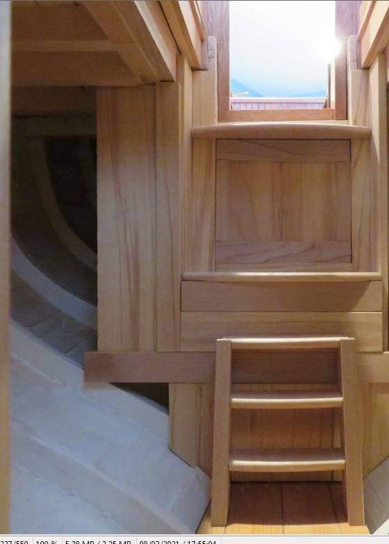
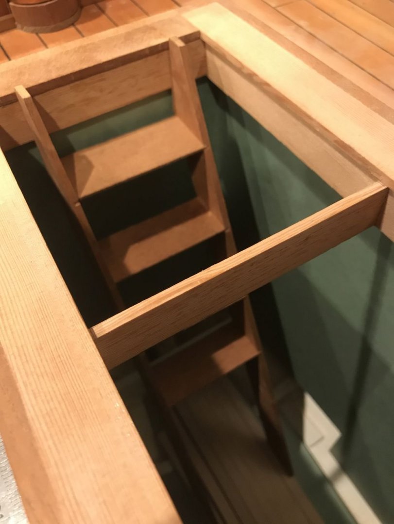
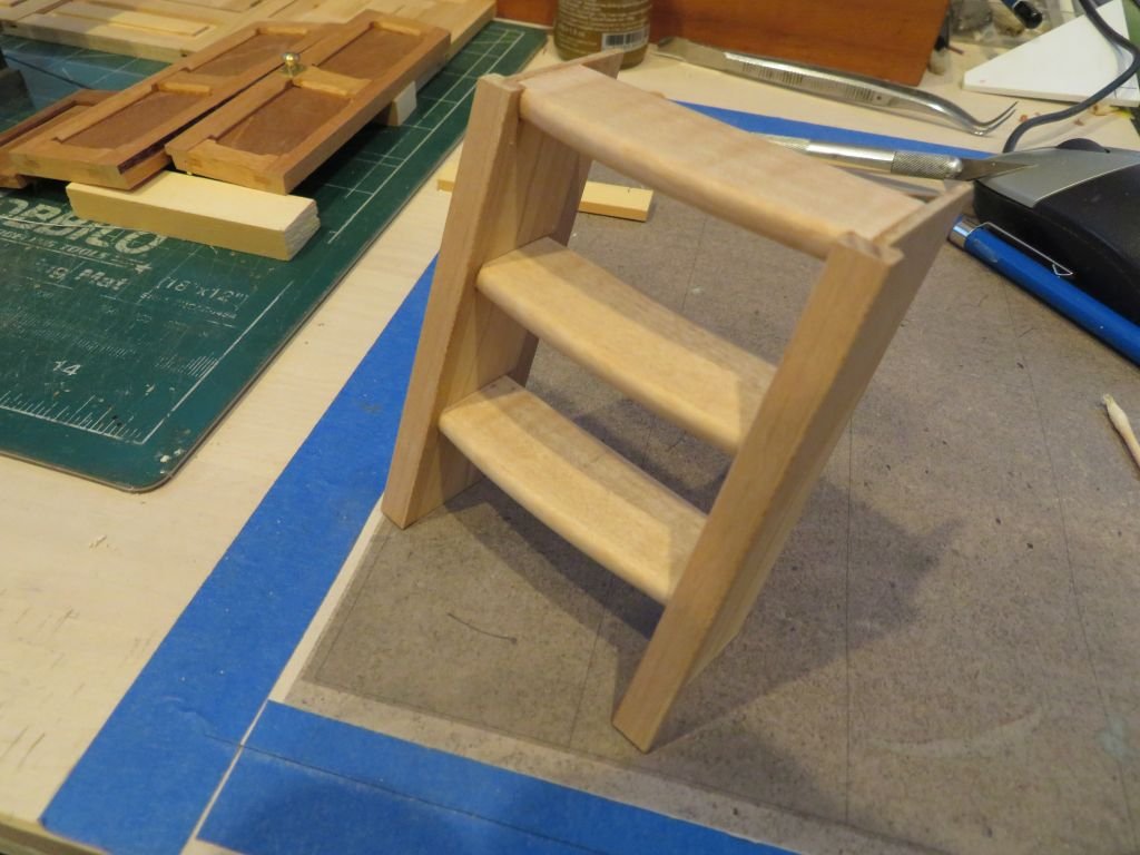
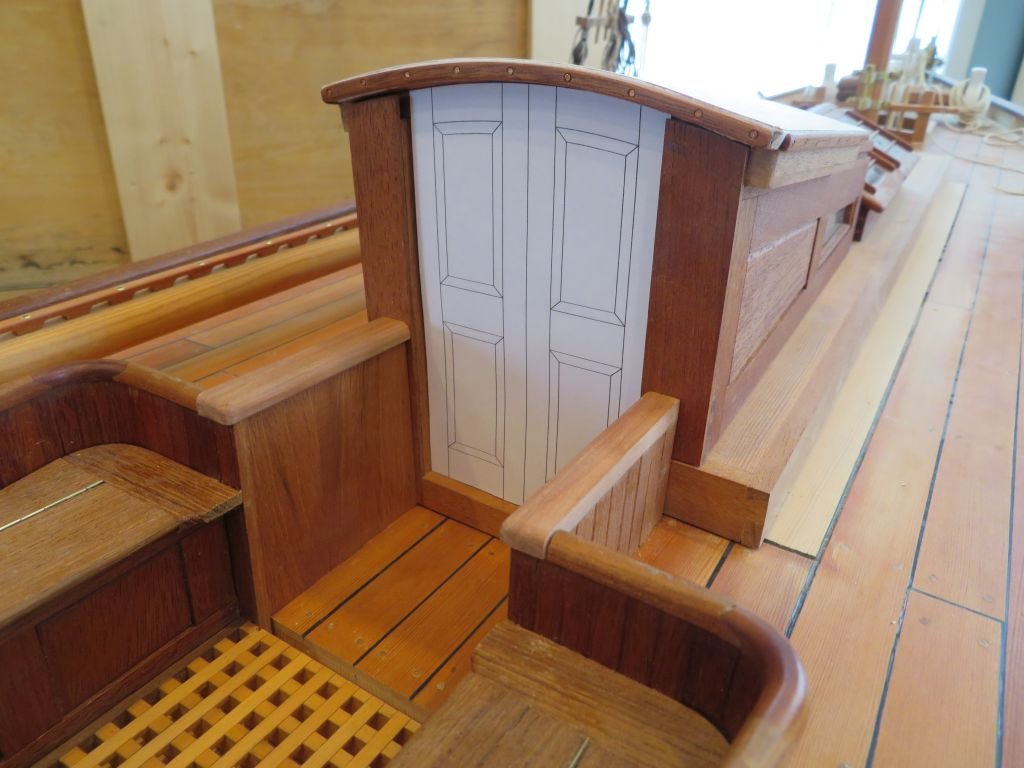
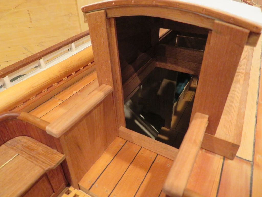
Thanks for all the likes and looks. Just a small update regarding the design of the steps The bottom set will be removable and held with a couple of simple latches, the upper set will have the middle two steps attached to the panel which is an access to the space under the cockpit and aft of the hull. Still working out the quarter berths. Michael
-
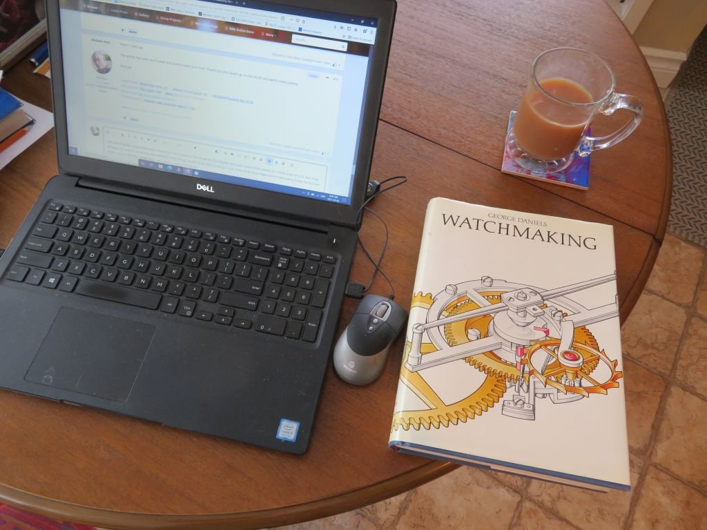
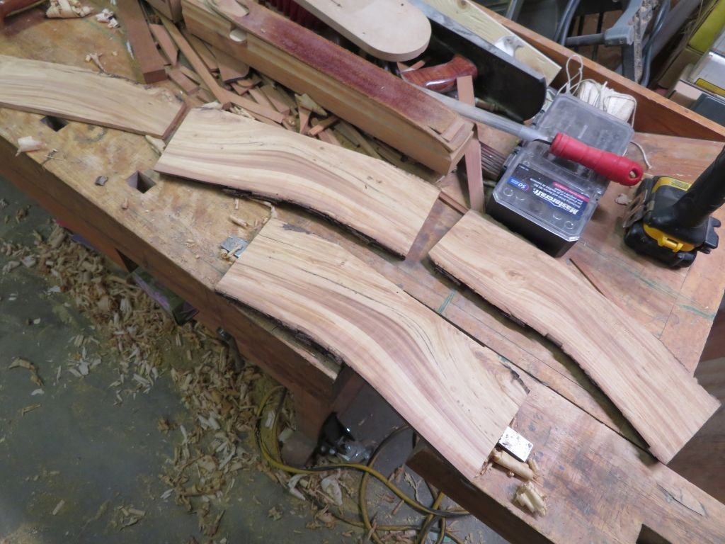
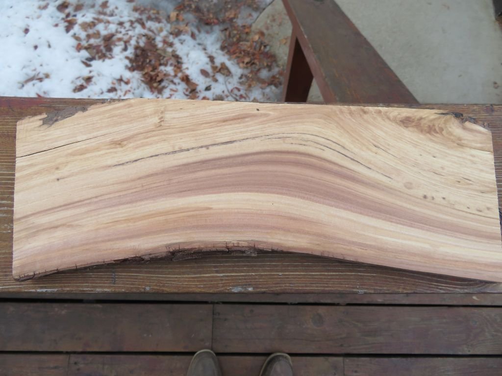
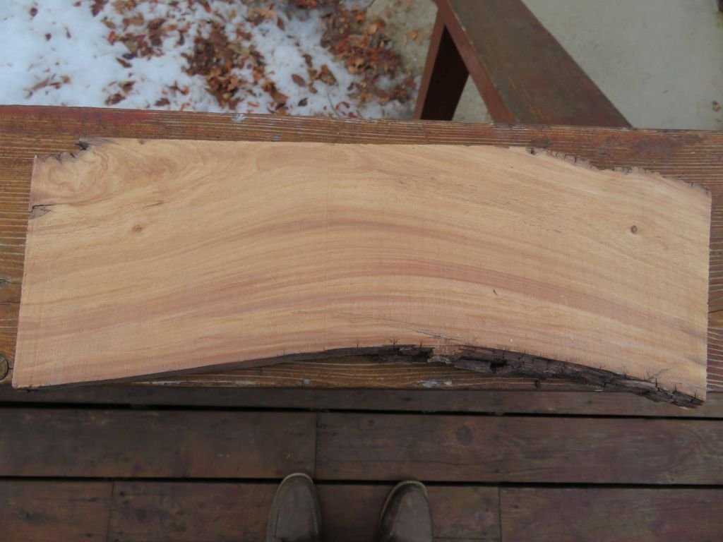
The article details some interesting methods for the creation of the model by Christopher Morrison, some of the details at 1/32nd scale of a 21 foot boat on page 222 there is a footnote that mentions that George Daniels book Watchmaking is one of the three most important modelmaking books he has ever read, I concur with that assessment, I was given a copy of this book for my 50th birthday in 1998 George makes the art of metalwork sound as easy as snapping lego bricks together. The book is a treasure trove of techniques and is full of wonderful drawings illustrating these techniques. One of the interesting things that Christopher Morrison points out in the description of Gill Smiths boats is that he used sawn natural crook frames from Oak. Planking of Cedar, deck planking of Pine ,Cedar , or Cypress. I have three types of trees in my backyard Crab-apple, Amur Maple, and Bur Oak. I keep all the pruning pieces and save some for modelwork and some for the occasional evening sit by the fire pit in the late summer evenings. here is a lovely piece of apple that I cut 1/2 inch thick and stickered after a major limb was pruned a few years ago. first the rough bandsawn side Hand planing the surface. and a close up of the smooth surface, so for a naturally curved beam. The piece is about 13 inches long. There was a replica of Pauline made called Anitra in 1988, I am hoping that there were photographs taken of the build. Michael Michael
-
The article has been purchased and downloaded and read. Thanks for the heads up. it cost $2.50 and worth every penny. Michael
-
Roger, thanks for the info I have sent Mary Van Dahm an inquiry. Craig thanks for the link and your thoughts, I have followed that thread in the past and saw the pictures before photobucket put their ugly stamp on top of the pictures. Michael
-
If anyone has a link to the article I would be most appreciative. Michael
-
An update, I heard back from the Mystic Seaport museum and they can send me 6 prints of Pauline which include all the ones that Daria Elizabeth Merwin used in her thesis. So I am looking forward to receiving them. It will be fun setting them up to do the lofting for the frames, I will use the old drafting table instead of Cad. And if anyone is in the area and willing to take any photo graphs that would be Stirling! Michael
-
Welcome from the west side of Canada, you will find lots of great help and advice from the members here. Michael
-
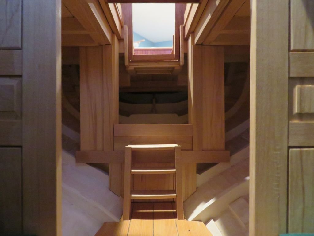
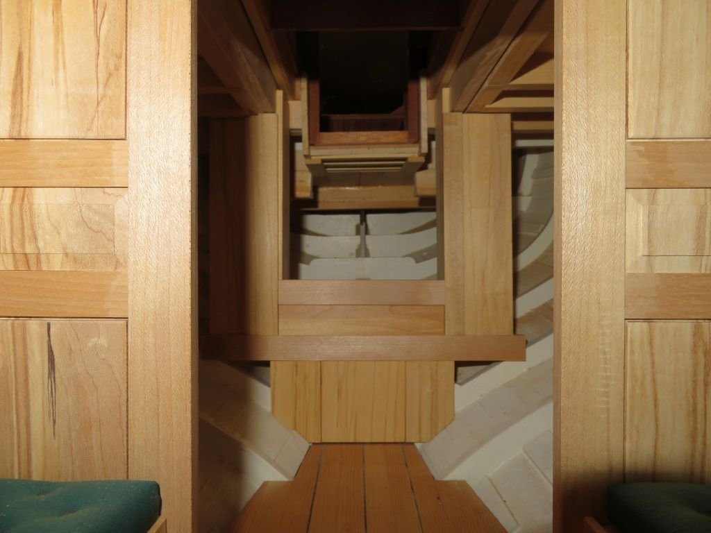
Thanks for the kind words. working on the access to the interior, the companionway steps are going to be set up differently that I had originally planned. I am now using a few scraps of some different figured maple, instead of the mahogany ones. The treads are from an off-cut of fiddle-back figured maple and the sidewalls from the old maple log. I rather like the soft curve on the steps into integrity and so have used the same motif. The rear wall of the cabin will be fixed and will act as an anchor for the components of the kitchen area and the new steps, Only the bottom 3 panels and the long cross beam are glued in at the moment, because I am still making design decisions at the moment for the upper section of the steps. The floor hooks under the wall at the stern end. This is fiddly work! I don't know how you folks who build the large 3 mast ships with all the cannon stuff and hardware do it. If I drop something it is pretty easy to fish it out. So kudos to you all who build all the deck beams and hanging knees etc, I think they would be carrying me out in a straight jacket. Michael
-
I had to look that one up Druxey, reminds me of a quote my mum used to say..."There's a difference between scratch your A#$ and tearing it!" LoL Michael
-
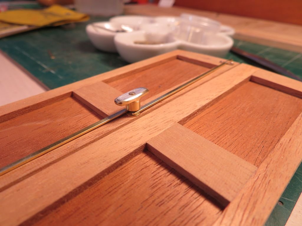
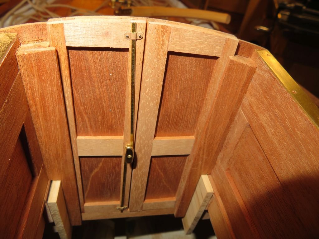
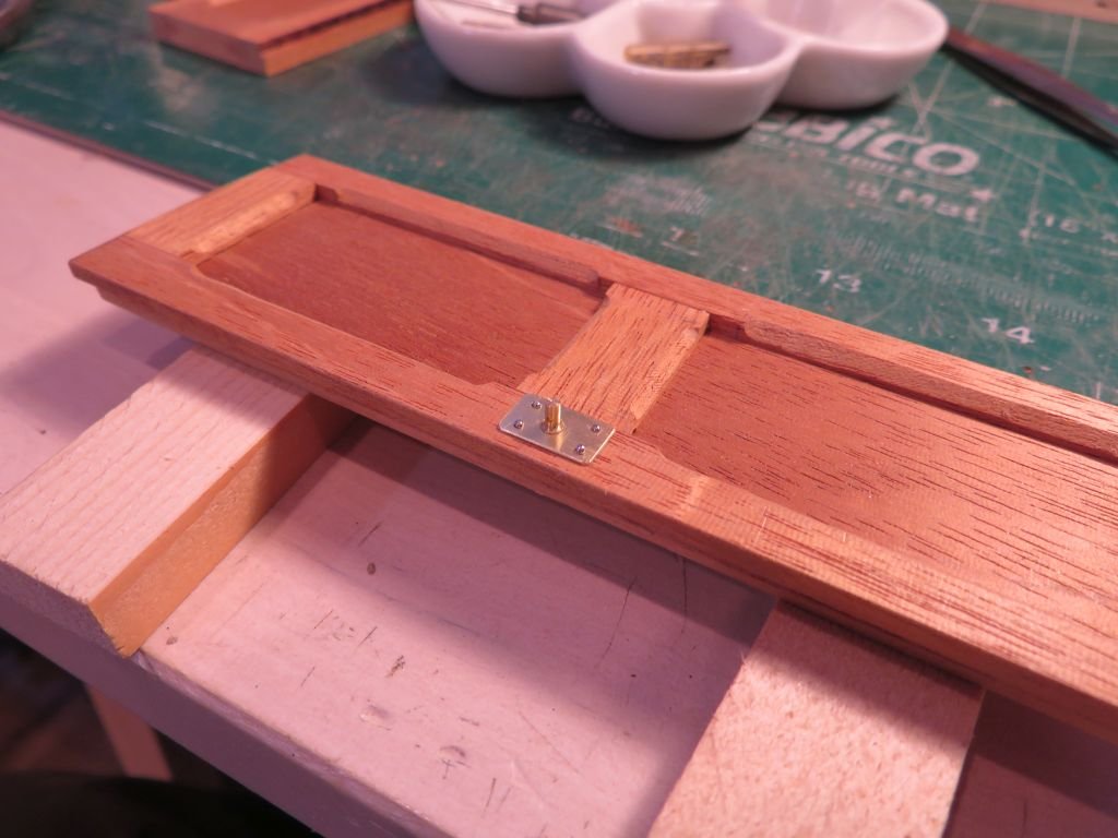
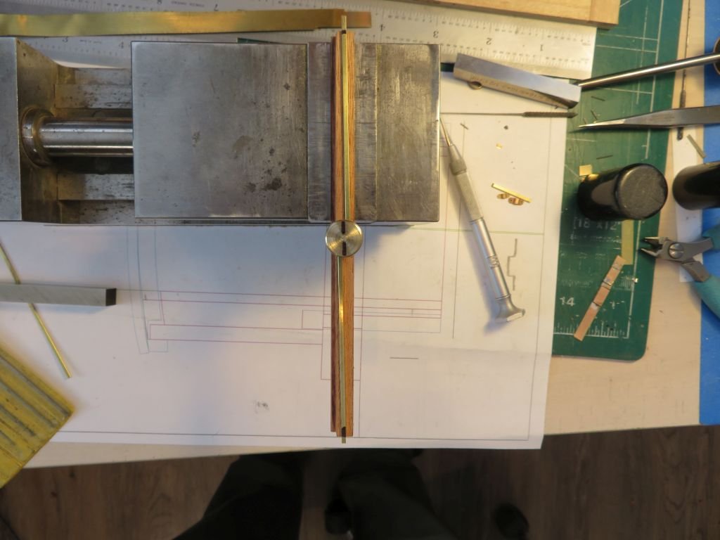
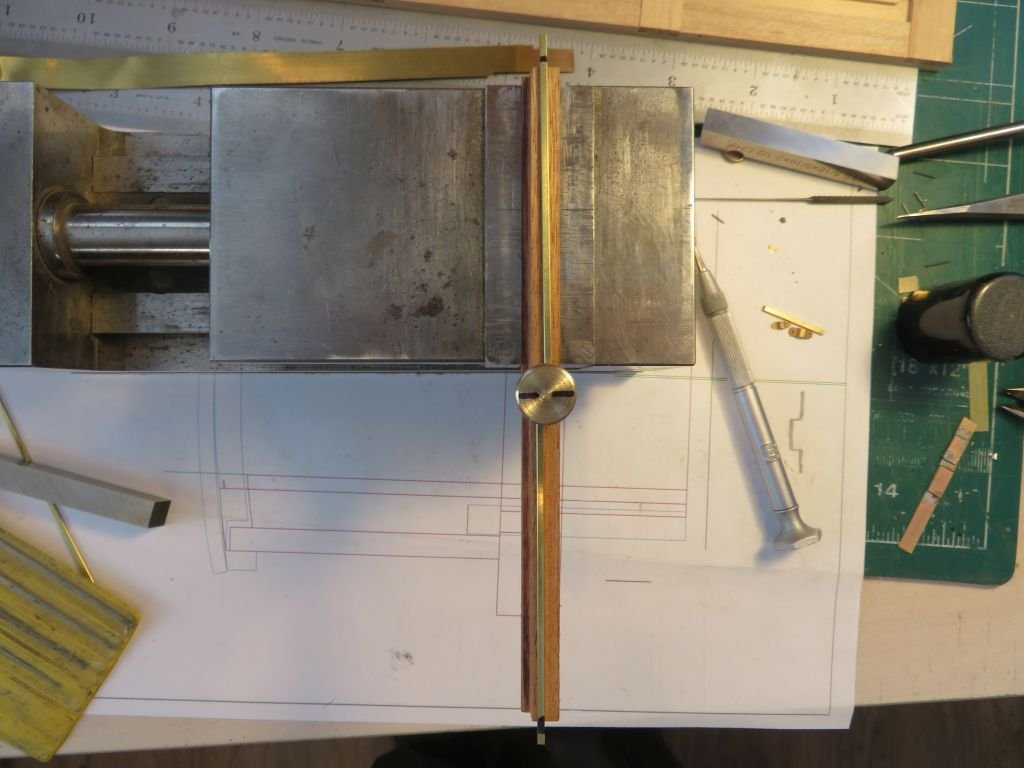
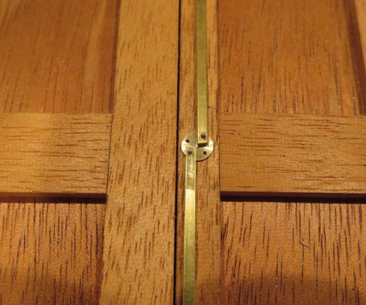
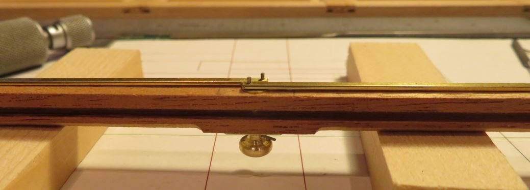
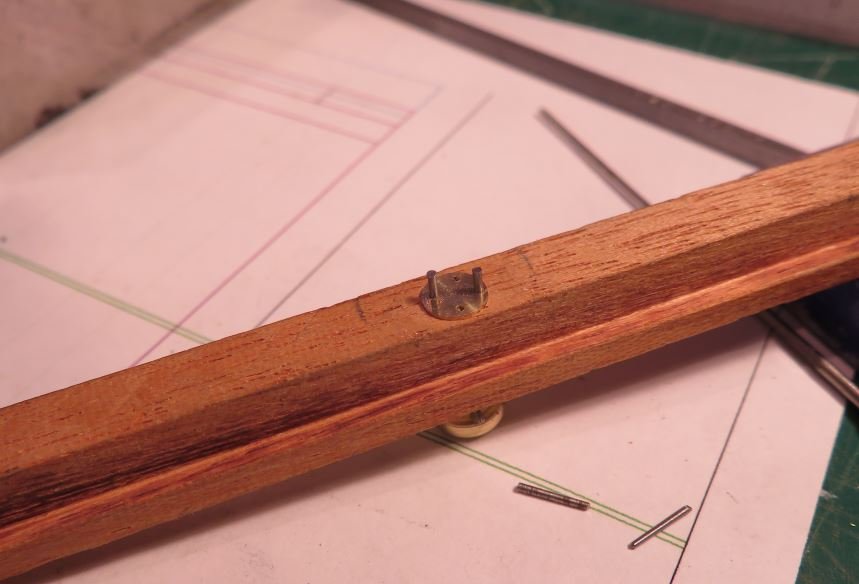
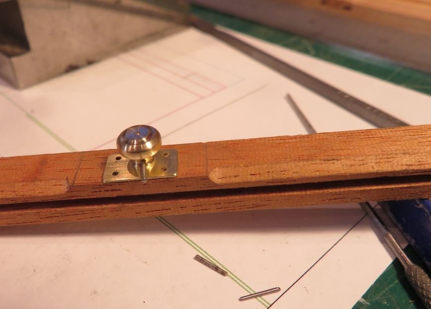
Thanks everyone for the wonderfully encouraging comments and likes. In order to capture the rods I decided that a handle could act as both the means to rotate from the inside and also act as the capture. First a disk of 1/2 inch brass was turned down to 3/16 for about 1/8 (1") and two holes .031" x .030" deep to match the pins were drilled and a clearance hole through the centre for a countersunk 00x 90 machine screw. then it was parted off the bar. This was positioned onto the rear side of the spindle and the position marked for the full extension of the rods with a sharpie. Next the surplus was removed with the jewelers saw. and was then filed and polished to the final shape. the door plate was pinned into position prior to placing the door knob. then placed into the opening to check size. The rods are cut to their final length. and the outside Now for some supper. Michael
-
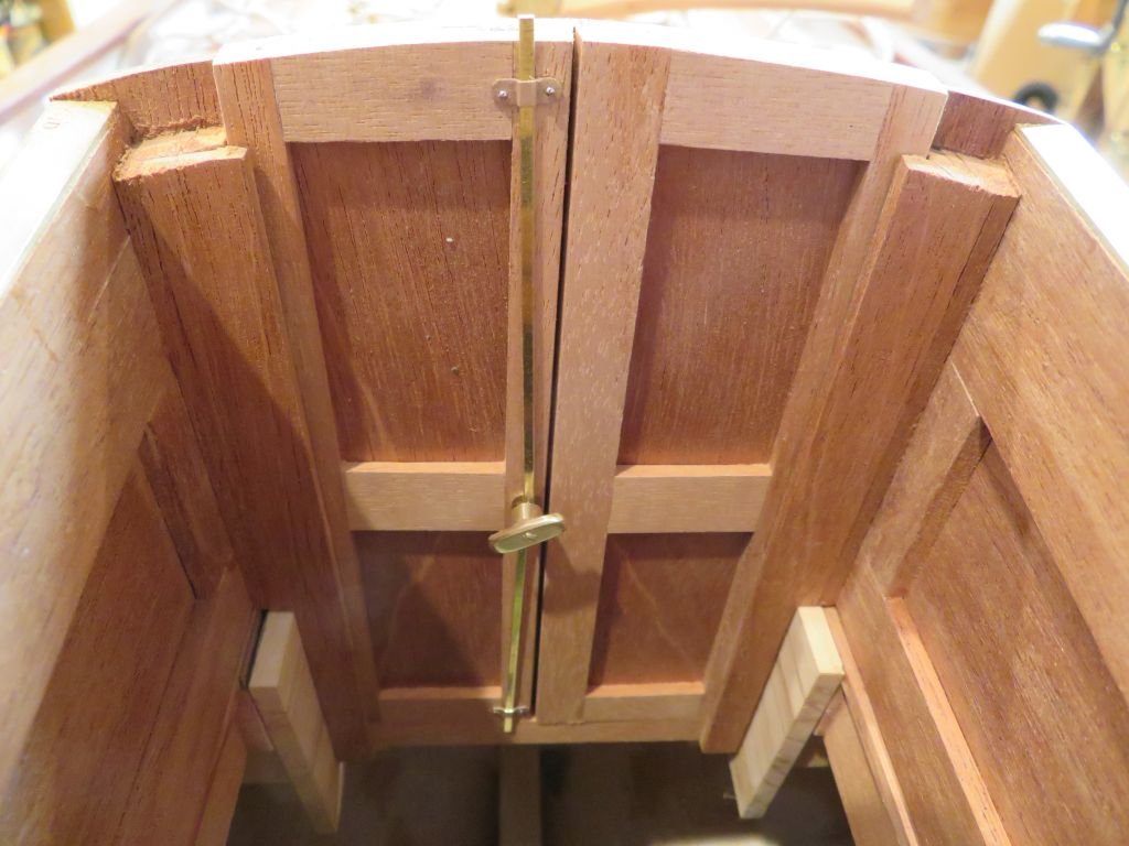
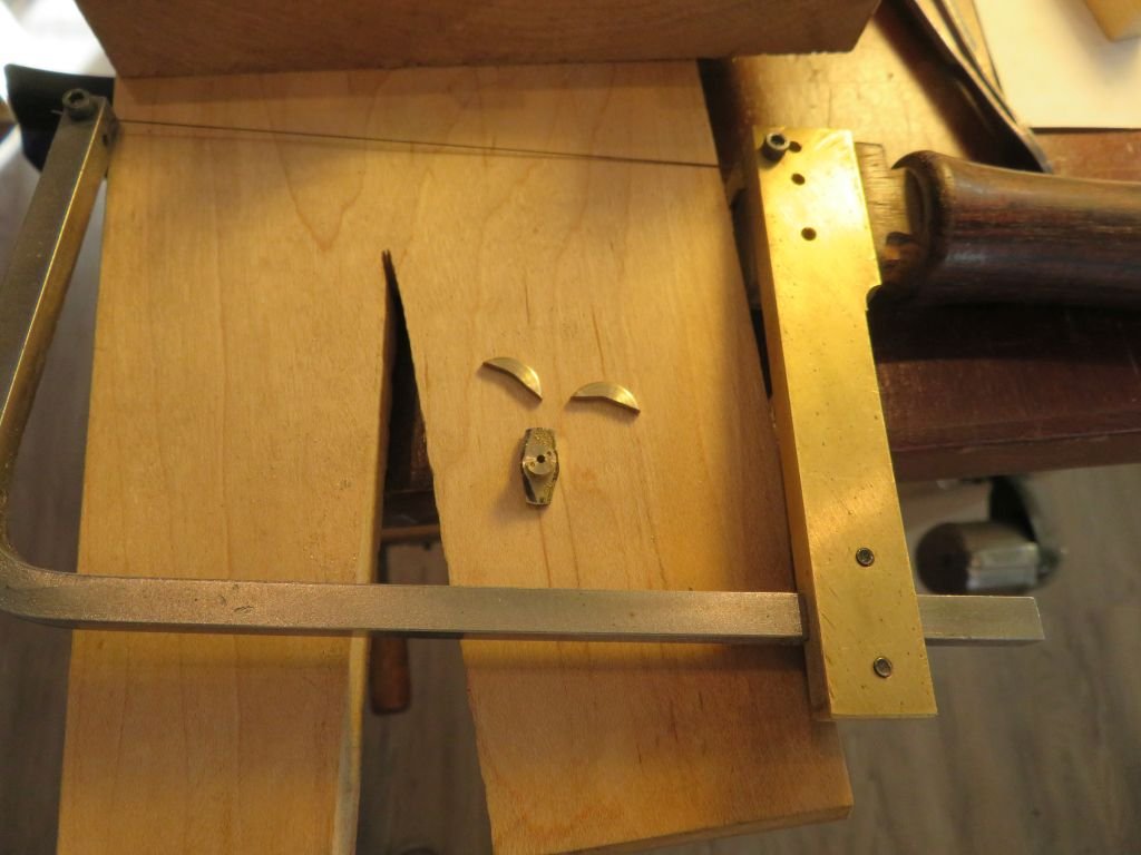
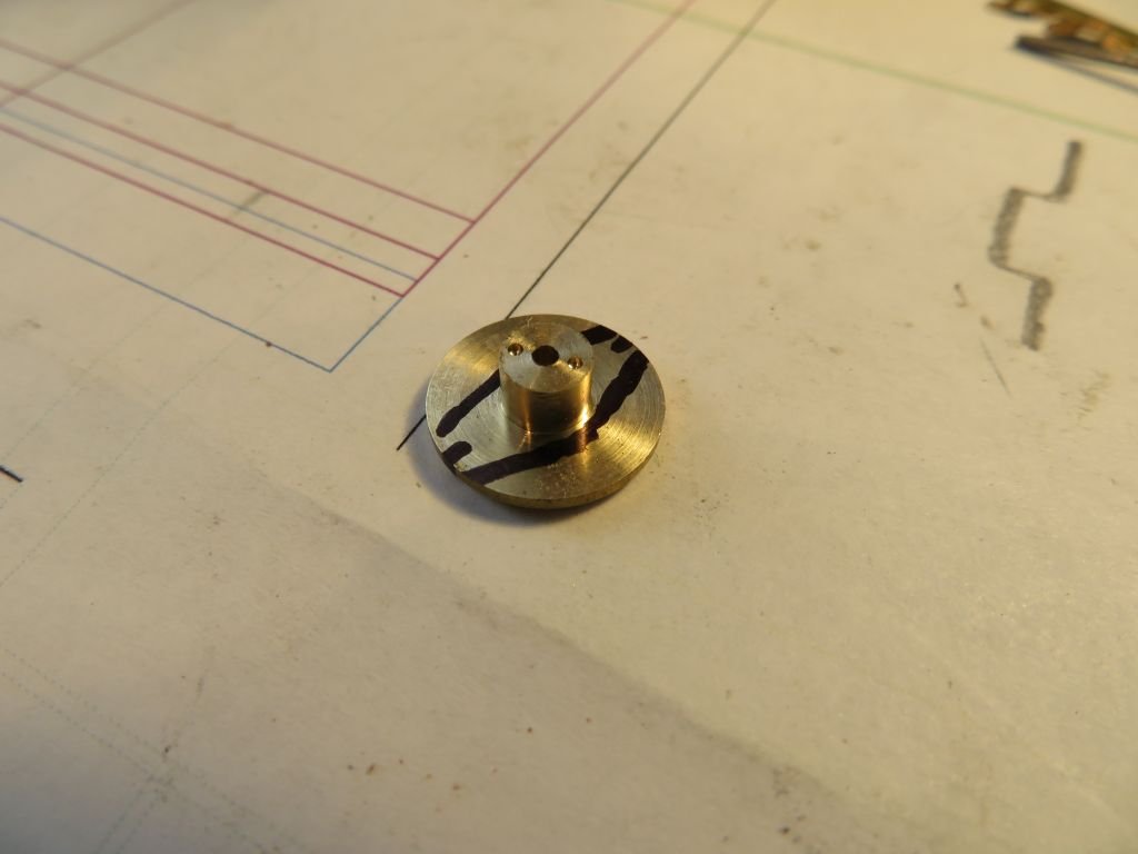
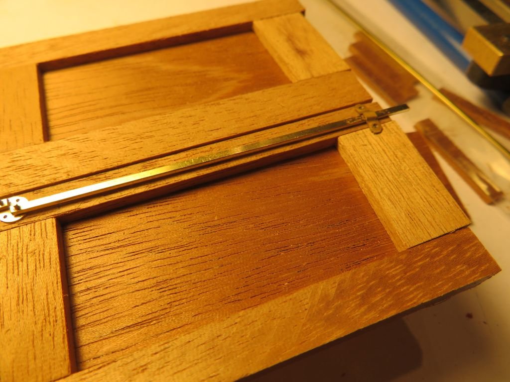
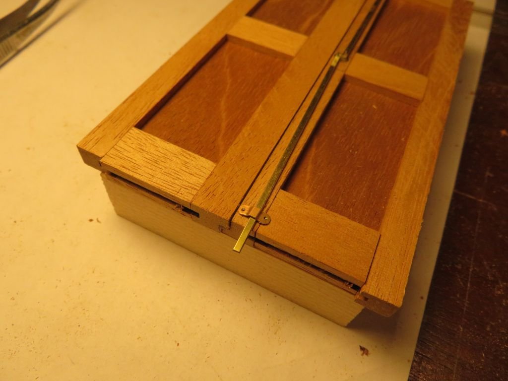
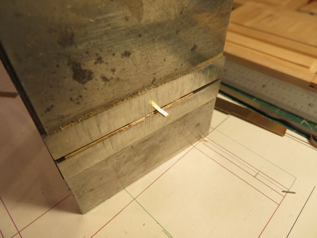
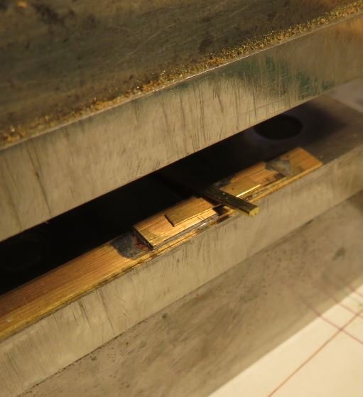
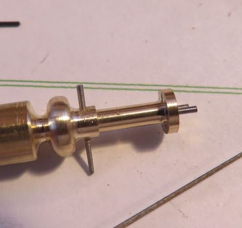
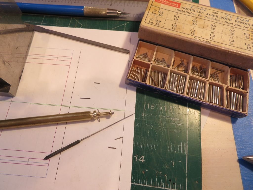
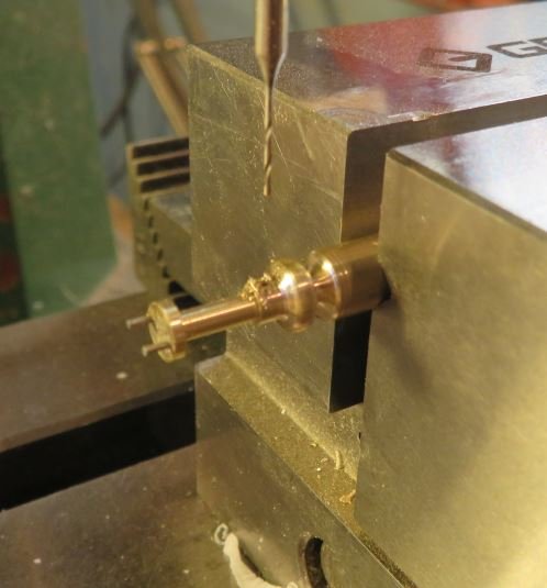
For the lock I have decided on a variation of the crash bar type rodding. First a handle spindle was turned up from some 1/4 inch brass rod and stepped down to 1/16 at the handle end then 3/32 for the section that coes through the door frame and finally 3/16 for the cam section. A separate door knob was bored out to slide over the 1/16 end. The spindle was then pushed into place and transferred to the mill for drilling the hole for the taper pin to hold the handle on. Then using the taper reamer for the third smallest pin the pin will get cut to length later. A .020 plate was cut and drilled for the door plate and the cam side was set into the door frame .030" The pins in the cam disk are taper pins that have been driven home with the tiny hammer and cleaned off. some bars of 1/32 x 1/16 were drilled out to fit over the .023" pins Next some capture plates were folded up out of some .010" using the vice as a press after punching some .020 holes and a little rough shaping it looks like it will work. I might make some cleaner ones tomorrow. and figure out the handle for the inside which will also capture the bars Ah yes then some more hinges. Michael
-
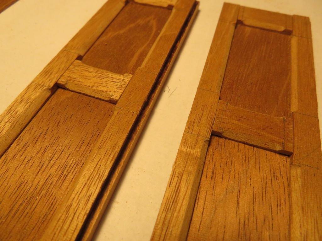
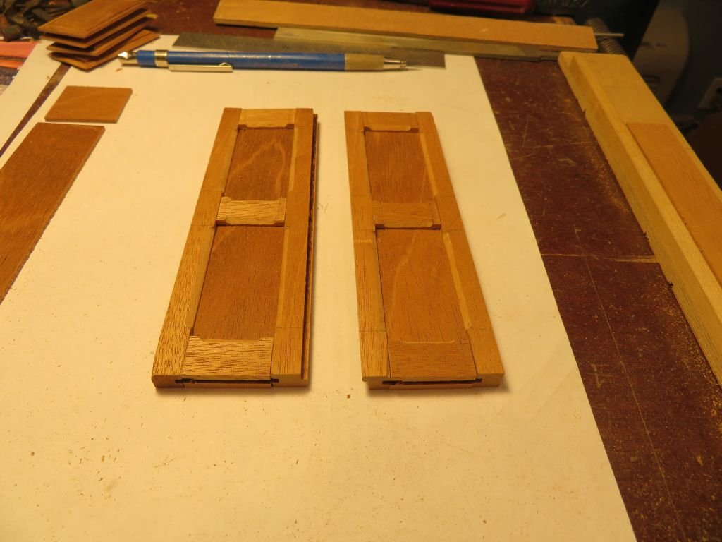
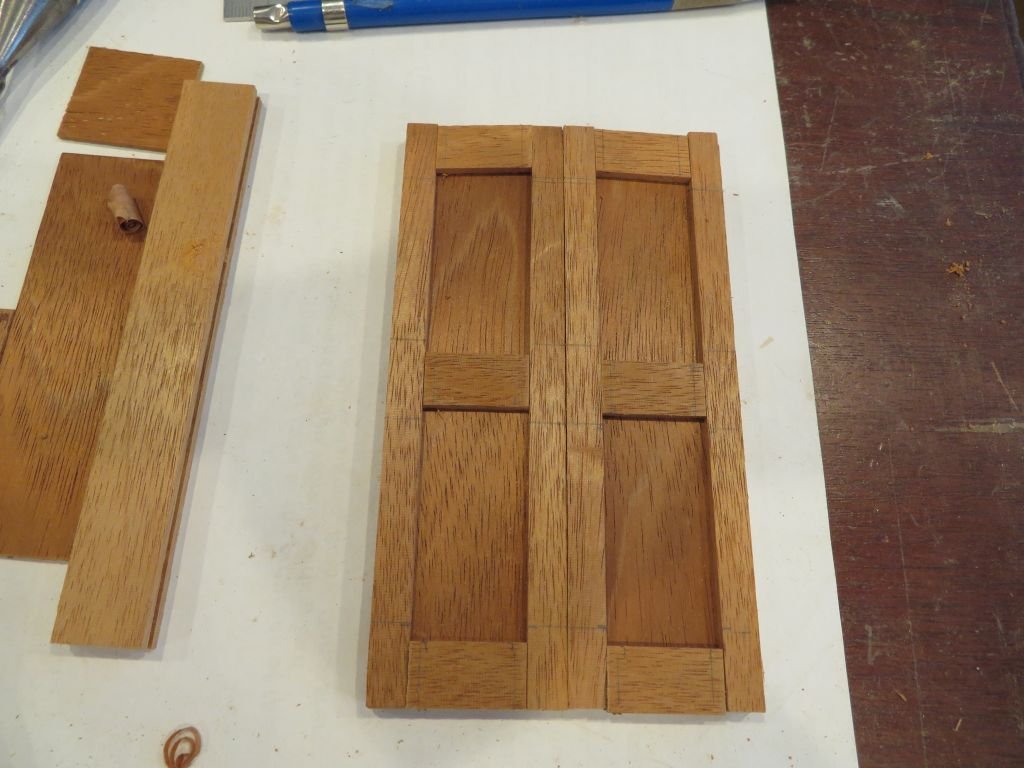
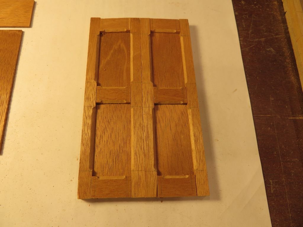
The beveled, panels looked a bit heavy so opted for a different style. I planed up some thinner panels and put a bevel into the stiles and rails. Now I need to sort out a locking mechanism. Michael
-
Hello Doris I was saddened to hear of the loss of your Husband. Your Tribute to him is beautiful. I would think that as you have mentioned how much he loved and supported your work Work is not the right word Your Art your ability to turn humble materials into magnificent models is unparalleled. That your Husband will be championing you in spirit and guiding your next model choice when the time is right. Thank you for sharing your Art and superior craftsmanship with us to enjoy. Sincerely Michael
- 1,035 replies
-
- 8
-
-

-
- royal katherine
- ship of the line
- (and 1 more)
-
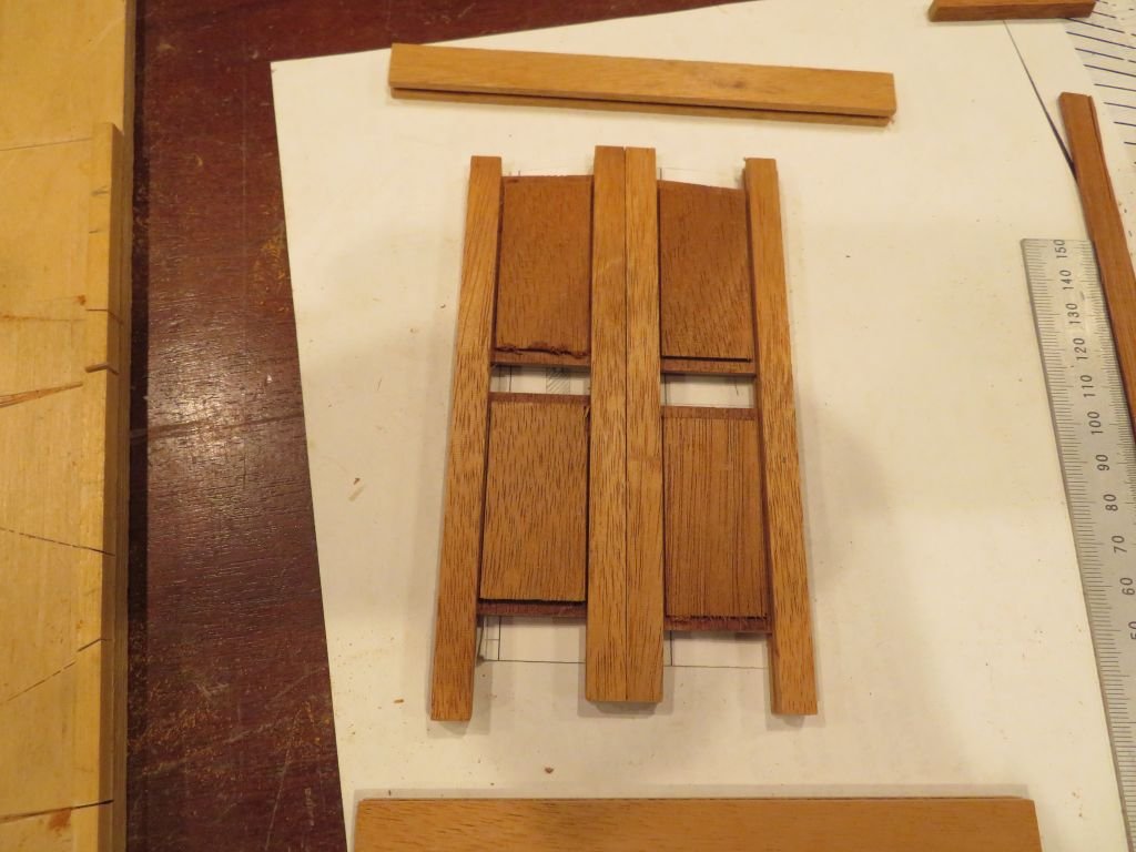
Thanks Pat, and to everyone for registering a nod with the like button. I keep thinking I should have made a lot more hinges when I was making them earlier. Also one of the troubles with Cad is that it took me ages to discover what the problem was with getting an accurate drawing of the doors to the companionway. Cad is much too accurate! I was taking measurements and putting them into the drawing, and then the next measurements were conflicting, and things seemed to be mismatching. I even set up a sting datum line from stem to stern to double check the details of the cockpit and companionway, Printed out the doors cut them out and they did not fit cleanly. Went back did more and different measurements, printed it out again, another different slight mismatch. Then I discovered that the deck is 3/64ths lower on the port side than the starboard and that there is a 1/32nd parallelogram to the companionway relative to the deck. A final adjustment to the drawing "as built" Ah then it fit. Then I was able to prepare the wood for the doors. The rough elements still a lot to do shaping the panels, but at least some progress after a frustrating morning drawing. Michael
-
Hi Mark Just catching up Glad to see that you are back working on the ship. I had missed your earlier troubles so am happy to hear that your health issue is receding into the past. And that you are moving forward with the planking. As has already been stated our focus on our model work is a great healing power. Michael
-
and welcome for the other side of the country as well, nice looking pup. Michael
-
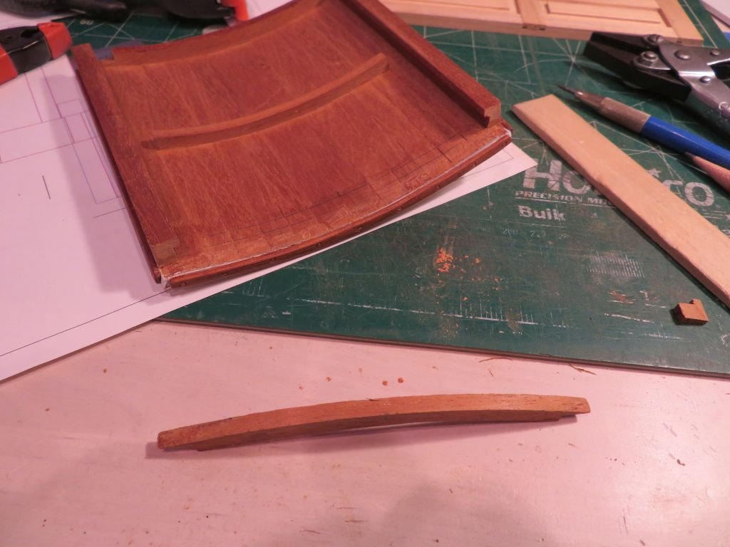
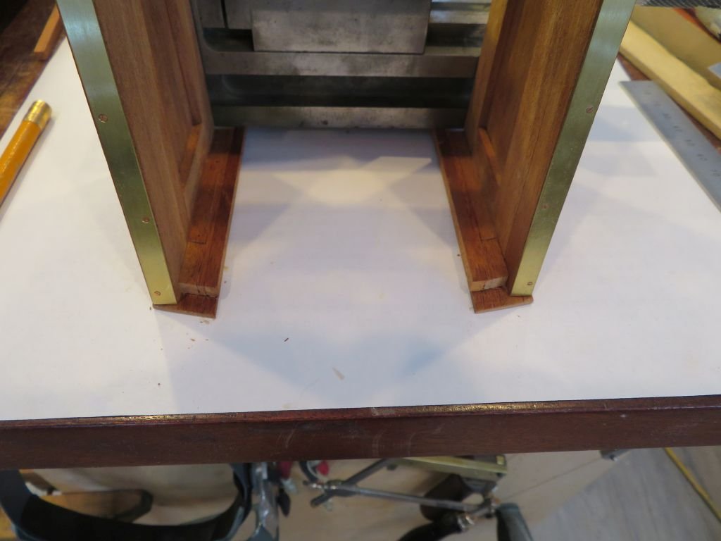
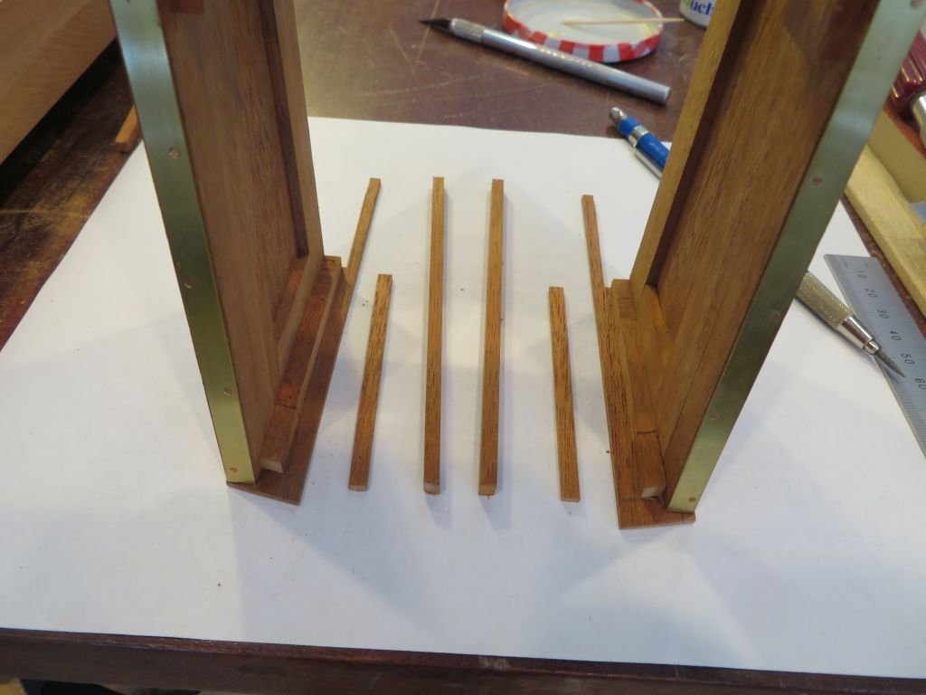
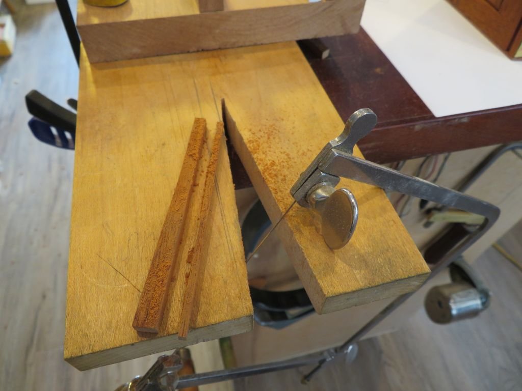
Thanks for the comments and likes, The are encouraging. As the work continues with the refit of the cockpit cum companionway. I needed to add enough wood to create the jams for the doors I cut up some small strips with the jewelers saw, it seems to be just as fast as setting up the table saw and wastes far less wood, and I am loath to waste Mahogany anyway. A couple of strokes with the Veritas low angle block plane on the thicknessing jig to prepare them for gluing. A stop was added after the filler pieces had been glued. I still need to add the piece across the bottom, and then I noticed that the back beam across the hatch was going to interfere with the top of the doors so out with the alcohol. Reposition the part after a bit of clean up. Now the stage it set for the doors. Yes I noticed the scratch and the misaligned screws. Michael
-
Papegojan 1627 by mati - FINISHED - 1/48
michael mott replied to mati's topic in - Build logs for subjects built 1501 - 1750
Good to see that you are back to your build Mati, sometimes these things take a back seat to other projects. Michael -
Hi Eric just signed up I am really looking forward to your presentation. Michael
- 599 replies
-
- 3
-
-
- sidewheeler
- arabia
- (and 4 more)
-
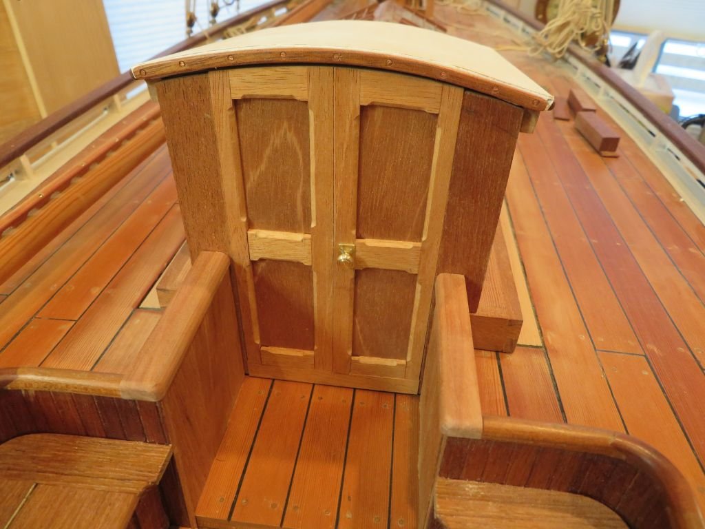
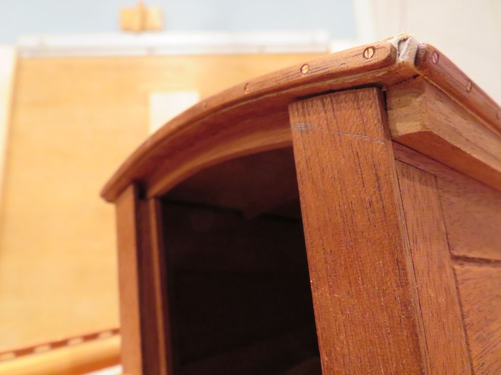
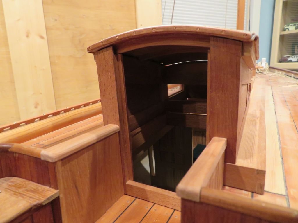
The rebuild of the companionway is starting to come together. The walls are a sandwich of Maple and Mahogany with an Apple cap rail. The companionway will go back to having doors like these ones. Michael