
Overworked724
-
Posts
1,263 -
Joined
-
Last visited
Content Type
Profiles
Forums
Gallery
Events
Everything posted by Overworked724
-
 Interesting building board! Did you make it or was it manufactured?
 -
Looks great, Jamie! Coming along very nicely. The sanding never seems to stop, does it? 😃
-
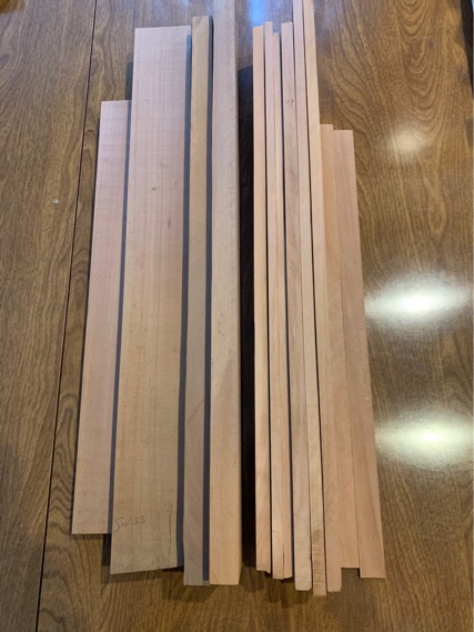
A shipmate from my ship model club was liquidating some of his stock. I jumped at it...but I was on a waitlist for good unfigured Swiss Pear from Gilmer Woods. It’s rare but they are pretty good. I get boxwood from them.
-
Yep. It almost cycles through a 90 degree angle from vertical at the stern to mid ships then back to vertical. I used those soft plastic clothes pins a lot as well as the modified binder clips. Made it easier.
- 436 replies
-
- 1
-

-
- Syren
- Model Shipways
- (and 1 more)
-
I finally got a stash of Swiss Pear wood! It’s like an early Christmas!!!! My desk furniture awaits my Christmas Holiday break!
-
Yes I did. If it has a ‘curl’ or upward swish at the bow, you will get crowded quickly and the planking becomes quite difficult.
- 436 replies
-
- 1
-
-
- Syren
- Model Shipways
- (and 1 more)
-
I think the 0.025 rope from Syren looks great. Nice job on the long guns!
-
Pg 10 of my build. Great stuff. I used my patented finger tip applicator (finger) on most applications. 🤣
-
I put in the my blog a few pages on. Great stuff.
-
Looks about right!!! My primary weapon was the finger clamp and old episodes of MASH while I waited for the carpenter’s glue to set. 🤣
-
Justin, I think your cap rail turned out sparkling. Tricky fit that. I think it looks splendid! Very clean build so far! Like how nicely your wales turned out, too.
-
See my build. Had same problem...just went with it. 👍🏽
- 436 replies
-
- 1
-
-
- Syren
- Model Shipways
- (and 1 more)
-
You can apply tung oil after you’ve sanded. But you can add coats later after finishing too. Tung oil is versatile. 😎
-
Yes...I’m a romantic.
-
No...I’m not dead. Just busy. Work hitting me from all sides. Glad to be busy...wish I could afford to retire. The Admiral would love to throw me in the ‘Shipyard Brig’ and feed me under the door like the Count of Monte Christo! 🤣 But she’s happy knowing I’m in the shipyard...where all worldly stress melts away to be replaced by stresses of a different kind.... Where time stops in the shipyard as it proceeds at its normal pace outside the door. My personal little universe of impossible problems followed by brilliant solutions...of horrible failures followed by miraculous recoveries...of stupid ideas born out as ingenious discoveries... ...This royal throne of an armchair nautical historian, this sceptered workbench, this studio of majesty, this seat of Poseidon’s memory, this other Eden, this demi-paradise, this galleon built by History just for me, a bulwark against infection and the hand of worldly concerns, this little heaven, this precious bay set in the silver sea of troubles, and serves as a defensive moat for this beloved house against the envy of less happier people... My blessed plot... My earth... My realm... My...SHIPYARD!!!! (compliments to Shakespeare’s Henry II)
-
Bloody Awesome!!! Seriously...I think I just peed a little in my excitement. That is simply brilliant!
-
Looks like a similar ratio I used. I used Tamiya red and Tamiya desert yellow at about 5:1. You get that nice deeper reddish maroon. Like blood. Looking good!
- 436 replies
-
- 1
-
-
- Syren
- Model Shipways
- (and 1 more)
-
I wish I’d added a bit more. You can always sand down extra meat. Something you can’t do if there is a gap. I did have a slight gap at the terminus of the stern planking where the counter begins. It made it more difficult to lock in the planks and also can lead to a misshapen area which needs wood filler and sanding. (Which mine did). I would read other logs and meditate a bit on the planking book, but in the end, I think you’ll make the best decision for your ship. She’s looking very trim! 👍🏽
- 436 replies
-
- 1
-
-
- Syren
- Model Shipways
- (and 1 more)
-
Outstanding! Yep....filing the bell was a nice idea. That piece really shines!
- 950 replies
-
- 1
-
-
- syren
- model shipways
- (and 1 more)
-
Flat screen TV with satellite dish!!! (Kidding) brilliant work!!!!!
- 950 replies
-
- 1
-
-
- syren
- model shipways
- (and 1 more)
-
Toothpicks for the win! I used them on the Sultana in same way. Nice modification!!!! Looks beautiful.
- 157 replies
-
- 1
-
-
- model shipways
- syren
- (and 1 more)
