


bartley
-
Posts
406 -
Joined
-
Last visited
Content Type
Profiles
Forums
Gallery
Events
Posts posted by bartley
-
-
6 hours ago, oldmate said:
Sweet, I've been delayed for some time now on my cheerful build. However, seeing this post inspires me to get back at it. Thanks
Thanks, oldmate. Yes I have been a bit on-and-off on mine. Other hobbies. Other builds even. But you should persist. It's a great build. For me, lots of challenges. But all can be overcome and very satisfying then.
Cheers,
John
-
I have made fine furniture for many years and have used both, On open grained timbers wipe-on-poly can look quite good if you wipe it off quickly and it is very durable so it is good on surfaces which will be subjected to wear and tear. However, in my opinion, there is no comparison to the patina of shellac. As someone else said, it becomes richer over the years. It is, after all, French Polish although you could not apply that technique to a model. In fact when I apply shellac to a model I wipe it off quickly just like you would with wipe-on-poly,
If you do a side-by-side test on whatever timber you are using you will probably not see much difference. I t will only be when you look at it a year or so later that you will start to see the difference.
John
-
Shellac for me as well. I don't like the "synthetic" look of wipe on poly.
John
- Canute, thibaultron and mtaylor
-
 3
3
-
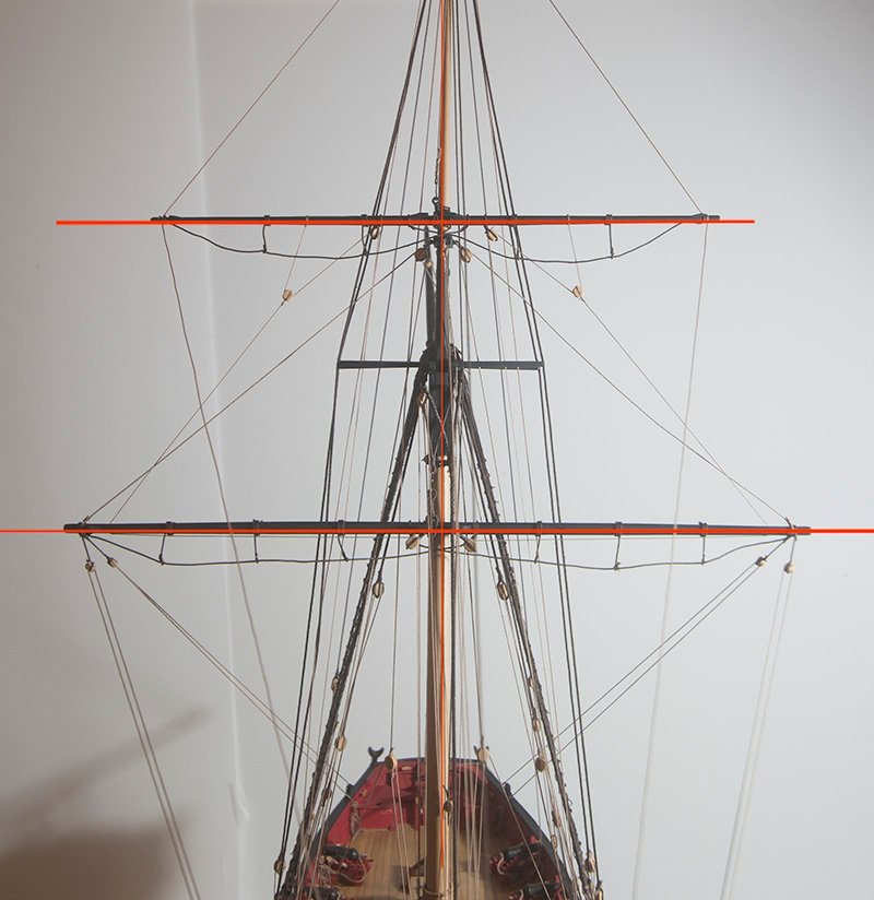
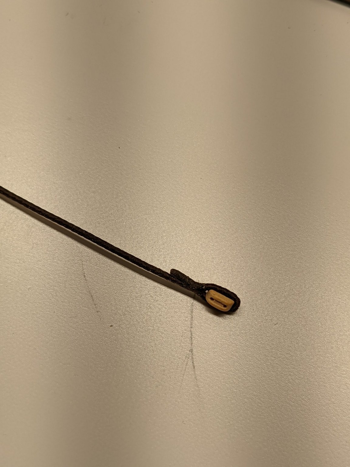
Post 69: Installation of the Topmast Yard
The first task was to attach the truss, which was seized around the mast to hold the yard in place. Attachment of the halyard was straightforward. A hook was seized to a length of 0.63 mm rope which was attached to the sling.
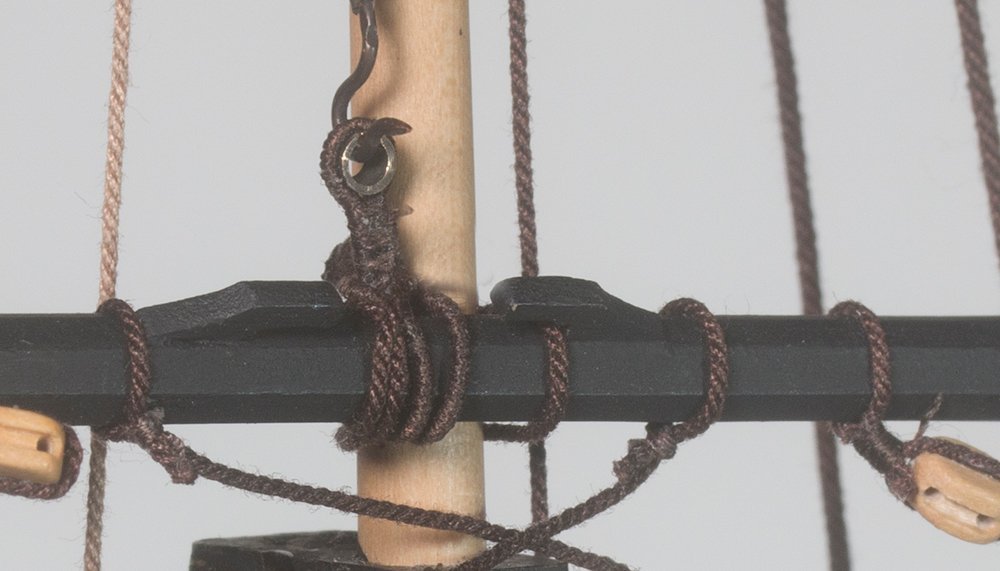
It was then led down to a tackle on the starboard side which was an exact mirror image of the topping lift tackle on the port side:
Aligning the yard proved more difficult than I thought. First I fitted the clue lines and sheets since these were the inner ropes. I then used the tension on these to establish the correct angle for the yard. However since these also connect to the main yard tenshioning of these caused movement of both yards.
So in the end I left these slack while I adjusted the angle with the lifts and braces and the re-tenshioned the sheets and clue lines quite loosely later.
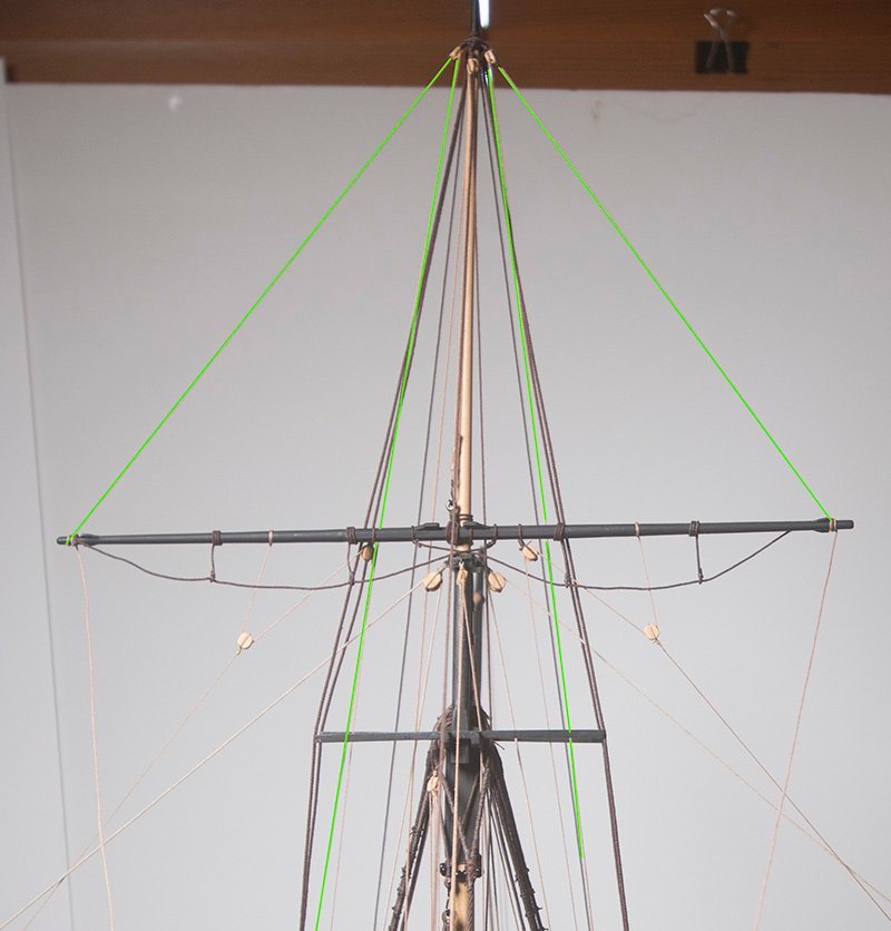
My alignment eye was checked with a laser level:
John
-
On 9/24/2021 at 7:28 AM, PRS said:
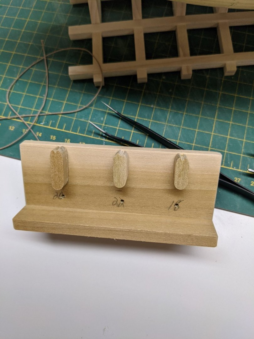
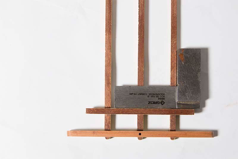
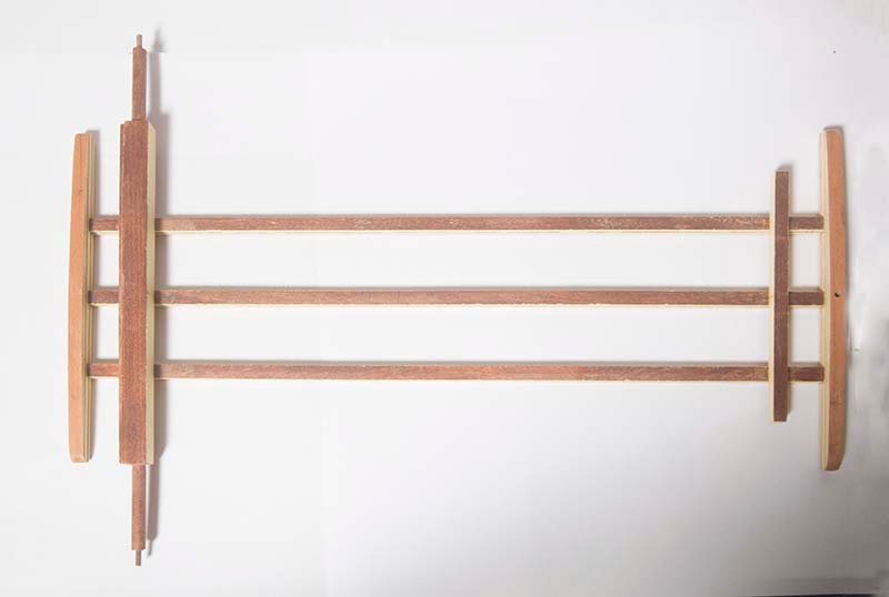
At this stage I made myself a jig for making rope coils.
There are three different sizes.
Paul,
I like the look of these jigs. The only thing I would say is that 26 mm is a pretty big coil. When these are made in practice one holds the rope in each hand then stretches the arms out letting the rope slide through then bring the hands together to make a loop if this makes sense. The point is that the diameter of the loop is about half of your arm span. On our boat our coils were around 800 mm give or take, so you can work out what this would be at scale - around 16.5
Anyway, your model is looking great. A step above mine, I think
Regards,
John
-
On 9/22/2021 at 7:21 AM, PRS said:
So making the Burton Pendants I first siezed the rope the full length and then siezed the block onto it. This didn't look right to me so I redid them.

I then did the whole seizing after putting the block on and then wrapped the rope from the block up. Was a simple matter to tie some rope on the block to hold one end. I am hoping this is the right way for these.
Paul,
I agree that wrapping the serving over the seizing looks better. For what is worth, I am now using Mara polyester thread for serving. I found the cotton thread was a bit furry and Mara gives a smoother result in my opinion. Because I am winding my own rope I have this in various sizes and I like to use thinner serving thread on thinner rope. If you use 50 wt thread on say 0.45 mm rope it almost doubles the diameter. This looks wrong to my eye.
Regards,
John
-
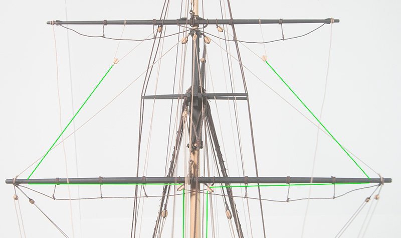
Post 68: Installing the Main Yard
I have spent some time doing a final tidy up some of the belayed lines and trimming them off. Now it is time to install the main yard which was constructed some time ago. In principal the lifts control the vertical tilt and the braces the for and aft tilt. However, because the braces exert a downwards force I found that they really control both movements. I initially squared up everyting by eye but the laser showed I was a little off and helped me to be more precise:

On the whole I am pretty happy with the way it looks but nothing is tied off permanently just yet and obviously the lifts are yet to be belayed.
John
-
Sorry for hijacking Paul's thread but I tried to give some guidance on serving issues here. It looks like Paul is using Gutterman 50 wt but lets wait to see if he confirms that/
Regards,
John
-
1 hour ago, DaveBaxt said:
For the record what is the percentage of mix of this stuff to water and how long does it take to pickle before soldering and blackening? Best regards Dave
Dave,
Use about 1 part metabisulphite (Sparex} to 7 Parts water. It is not critical, Add the Sparex to the water. Mot the other way round as it can be dangerous. Operation at 60 degrees Celsius for about 10 minutes is sufficient. Don't prolong the treatment because it is actually Itching the surface. If you want to dispose of the Sparex pour it slowly into a bicarbonate (baking soda) solution. It will fiz so do it slowly. You can then dispose of it down the drain, Wear gloves and eye protection throughout. It is not really dangerous chemistry but you don't want any of these things in your eyes and the blackening solution is actually poisonous,
Regards,
John
- BobG, thibaultron, Canute and 1 other
-
4
-
1 hour ago, DaveBaxt said:
Thank you for the link john. I think that was the first thread which got me onto this Pickling before blackening idea. Best regards Dave
Dave,
A couple of extra hints. The exact procedure you need to use depends on the state of the brass. Some is treated with lacquer and the purpose of the acetone is to remove this. Look at my post here. On the other hand if the brass has an oxide coating (which it usually does) acetone will not remove it. In this case you need to use metabusuphite ( Sparex). So a safe procedure is to do both. I use acetone first and then metabisulphite. If your brass is clean it should only take about 15 sec to blacken. If you leave it longer it will develop a flakyness which will rub off. You can terminate the Sparex cleaning with bicarbonate. Then wash with water.
In case you are interested I dealt with the chemistry here.
John
- Canute, thibaultron, mtaylor and 1 other
-
4
-
On 9/15/2021 at 7:12 PM, DaveBaxt said:
What are the guys using for cleaning brass before using Brass black . I read on hear that some people are using Sparex in the US but unable to source this in the UK. Any alternative out there in the UK. I am also confused as to why some people are using sodium bicarb to neutralize the Pickling agent and then Acertone afterwards. The last bit is what confuses me , Why would you then use the acertone after the sodium bicarbonate ? Best regards Dave
Dave,
There is lots of info on this site about this - including stuff from me!. Search for "blackening revisited" for example.
John
- Canute, mtaylor and thibaultron
-
3
-
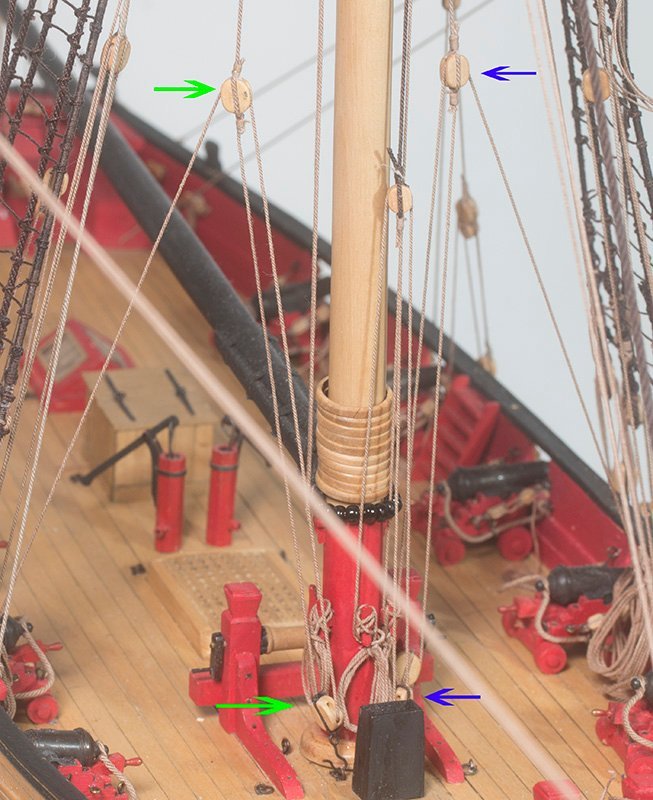
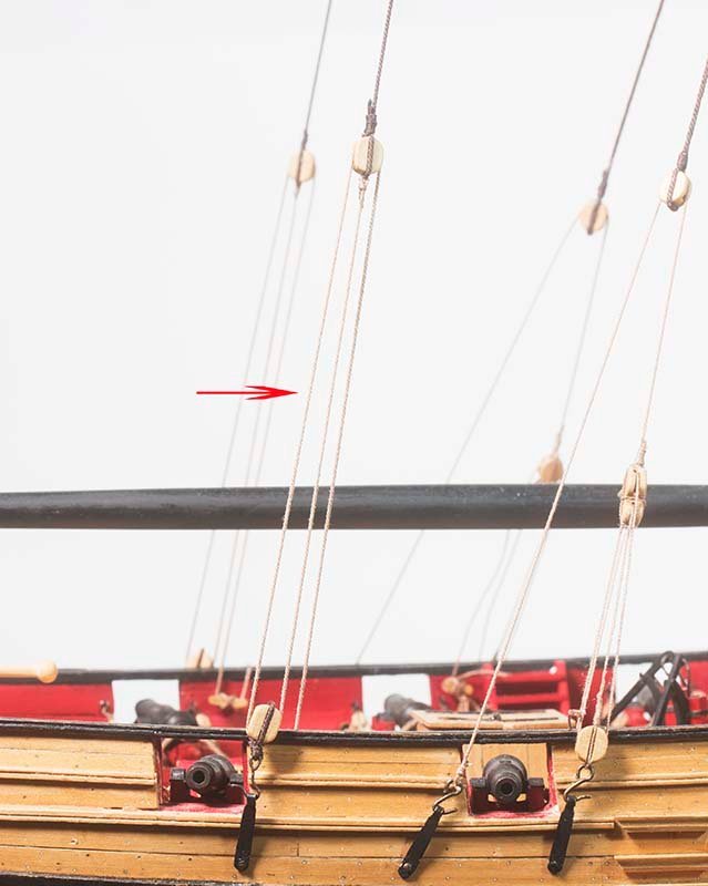
Post 67: Topmast Backstays
Chuck points out that on contemporary models these are seldom shown as rigged. I decided to rig mine for two reasons. First a practical one. If the topmast sail were deployed then the physics would demand that these backstay swere rigged in order to avoid damage to the topmast itself. The second reason is, I suppose an aesthetic one. If they are not rigged the aft chain plate is vacant.
These run from the upper topmast to a block above the deck. A tacle is then rigged tpo a block attsched to a hook on the chanplate an thence to a cleat in the aft of the ship.
John
-
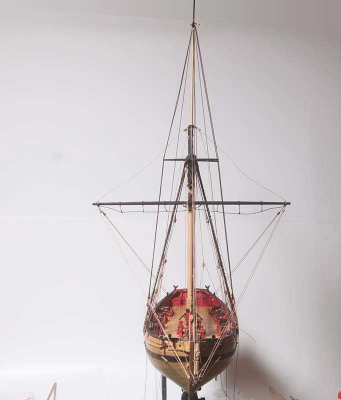
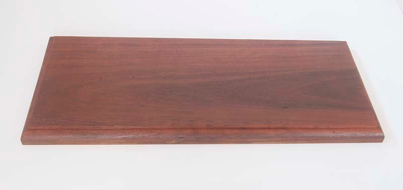
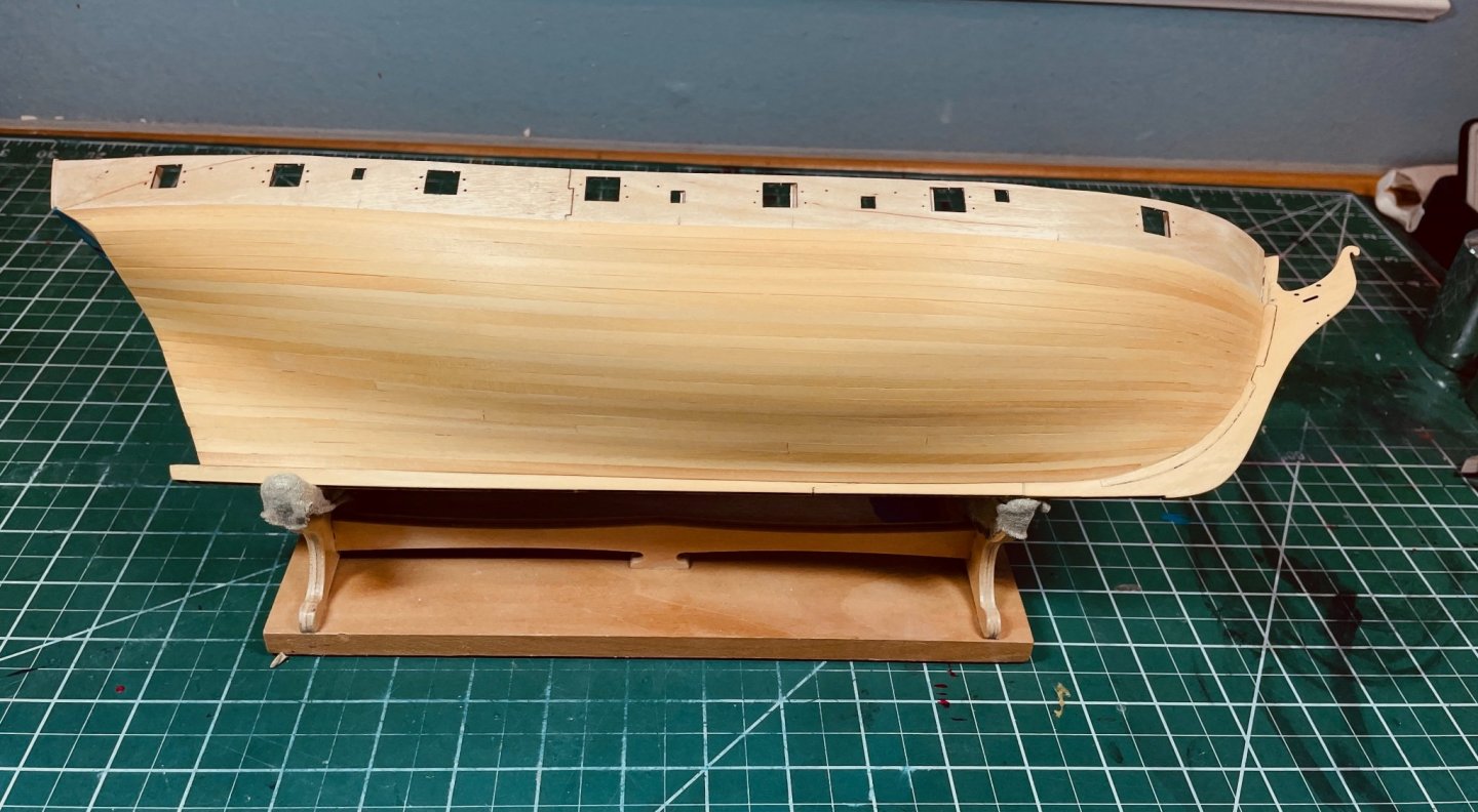
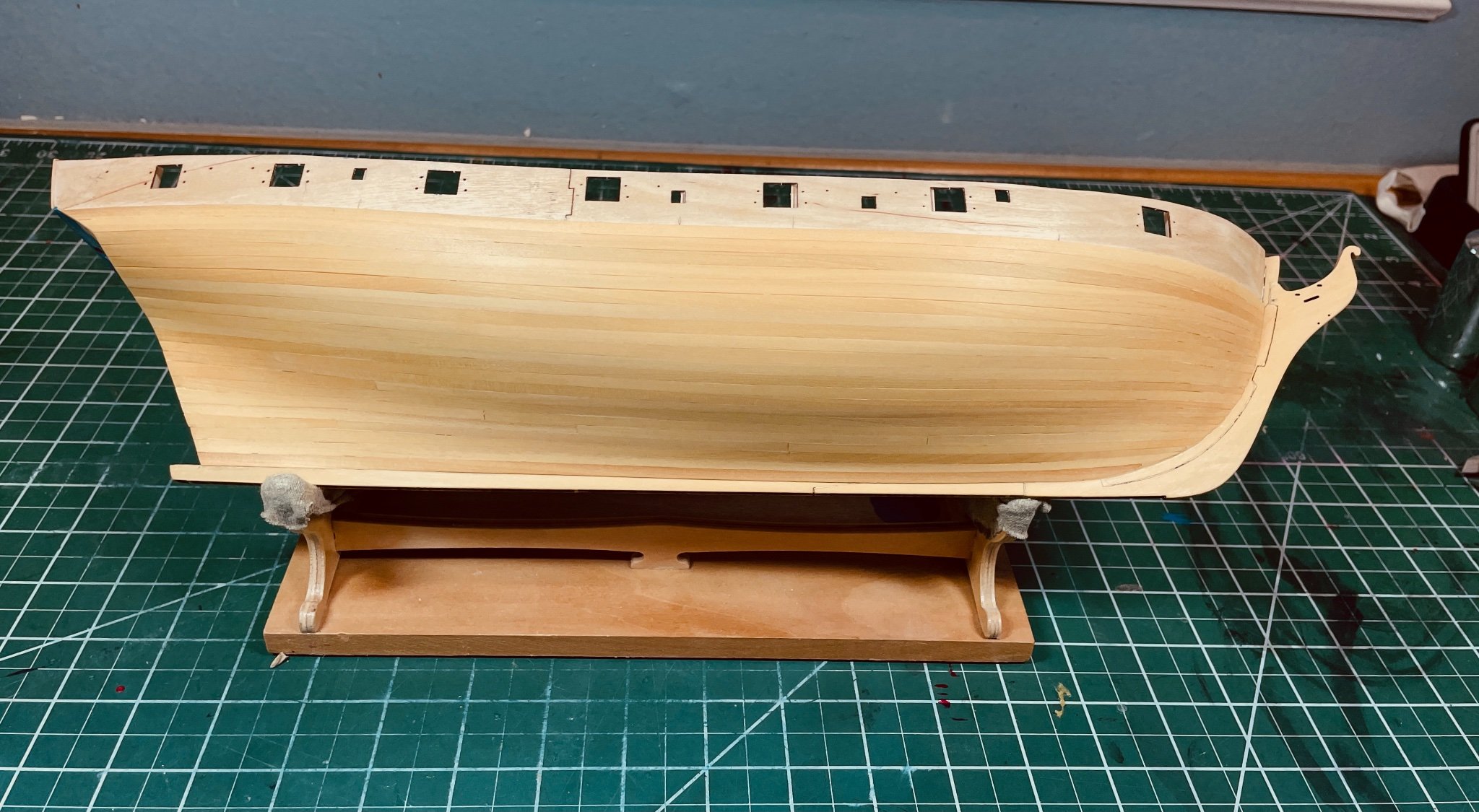
Post 66: Mounting
Before proceeding further I felt I should finalize the mounting on a plinth. Captive nuts to take 1.4 mm brass threaded rod had been installed at the start of construction and the rod was now monted into these nuts:
The plint was made from a plank of Australian hardwood which was given three coats of Danish OIl
I have available the brass pedestals which many use:
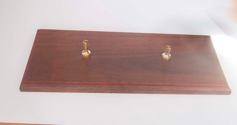
However for a wooden ship I prefer small wooden cradles. I was able to get the profiles pretty close because the mounting nuts were adjacent to bulkheads. These are just mock-ups at this stage as they wil eventually be the same colour as the plinth:

So here is the ship mounted on the plinth:
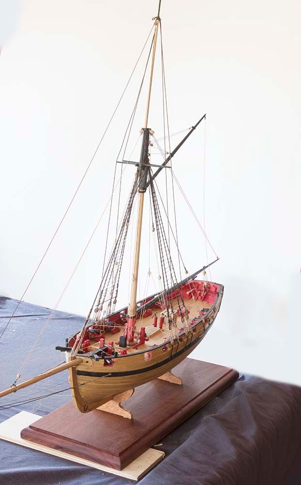
And the laser level indicates that the past is vertical with respect to the plinth:
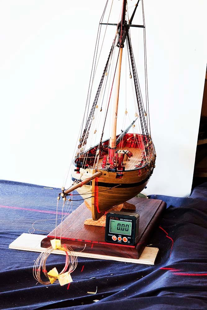
Next step is to install the yards whch were fabricated earlier.
John
- JpR62, GrandpaPhil, bruce d and 3 others
-
6
-
Glenn,
Just one further thought. Be careful with chucks on these devices . They are quite massive compared to the device itself and sometimes do not run true for small bits. They tend to precess so the drill does not run radially but describes a small circle. So you may be better off with collets or use a Kyocera bit because they have 3 mm shafts.
John
-
On 8/18/2021 at 2:29 AM, glbarlow said:
Where did you get your drill? I’ve been looking for something like this for a while.
Glenn,
I have used a Wecheer for some time now. It is rechargeable and has six speeds. The slowest very slow (about the same speed yo would use with a pin-vice) and great for working directly on the model where my Proxxon would be too large and aggressive. And it is very small (only 140 mm long).
John
-
On 9/2/2021 at 8:29 AM, glbarlow said:
I’m not thrilled with the uneven color of the boxwood. I spent a lot of time sorting pieces to color match then the WOP found whole new colors to display.
I actually like the variation in colour. I think it is closer to what real ships look like. In my opinion, when the planking is uniform in colour I think it looks a bit "plastic"
John
-
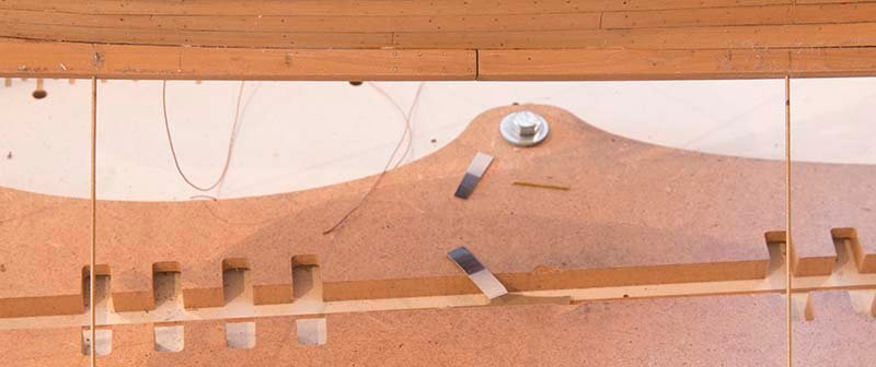
Brake Assembly Part 2
Before the brake assembly itself is installed, I glued on the forward anchoring bracket and the rear axle bracket to the chassis:
The first part of the braking mechanism involves installing a metal bar which rotates to move the brake push rods . This bar is made from 2 mm diameter brass rod and needs to have 2 1mm holes drilled through it to connect to the push rods. I did this using a mill and a V block:
The three clamps to hold this rod to the chassis were fabricated from 3mm brass strap:
The instructions have this rod sit on top of the chassis breams but I chose to inset it slightly with a round file in order to locate it more firmly:
The next task was to make the brake bar clamps - once again from 3 mm brass strap:
These are nailed to the chassis beams. They are wider than the brake bar in order to allow it to slide:
The final assembly will look like this:
The next task is to construct the brake lever itself but I need to pause on this build while I return to complete my Cheerful build. I have been making a plinth and some rope for that and those tasks are now completed.
John
- marktiedens, mtaylor, Jack12477 and 12 others
-
15
-
7 hours ago, dodgeyhack said:
Great job so far! Your Cheerful, and her fine details all look really well crafted.
My starter kit arrived today, and it will be my first build, so I've really appreciated some of your more detailed descriptions of the processes you took and your discussions on tools. It's been very helpful (being relatively local, thanks also for the pointers on suppliers). I particularly love your home made lathe! I have been mulling over in my mind how well something like that would work.
Thanks for your comments about my cheerful, Yes, for me the home made lathe works well but you have to be careful that everything is aligned. I bored all the boards in a stack and then the drill has to be clamped pretty well and must align with those holes. After that it will work well. I do have some larger bearings which I got from a local supplier but for the most part the cheap roller blade bearings work well. The Proxxon wood lathe is priced well but I did have a few issues with it which I think I mentioned in my post. I will be returning to Cheerful in a few days. I have been making a plinth and some rope and also started a build on a stage coach to try something different.
Cheers,
John
-
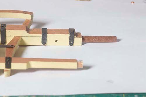
Brake Assembly
The brake shoes are glued to the brake bar after making a cleft in the brake shoes as they would have been assembled in two parts.
The two push-rods are then nailed to the brake bar:
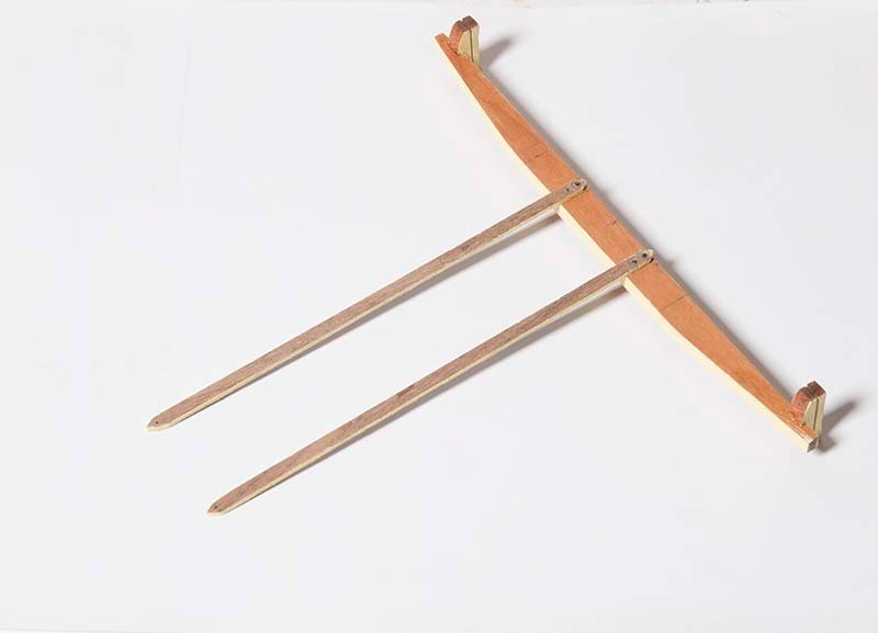
These will be assembled onto the main chassis in due course.
John
-
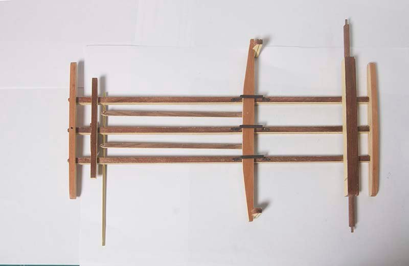
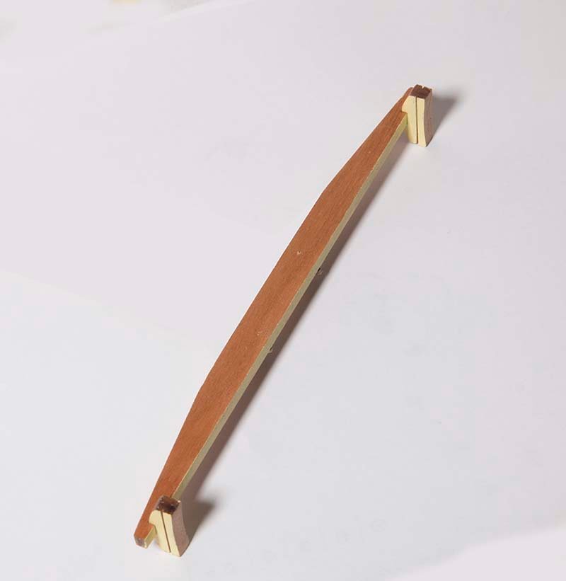
Steering Mechanism -Part 2
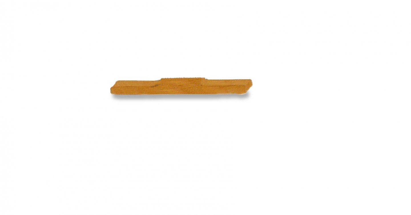
Quite a complex piece of woodwork this and it had to be strong because the horses were directly attached to this unit. First the axle bracket is made by gluing together two 4 mm parts Rebates are then cut into this unit to fit into the steering bars:
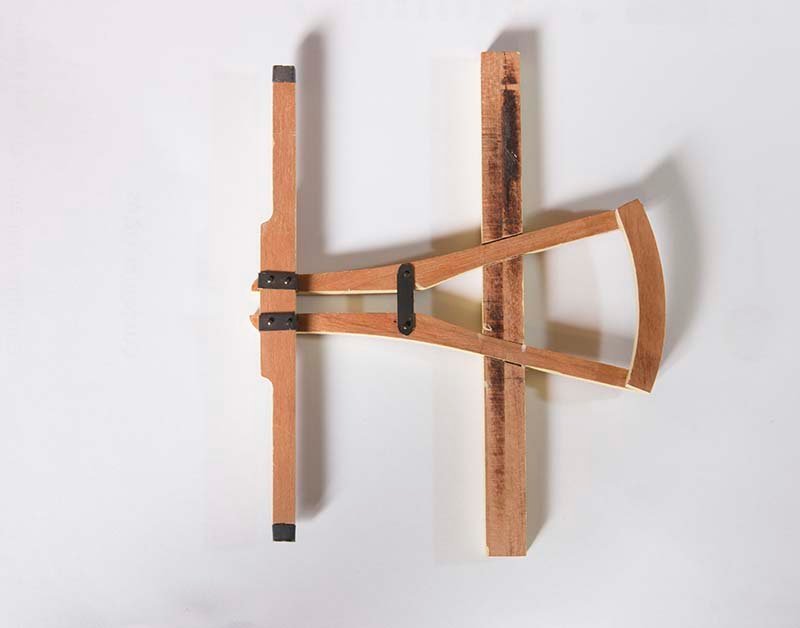
on top of this is glued the steering bar:
I neglected to photograph this stage but here is a photo of the unit after the metal clamps are added:
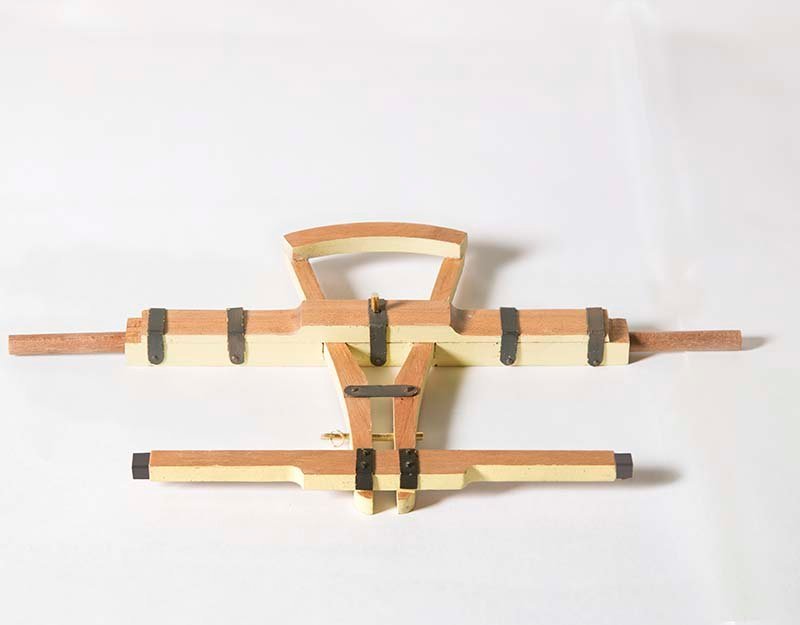
The nest task to to add the metal struts which strengthen the haul bar. These run between the axle bracket. and the haul bar, Drilling the hole in the axle bracket to take these was tricky because no pin vice I had would fit between the two beams:
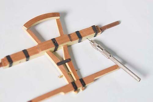
Finally, both metal struts are in place to complete this unit:
.jpg.a87a907bbab299e18550170a179b2821.jpg)
John
-
Yes Paul, I am a great fan of Vallejo paints as well. A good range of colours and, as you say, excellent brushing characteristics, I spray them when I can. As you know there "Game Air" range is designed for spraying but I mostly use the "Model Color" range. For brushing I dilute them by about 50% with their thinner and apply several coats. It is then hard to tell the difference between brushed and sprayed in my opinion.
John
-
Glenn,
As a sometime painter this variation in a colour of the same name from different manufacturer is very common. Names are just a guide. there is no standardization. These days some manufacturers specify the Pantone reference or the CMYK values (which of course you can reproduce in Photoshop) and you will find they are very different. Many colours are still made from naturally occurring minerals. Red and yellow ochre for example. You don't have to travel very extensively to know that the ochre cliffs in different geographic regions vary enormously in colour. So the source a manufacturer chooses for his pigment will affect the resulting colour. So you will find "yellow ochre" varies enormously from one manufacturer to the next.
John
- Rik Thistle, Canute, mtaylor and 1 other
-
4
-
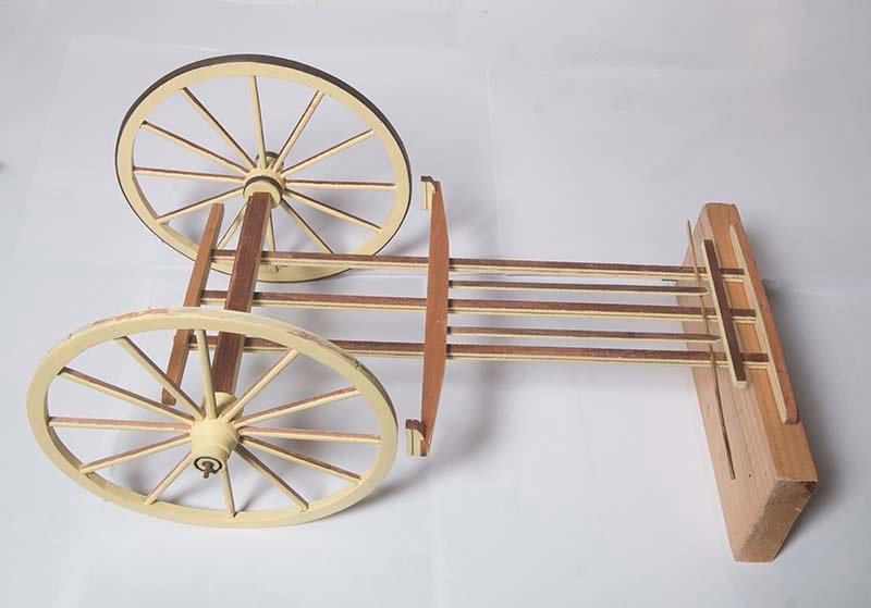
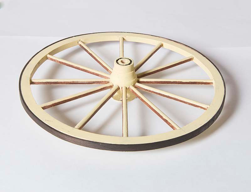
Wheels Part 2
In view of all of the information above about swaging, I thought it was time to but some "steel" treads and hub supports on my wheels.
The tread is 5 mm X 1mm walnut which was bent into a rough curve using heat and a little water. It was stained with Japan Black spirit based stain and then glued to the rim of the wheel with CA:
Reinforcing bands on the hubs were made from 4 mm brass strip. This was curved to shape using a mini rolling mill:
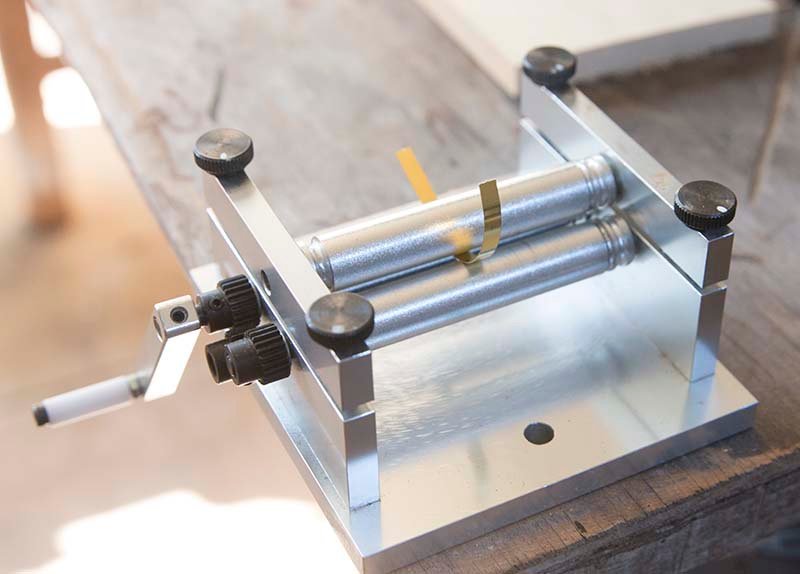
A curve close the the correct diameter could be produced:
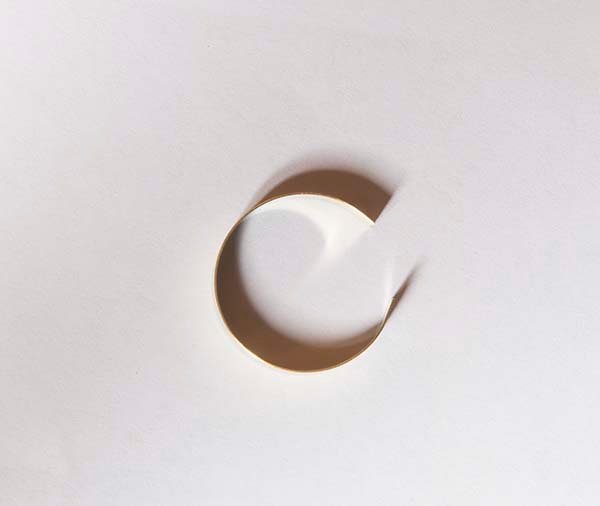
The final shape could then be achieved by simply squeezing together a little more by hand. These bands were glued to the hub with CA. All of this metalwork was then blackened and weathered a bit so it looked like iron.
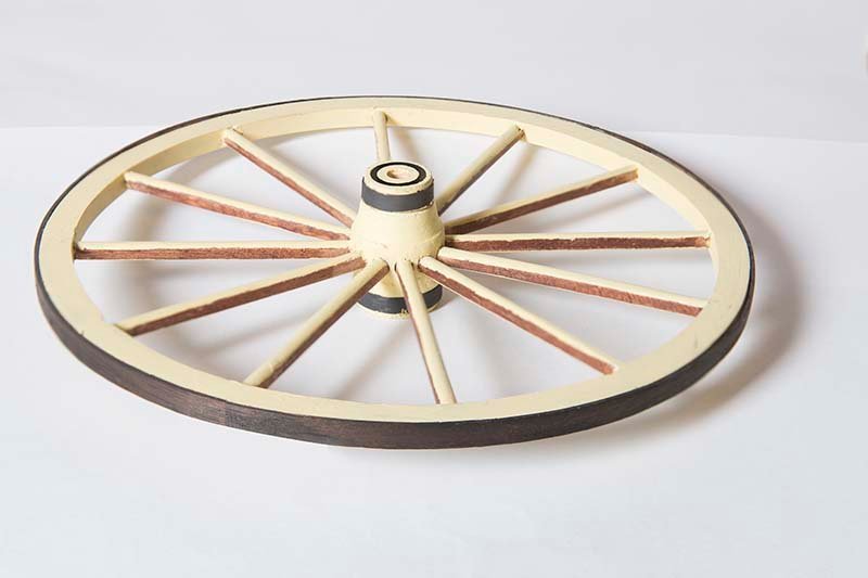
This only one wheel - three to go! I also need to insert simulated bolts into the rim at each spoke position but I think I will complete my steering gear first.
John
-
Fascinating background information guys and thanks for all the likes. I am pleased there is so much interest. I thought that on a shipping site there might not be much interest in this project. I might need to lift my game!
John
- bruce d, popeye the sailor, Canute and 4 others
-
7


The Kriegstein Collection
in Book, Monograph and Magazine reviews and Downloads. Questions and Discussions for Books and Pubs
Posted
It is good that you are able to deal with them. WE have a problem in Australia with Amazon , Google and Facebook. They refuse to pay our income tax for business they do here and will not pay our media companies for the news that they use. So most of us use alternatives which in the case of Amazon are not so extensive.
John