


bartley
-
Posts
424 -
Joined
-
Last visited
Content Type
Profiles
Forums
Gallery
Events
Posts posted by bartley
-
-
-
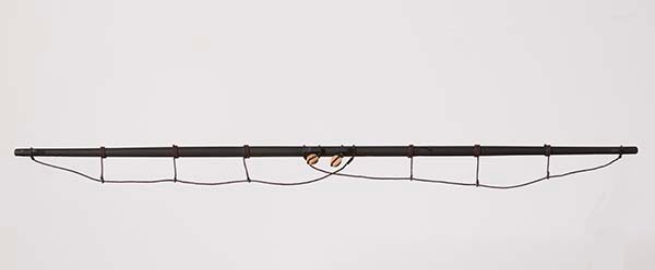
Post 65: Construction of the Yards.
Work on Cheerful has been slow of late since we have only just returned from a six week holiday to the north of our state. And now we are embarked on some major renovations. Nevertheless, I have found time though to start work on the yards,
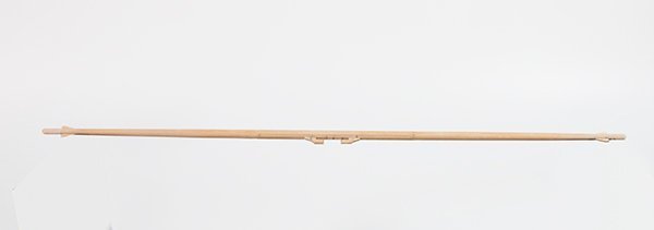
The yards were turned on my home-made lathe. It may be of interest to know that we did originally consider the Proxxon DB 250 lathe which we were able to assess at our local supplier.
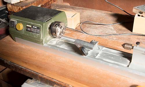
However, we felt there were some limitations:
1. There was no provision for a central support.
2. The speed control seems to be a simple rheostat so the torque at high speed was very poor.
3. The bed length is quite short and the much vaunted hollow headstock was, we felt, limited because if the work-piece was extended more than a few centimeters into the headstock considerable whipping occurred even on round dowels.
4. The tool rest is very short and the adjusting handles obstucted the tools.
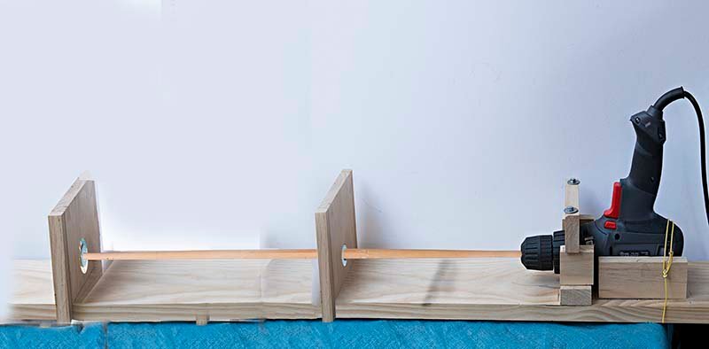
I felt I could address some of these issues andconstruct a superior tool using a simple power drill as shown here.
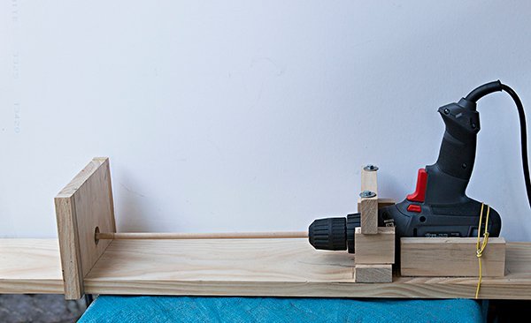
I use a switch mode power supply to control the drill speed and find that this provides quite uniform torque. A colleague has adapted my design by incorporating a belt driven motor and obtains even better performance.
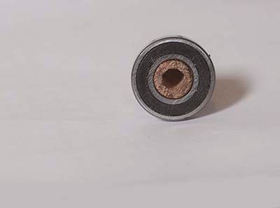
A feature of this design is that the length of the work piece is not an issue and the tail-stock (which consists of a roller blade bearing) is hollow and can be clamped in any position. The original idea was to extend longer work-pieces through the tail-stock. I now find that using a central bearing obviates the need to do this and I now only extend the work through the tail-piece in order to turn small diameter ends of spars and masts. The present task is a case in point. Since the central region of the yards is octagonal the central bearing insert was made octagonal using the FF 230 mill.
After turning the yard:
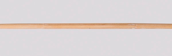
the stop cleats were fashioned from 1/8" sheet
After painting black the stirrups and footropes need to be installed.
In his monograph Chuck suggests the stirrups should hang below the yard by 11 /16 “ This equates to17.5 mm. However, the plans show a much shallower distance than this. I spoke to Chuck about this and he said that he obtained conflicting advice on this issue and on the model he “split the difference”.
David Antscherl in his book suggests that the footropes should be 3’ below the yard and that this can be achieved with stirrups of 2’ 9” This equates to 17.4 mm at the model scale.
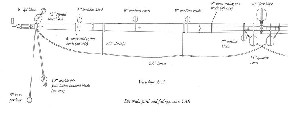
This seems excessive since my waist is only about 3' from my feet! In the end I elected to make my stirrups hang 12.5 mm below the yard.
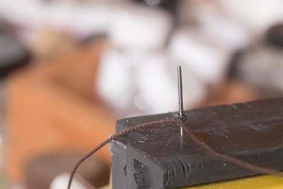
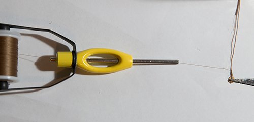
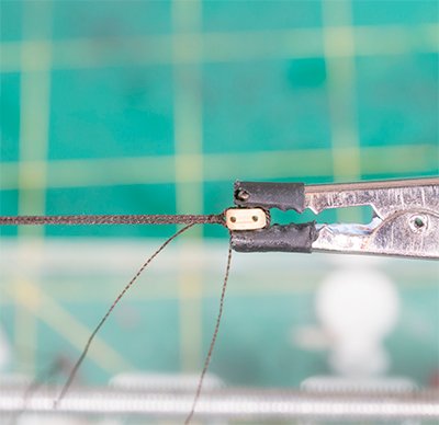
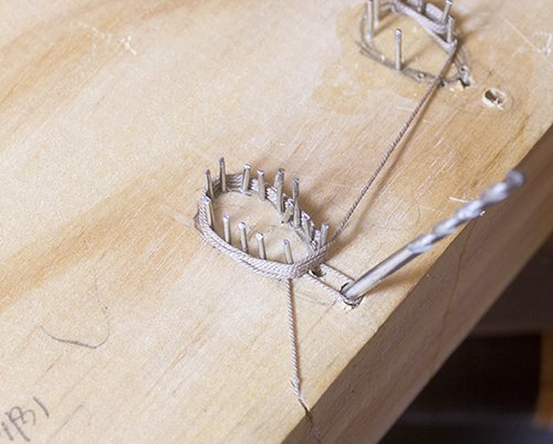
The Stirrups are made from 0,63 mm rope by first forming a loop by using a needle to draw the end through the main strand then tightening this around a 0.8 mm drill bit
.
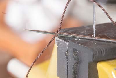
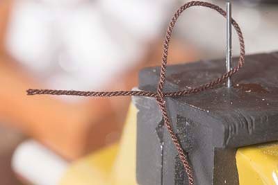
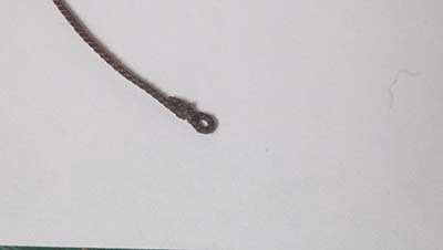
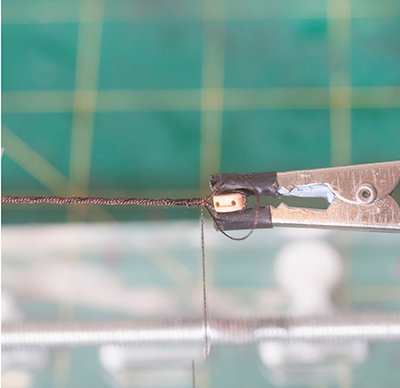
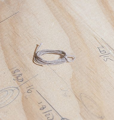
The loop was sealed with shellac and a small seizing added
These are then suspended from the aft end of the yard using a copper wire to keep them at the same length
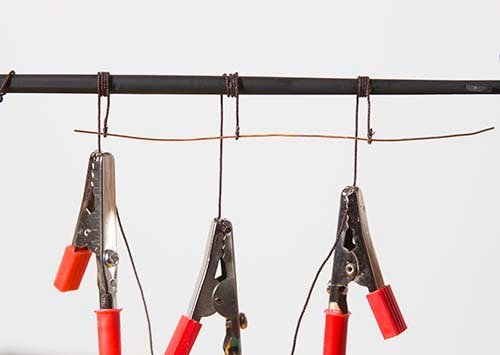
Finally the horse was threaded through the lools and seized to the yard as indicated in the plans.
-
Post 64: Topmast Stay
Chuck points out that these were not always rigged but he chooses to rig one himself and I propose to do the same. I will also rig the topmast back stays as it would seem to me that the physics demands neither or both to balance the forces. Also if the topsail is rigged then most of the time the pressure would drive the mast forward and demand back stays be fitted even if te leeward one is slackened in practice.
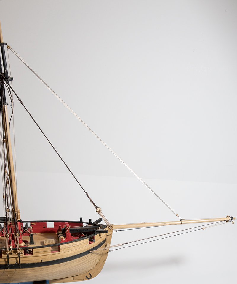
So the topmast stay starts with a seizing to the end of the bowsprit:
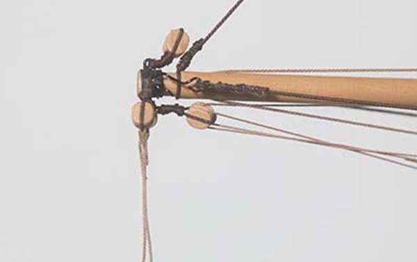
this tip of the bowsprit is a pretty busy region. You may recall that four blocks were fitted here much earlier:
and there are also two hooks for the bowsprit guys and now this new seizing. (Incidentally the ropes attached to the 3/16 single blocks will form the braces for the main yard. They have been sitting there fro a couple of months!)
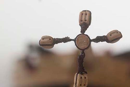
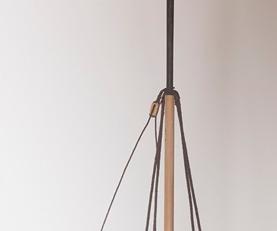
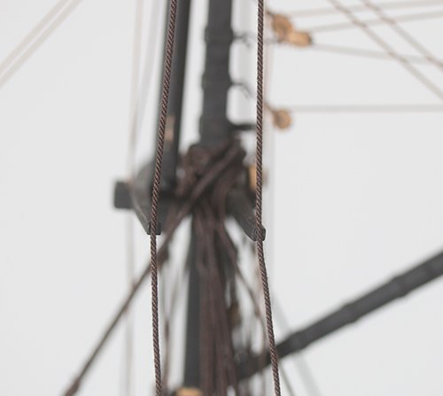
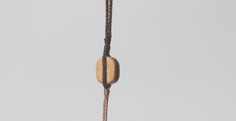
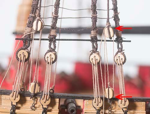
The stay then travels through a block seized to the topmast:
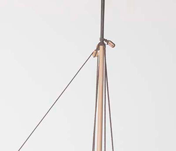
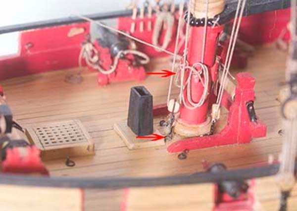
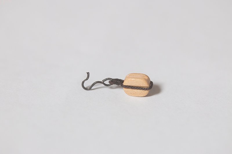
Then down to a tackle block here:
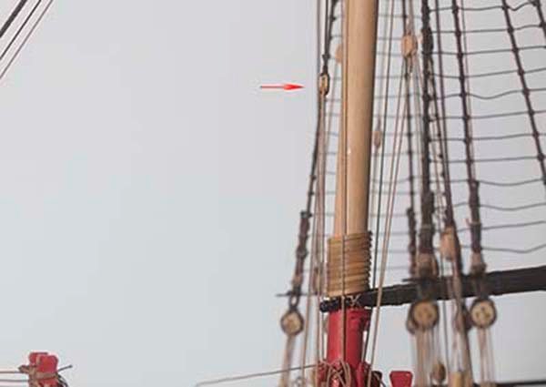
This tackle passes through a block hooked to the base of the mast and is finally cleated at the front of the mast, as shown by the red arrows here:
The main yard will be next but there is quite a bit of work to do on that.
John
- PRS, GrandpaPhil, JpR62 and 1 other
-
 4
4
-
Thanks for your comments on the weathering, Glenn. I take your point that the effect here is much more subtle than the applications that I am used to. Even so with the cannons, I weathered hem off the ship and I had to "handle" them later to attach them to the carriages and fit breaching ropes. Not handled with fingers of course I have som3 foam tipped jewelers tweezers. Nevertheless I did give them a spray of Dulcoat. I couldn't see any difference in the appearance before and after. but as you say in cases were the fitting is already installed coating is not possible but thenit wont be subjected to further manipulation.
Thanks for the explanation of your approach.
John
-
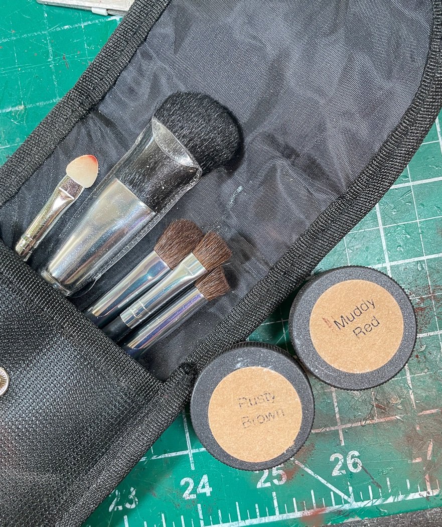
10 hours ago, glbarlow said:

The stanchions are ‘metal’ so that meant back to my process (or to be more precise the process I learned from Chuck’s monograph) for getting wood to look like metal. First my Admiralty Iron Works Black paint then to Doc O’Brien’s weathering powders and my soft brush set. The set comes with twelve different powders, I’ve only used Rusty Brown throughout my build, first on the carronade barrels and then applied to every “metal” piece since including parts of the windlass and winch and actual metal pieces for the deadeye strops and stay belays.
Great Build Glenn!
I would be interested to know if you needed to protect your weathering. In my previous modeling life involving vintage rolling stock and vintage aircraft we made extensive use of washes and weathering powders to simulate rust. We found that we needed to use a varnish such as Dulcoat to protect the weathering powder otherwise later handling would abrade the weathering. Did you feel you need to do this? Unfortunately these models were made for the museum and I am unable to reproduce photographs of these models.
John
-
On 4/12/2021 at 9:01 PM, allanyed said:
For securing seizings, knots, splices, etc. perhaps shellac (pH 7 to 7.3) is the better way to go.
Yes Allan, I use shellac a lot as well.
But this pH scale is not easy to get your head around. It is common to think that the difference between pH 6 and pH 5 is "not much - its only 1 in 5 or 20 %" but the scale is logarithmic. This means that when we go from pH 6 to 5 the acid concentration goes up by a factor of 10 and if we go to 4 i tgoes up by a factor of 100. It also means that going from6 to 6.2, the acid concentration doubles! The message is that a small difference is significant. It is also not so easy to measure particularly close to neutrality and for things that are not soluble in water, so some quoted figures may be questionable. Confusing, I know but the closer to neutrality the better.
John
- bruce d, thibaultron and mtaylor
-
1
-
 2
2
-
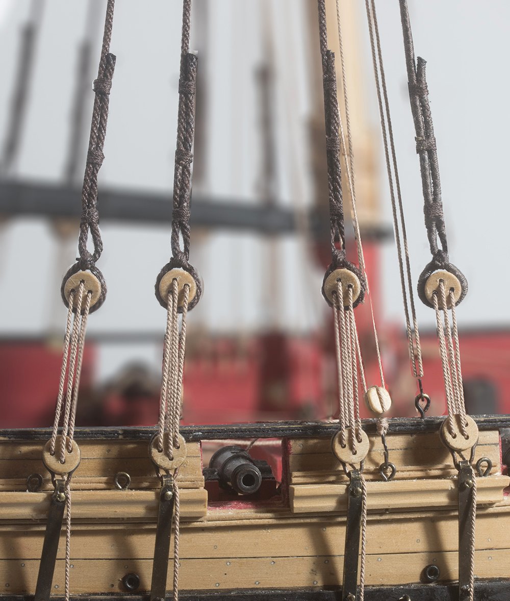
Post 63: Topmast shrouds
Ratlines are now complete and all knots sealed with shellac.
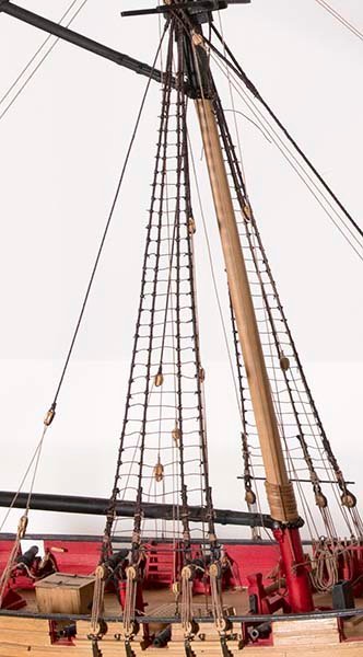
The topmast shrouds are run in pairs from the top mast
They then run down though the cross trees
In preparation for the tackle to secure these a 1/4" block needs to be seized to each shroud
and another to a hook
finally the tackle is then rigged to eyebolts on the chain plates
Next up the topmast fore stay. Chuck points out that these were not always rigged but it seems to me that if there were a sail rigged on the topmast yard then some support of the topmast itself would be required.
John
-
On 6/14/2020 at 6:43 AM, DelF said:
Super 'Phatic (which I got here) really is different to PVA. It looks different, being much thinner and more penetrating, and grabs almost as fast as CA, especially if you hold it under pressure for a few moments..
For what its worth I have done a quick chemical analysis of Super Phatic. For those in the know I used Attenuated Total Reflectance Infrared Spectroscopy (like most exclusive clubs, we scientists invent this special language to keep out the rifraf!). This technique is quick (ten minutes). It cannot usually unequivocally identify a substance but can eliminate some possibilities.
So, It is not CA and it is not PVA. It looks like an acrylic modified with polystyrene. There are other techniques which could confirm this but not really worth spending my time on really.
John
-
Make your own is, in my opinion, the answer to many of the issues raised. To a certain extent you can control the appearance to suit. Gutermann Mara comes in such a range of colours that dyeing is unnecessary, and, as I pointed out in my Cheerful build, you have matching seizing thread in sizes from 0.1 to 0.3 mm.
John
-
Seizing revisited
My Cheerful has been on hold for a while since we have just taken our annual holiday. My other hobbies have also interfered with my shipbuilding.
In the past I have used various threads (16/0 fly tying line, 50 wt sewing thread, etc).
However, since I am now making my own rope it suddenly dawned on me that it makes more sense to use the Mara thread I use. It obviously matches perfectly and comes in a variety of sizes.
For example:
Mara 220 has a diameter of 0.109 mm
Mara 150 has a diameter of 0.135 mm
Mara 120 has a diameter of 0.14 mm
Mara 100 has a diameter of 0.17 mm
Mara 70 has a diameter of 0.19 mm
Mara 30 has a diameter of 0.30 mm
For comparison:
Gutermann C Ne 50 Cotton has a diameter of 0.128 mm
Here is an example of its use in seizing:
16/0 fltying line is still thinner. The diameter is hard to measure accurately. The old technique of wrapping 10 or 20 turns around a dowel is difficult with any thing less than about 0.3 mm in diameter. It is quoted in one source at around 0.05 mm. although my calculations based on the Denier given by the manufacturer produces a value of 0.105. Even so for small rope I might keep using it.
John
- Tigersteve, JpR62, tkay11 and 3 others
-
6
-
2 hours ago, glbarlow said:
Interesting, but not a problem with my plans. The top rung and bottom rung and all in between of my completed rat lines using the plans as a guide are the same distance, 6mm, apart. Not sure what might happened to your copy.
Yes, Glenn, I had a conversation with Chuck about this and in the end it turned out to be to do with my scan of the plans. I don't know why. It has never happened before or since! Anyway my grid turned out to be exactly the same as the plans anyway so I went with that.
By the way your rope coil method is very elegant. Interestingly enough I had that method of Peta_V in my files but had forgotten about it. The idea of using two pegs of different sizes is a good one . This is how I modified Tom Laura's. method in the end rather than use pins as he does but I still had to use two pins at the top to get the loop to work.
John
-
Brass is an alloy of copper and zinc while bronze is an alloy of copper and tin and sometimes other metals. So, both will react with pickling compound but it is designed to remove oxide coating. However, as Mark says the contaminant may simply be wax and if so a bit of heat is worth a try before going with a chemical treatment.
- Canute, marktiedens, mtaylor and 1 other
-
4
-
Brass is an alloy anyway so "alloy of brass" is a kind of funny term. Anyway if it is brass, you might try a pickling compound like Sparex but be careful it does etch the surface if left to long. Maybe try brushing it on and then stopping the reaction with bicarbonate of soda.
John
- mtaylor and thibaultron
-
2
-
Hi Glenn,
Looking good!
Your faking down (rope coils) looks good. How did youdecide to do these in the end? I used a modification of Tom Lauria's method but it is a lot of fuss and a smpler method would be good.
John
-
Post 62: Ratting Down
For some this is a tedious job but there are only a few to do on this ship. The first issue is that there is some kind of perspective distortion on the plans which results in the spacing of the ratlines decreasing towards the top. I spoke to Chuck about this and he agrees that the spacing should be the same all the way to the top. It is a ladder after all. Therefore I drew my own grid in Illustrator with a spacing of 12inches which corresponds to 6.32 mm at this scale. In order to avoid the "hourglass" effect I did two things. First I camped the shroud to the card grid neat where I was tying.
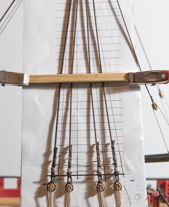
I discovered this technique somewhere on this site but I can't remember where to give proper credit for the idea.
The second thing I did was to first tie at an interval of twelve then six then three.
As we know on the real ship eye slices were used on the outer shrouds. Ed Tosti's book on Young America illustrates this well but it is difficult to do at this scale. The essence of this technique is that the line on the outer shrouds travels inward towards the middle shrouds. I simulate this by using a cow hitch on the outer shrouds and clove hitches on the inner ones. The problem with a cow hitch Both exit stands need to be held under tension. If only one is under tension the knot slips. Indeed this is the purpose of the knot as I well know from using it as a leg rope on cows art milking time. I digress. So, on can make it more stable either by following it wit a half hitch or by passing the free end back through the coils, This is what I have done here.
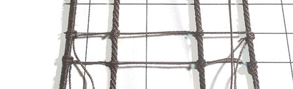
The port side is nearly complete. Only the starbord to go
John
- Tigersteve, JpR62, Chuck and 3 others
-
6
-
I agree wholeheartedly, Bob. I have worked in the chemical industry and so know a little about these chemicals. All acrylics are made small monomers which are derivatives of acrylic acid. However, as members of the general public we do not meet these because we only see the polymers (in fabrics, paints, plexiglass etc). It is generally only the workers in the industry who are exposed to these acrylate monomers. However, CA polymerises by contact with moisture in the air and the bottle actuually contains the acrylate monomer. These acrylate monomers are highly volatile, have an unpleasant odour, are lachrymatory (make us cry) and about 5 % of the population have an allergic reaction to them. Others develop an allergy after a period of exposure.
I agree avoid CA as much as possible.
John
- mtaylor, thibaultron and allanyed
-
1
-
 2
2
-
21 hours ago, Sea Hoss said:
Your coils look nice, I may use that method, thanks for the demo.
Thanks for your comment, Sea Hoss. First let me acknowledge Tom Lauria who originated this method. Tom uses an ellipse from a template such as this.
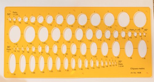
As I said I prefer a less symmetrical appearance so first I draw up a rough sketch of the size and shape I want to achieve:
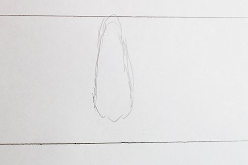
I would make two or three of these of slightly different shape since on a working ship these coils are neat but not identical.
Then i drill holes and insert pins as Tom does and continue with his method.
John
- JpR62, Ryland Craze and GrandpaPhil
-
3
-
Post 61: Faking Down
Before the ratlines get in the way I decided to at least attach some rope coils. I use the method of Tom Lauria. I find that that his oval jig produces coils that are a little too symmetrical for my taste so I slightly modify the shape of the jig to make it a little more pointed at one end. After painting with diluted acrylic medium the coils are allowed to dry and then cut from the jig.
and here are some attached to belaying pins
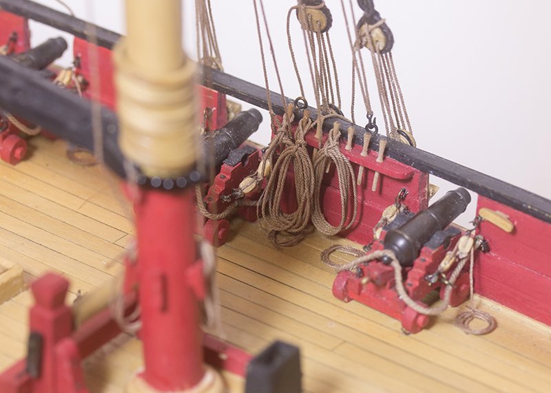
I am not entirely happy with how the look, but the more I make the better I get. The only trouble is they use up more rope than you would think and my light brown rope is fast running out!
John
- Ryland Craze, GrandpaPhil, MEDDO and 3 others
-
6
-
On 4/5/2021 at 3:49 AM, biltut said:
I just finished using some of these carving tools that I bought from Mihail three years or so ago. I had misplaced my instructions for sharpening that he supplied and found a need to contact him again for help. He provided me with a detailed e-mail regarding the sharpening process. I can only applaud again these tools as they are the best small carving tools I have found. In this correspondence, he mentioned to me that he still had three sets left for sale at $420.00. Just wanted to post this as he travels somewhere in the summer and these will not be available again until around October. If anyone is interested let me know and I will provide his e-mail as we have done in the past.
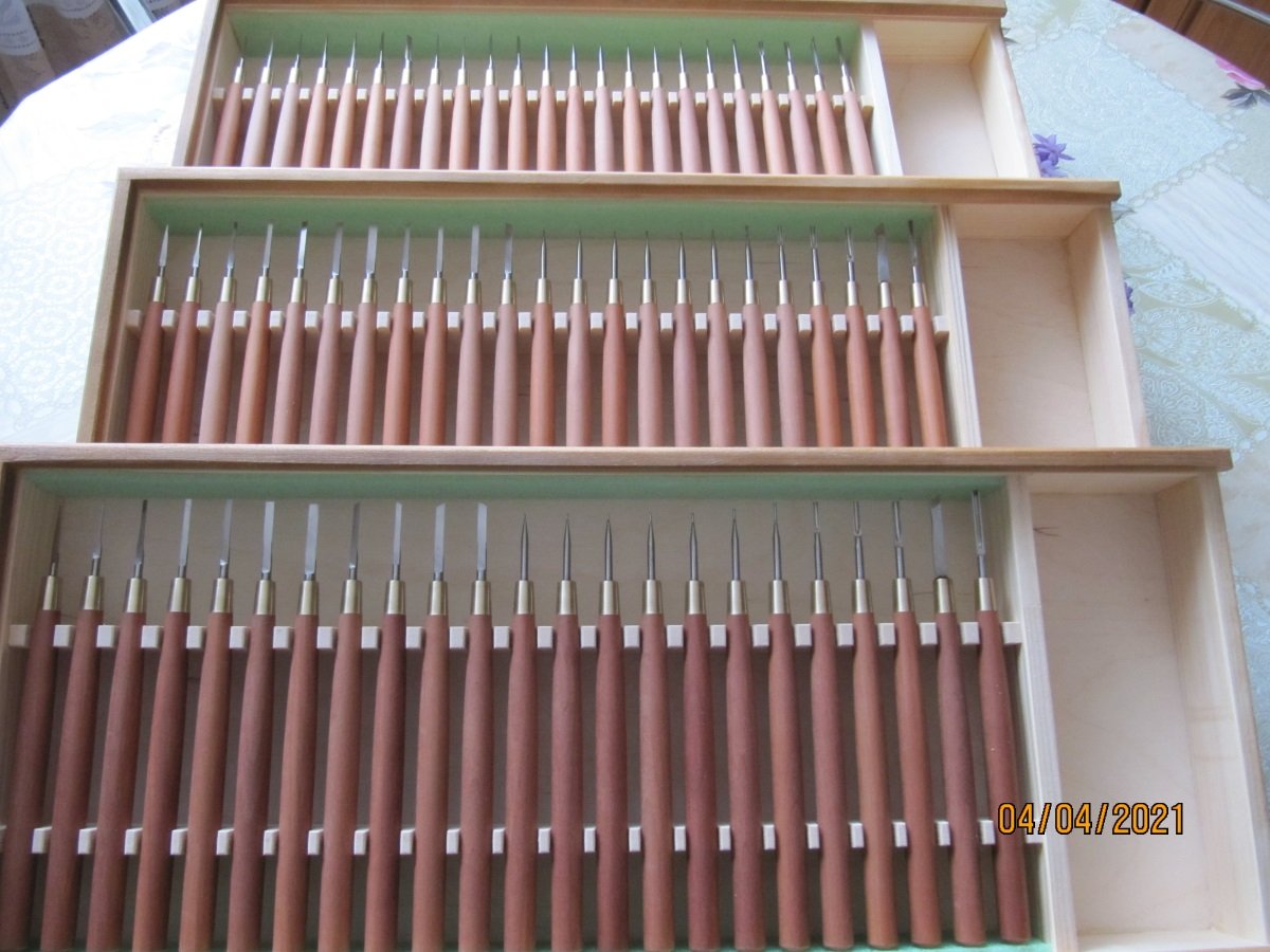
Bill Could you please provide me with Mikhail's Email address.
John
-
PRS,
The answer is yes, and no. It depends on the glue you use (PVA orCA) but in the end the bond is only as strong as the poly to wood bond. I always sand or at least roughen the poly before gluing to it.
John
-
-
On 4/28/2021 at 11:57 PM, Chuck said:
Therefore after spraying with a fixative, one can actually repaint some areas of the printout to give the feel of an original painting. Sort of like a paint by numbers after printing it. You have to do the work twice but painting over a printout that is scaled and printed to fit perfectly makes life a lot easier.....on archival paper
Another way to give a kind of 3D feel is to paint over the letters or part of them with acrylic gel medium which is available from art stores. It is transparent but builds up the surface.
John
- Keith Black, mtaylor, thibaultron and 1 other
-
4
-
By the way, I sailed for a day on the square rigger in the foreground down in Cornwall some years ago. There was no way that their deadeyes were in line. They thought it was a strange thing to expect. Apparently the shrouds stretch differently and it is more important to tension the rig to account for this than keep the deadeyes level.
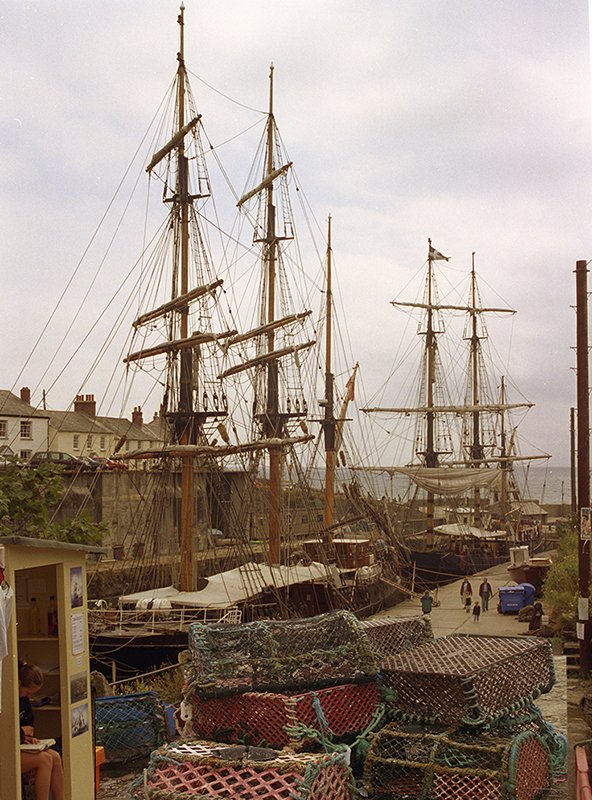
John
-
Post 60: Rigging the Shrouds
Though I have done this on my previous build, I cheated and used three horizontal seizings. This time I decided to do it the " proper" way with a throat seizing as described in Chuck's monograph. I had some discussions with him about the details of this since the book by Lees and others suggest that the shroud should run anticlockwise around the deadeye but in Chuck's diagram they are clockwise. His point was that neatness was the main point and that for a right handed person it was easier to tie the throat seizing on the right hand side and so I elected to do it that way. Incidentally, there is a detailed discussion of all this by Ed Tosti here. I also used Ed's method of keeping the deadeyes level:
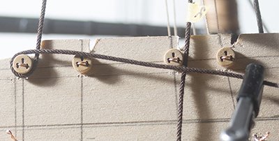
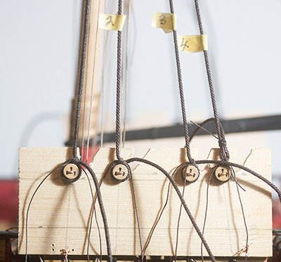
I think this is actually overkill for only four deadeyes!!
Chuck does it freehand and, it retrospect that would be just as good. In my view jigs only work if you can keep the tensions on each shroud equal. I found this easy enough for three of the stays but difficult for the fully served stay at the forward end. Anyway here is the final result,

John
- Ryland Craze, Matt D, JpR62 and 5 others
-
8

 \
\
HM Cutter Cheerful 1806 by PRS - FINISHED - Syren Ship Model Company - 1/48
in - Build logs for subjects built 1801 - 1850
Posted
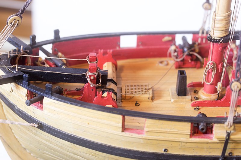
Looks great, Paul. The treenailing, the dullish red and other features make it look "authentic". some I have seen from very accomplished modelers look a bit "plastic" to my eye.
John