HOLIDAY DONATION DRIVE - SUPPORT MSW - DO YOUR PART TO KEEP THIS GREAT FORUM GOING! (Only 20 donations so far - C'mon guys!)
×


Srodbro
-
Posts
299 -
Joined
-
Last visited
Content Type
Profiles
Forums
Gallery
Events
Everything posted by Srodbro
-
One side appears vertical , and the opposite side at a slight angle: I wonder why. Would the angled side add stability while rowing and the vertical side allowed more foot room? Perhaps the angled side on the chest in front of a rower provided a better foot brace?
-
Are you planning to overlap the shields ( obscuring most of the colored strakes) or have them tangent to one another ( in which case the colored strakes will peak between them, as in the model in the pic above)?
-
Material for keel
Srodbro replied to mikegr's topic in Building, Framing, Planking and plating a ships hull and deck
Mike Bryan: I’m just curious ... perhaps I missed something. Given the plan you show, how do you go from that to drawings of the contours of the hull? -
I vote for oarsmen seated on ribs. If the relationship between the oar-ports and the ribs is correct, then the oar is level ( or close to level) with the rower’s shoulders, giving him a much more powerful, more efficient stroke. Also, the head and shoulders are better protected from wind/weather/projectiles by the height of the gunnels. I anticipate that it’s more likely that he would also have something to firmly brace his feet against, than if seated on a chest on deck. All just IMHO.
-
Outstanding work on that planking. Getting it right at the bow and stern is really challenging. Very good looking.
-
Quoddy Head Lighthouse by Srodbro - BlueJacket Shipcrafters
Srodbro replied to Srodbro's topic in Non-ship/categorised builds
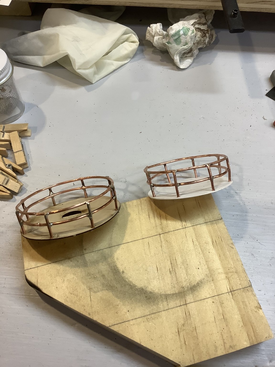
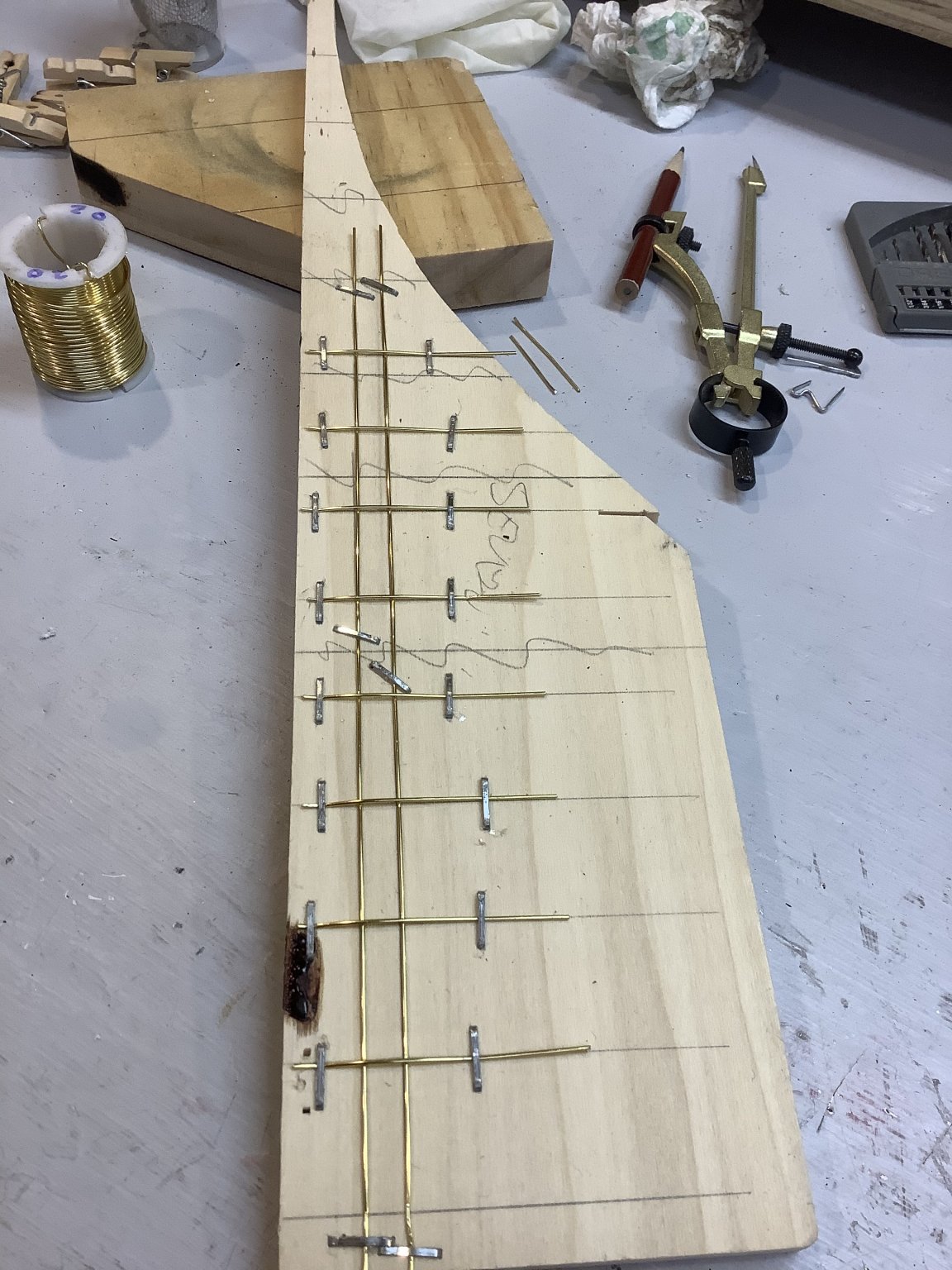
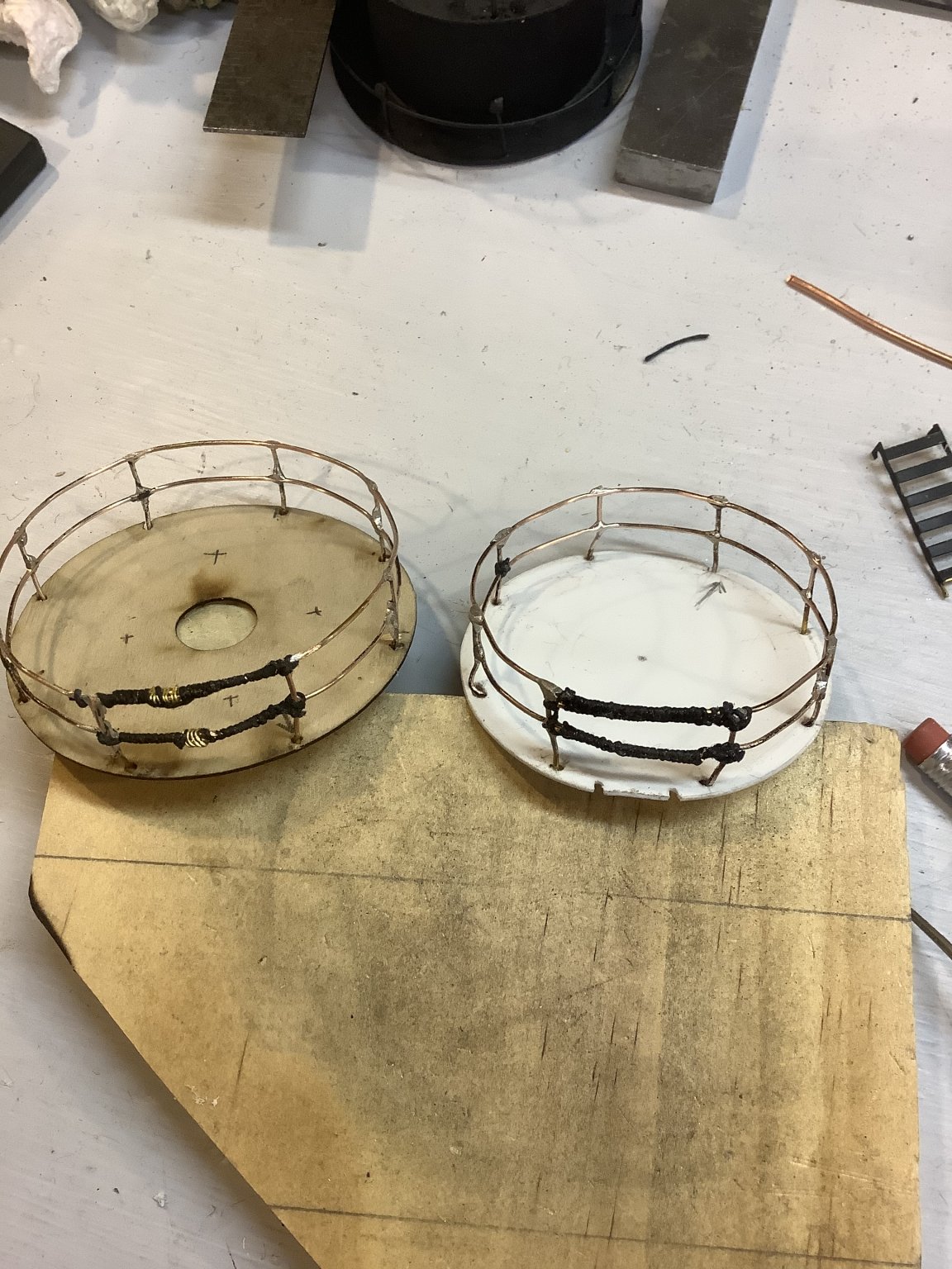
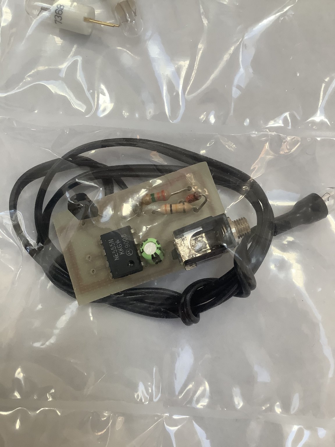
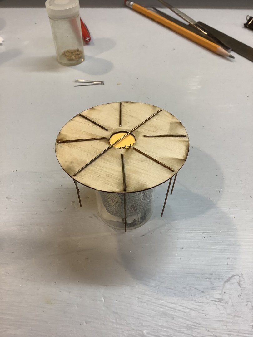
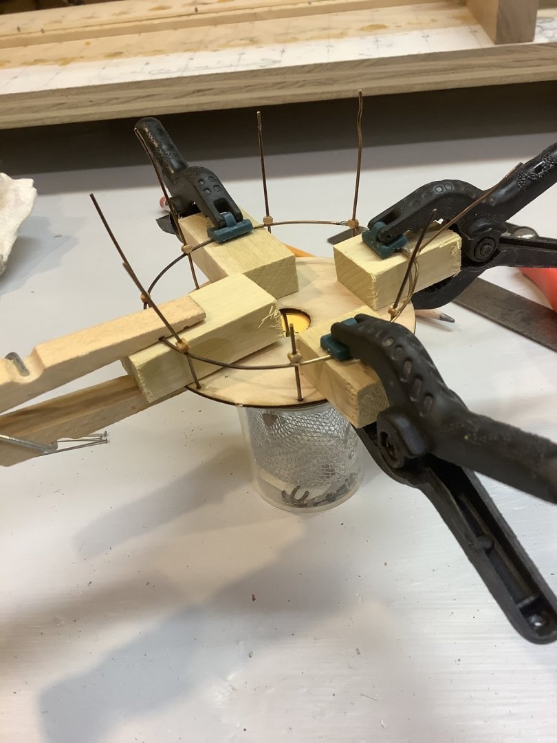
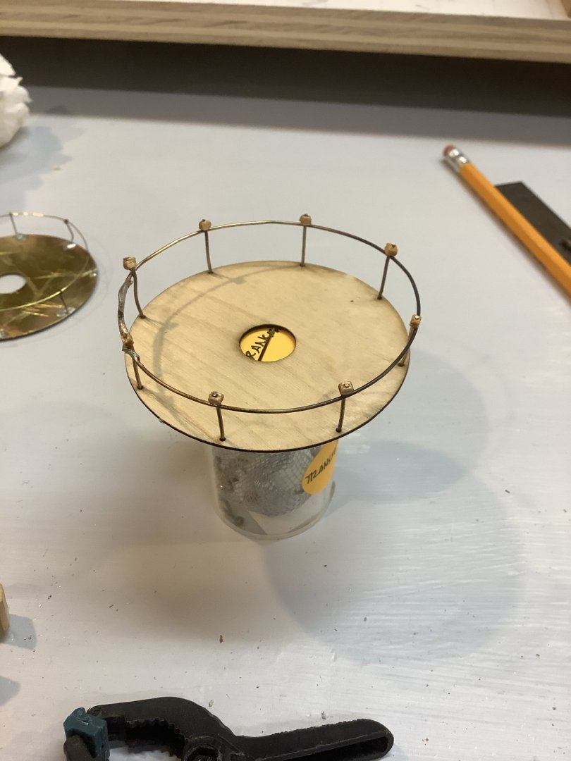
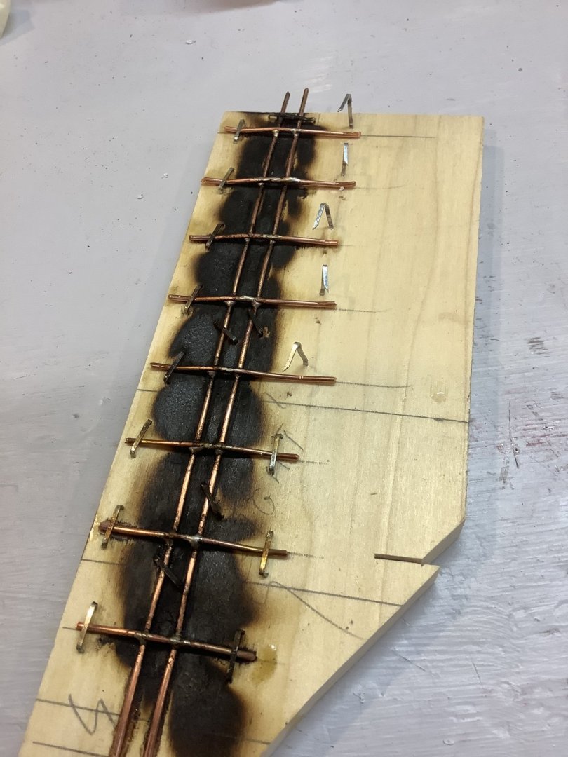
Now things are getting funky. Lesson #3: Soldering is a tricky skill. Two brass discs were furnished in the kit to serve as the deck above the lower tower, and below the light room. Several brass pins with loops, and some brass wire ( about 28 ga), were furnished to create railings around the perimeter of the two decks. Here I have soldered the stanchions to the brass deck. Clearly, I am using a torch. But, I couldn’t figure out how to solder the railing to the stanchions. Also, I thought that In soldering these pieces together the heat would compromise the already soldered joints at the deck. Also, I thought the railing wire was far too whimpy, maybe scaling to only about 1” diameter, which I thought was too small. I decided to try something else that didn’t involve soldering. I’d wasted a brass disc, but fortunately found included in the kit a pair of wooden discs. I formed new stanchions out of 24 ga brass wire, and extended the portion under the deck to give a larger surface area to attach them to the wooden deck with CA. On the top side of the deck, I used spacers to help in clamping the railing to the stanchions. Figuring that a CA joint between the rail and stanchion wire wouldn’t hold up, I formed a ball joint from small wooden blocks to provide more glue surface. I figured I could file these down to look acceptable. Nah! I didn’t like that how that turned out, either. Maybe I’ll go back to soldering. Lesson #4: Soldering is REALLY tricky, requiring skills I don’t have ( yet). I thought the problem with soldering was being able to hold onto several pieces at once while also holding the solder and torch. This can’t require two people to do. So, I created a jig to hold the stanchions and rails ( I had discovered from photos that there are actually two rails at each level) in position while soldering. I had to determine the developed length of the deck perimeter and the spacing of the stanchions, then stapled the pieces to a board. I also used 18 ga copper wire, something I thought would be more robust. Shaped and cleaned up, it wasn’t too bad. But, the more robust copper wire looked just too thick, scaling to about 4” diameter, much too big. So, now that I thought I had a soldering technique, I’d try again with 20 ga brass wire. This really didn’t work as planned either ... I couldn’t figure out how to join the ends of the railings so I wrapped them in thread to simulate seizing. Also, I miscalculated the spacing of the stanchions on the upper deck, and ultimately had to cut another upper deck from pvc since I’d wasted the brass and wooden ones from the kit. But, the diameter of the stanchions and railings were finally right. But, I had had enough. This was going to have to do. Maybe a good coat of black paint would hide some of my sins. More to come.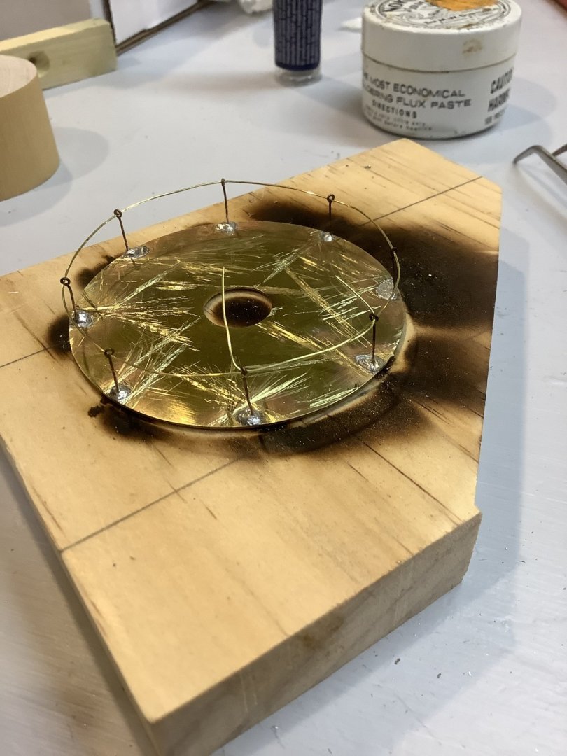


-
Quoddy Head Lighthouse by Srodbro - BlueJacket Shipcrafters
Srodbro replied to Srodbro's topic in Non-ship/categorised builds
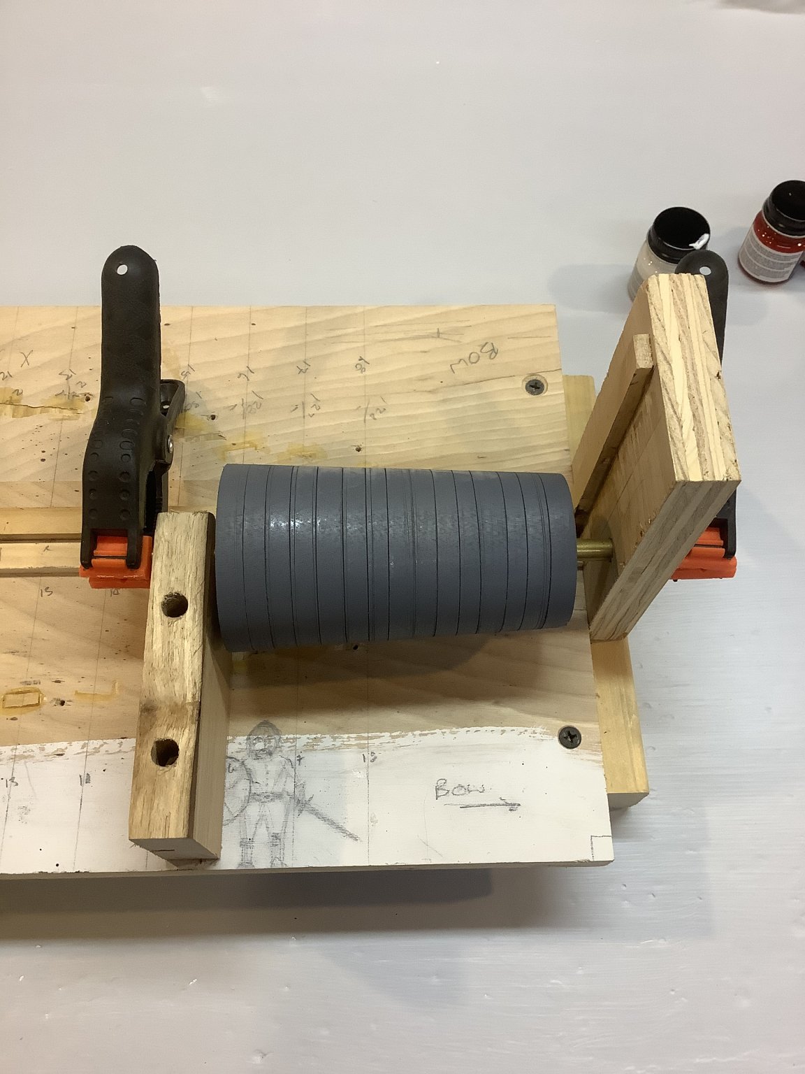
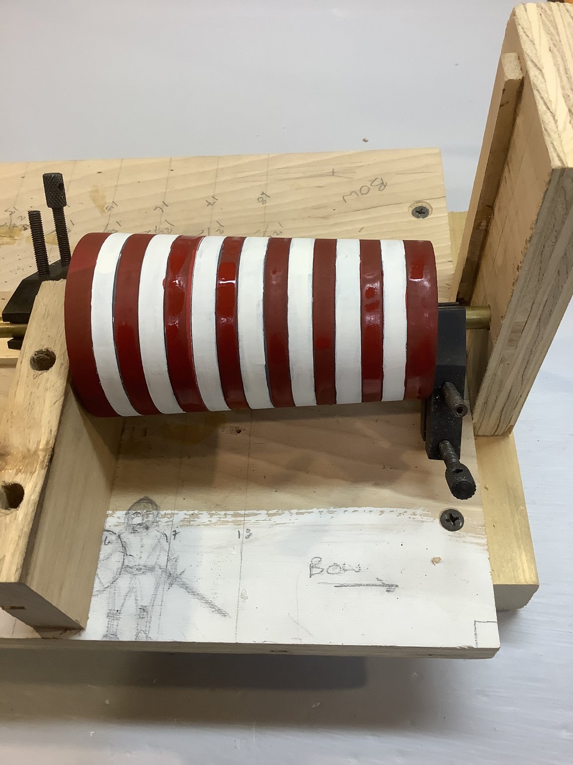
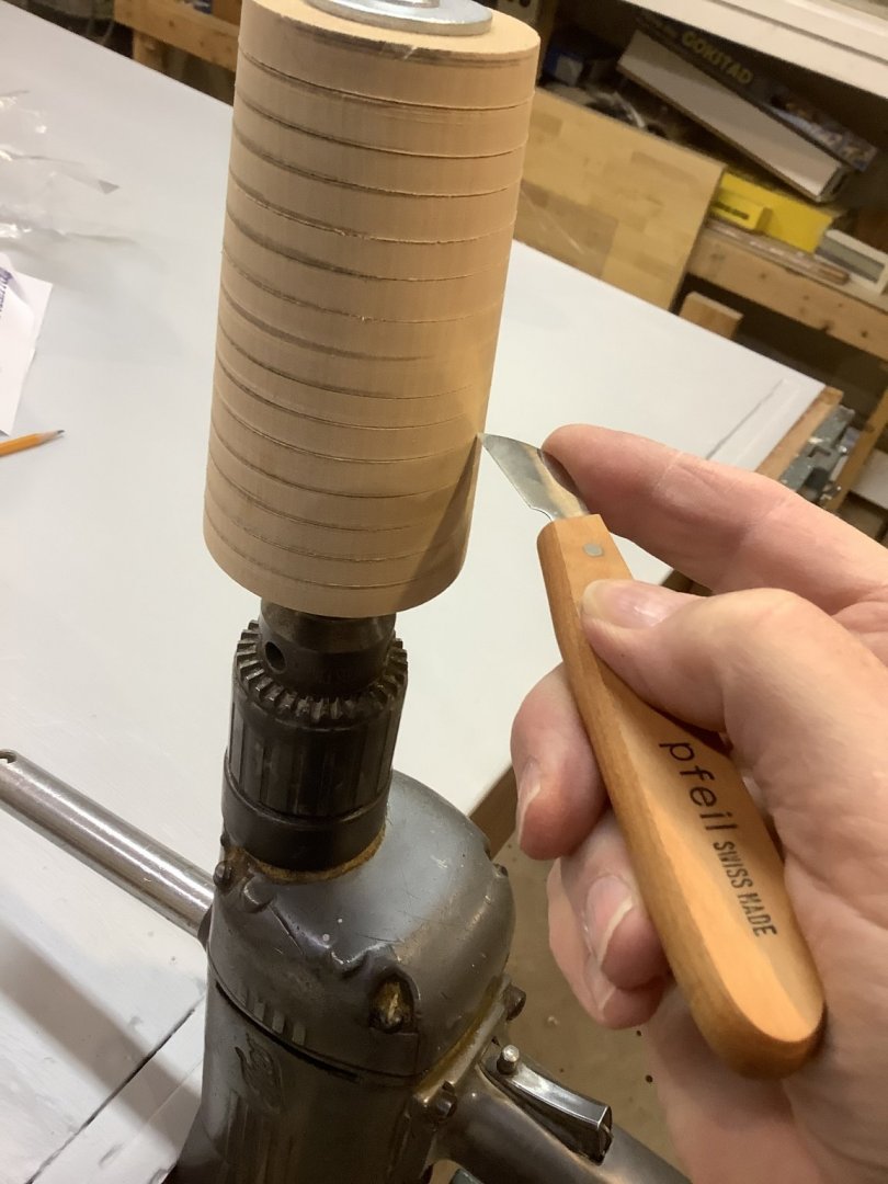
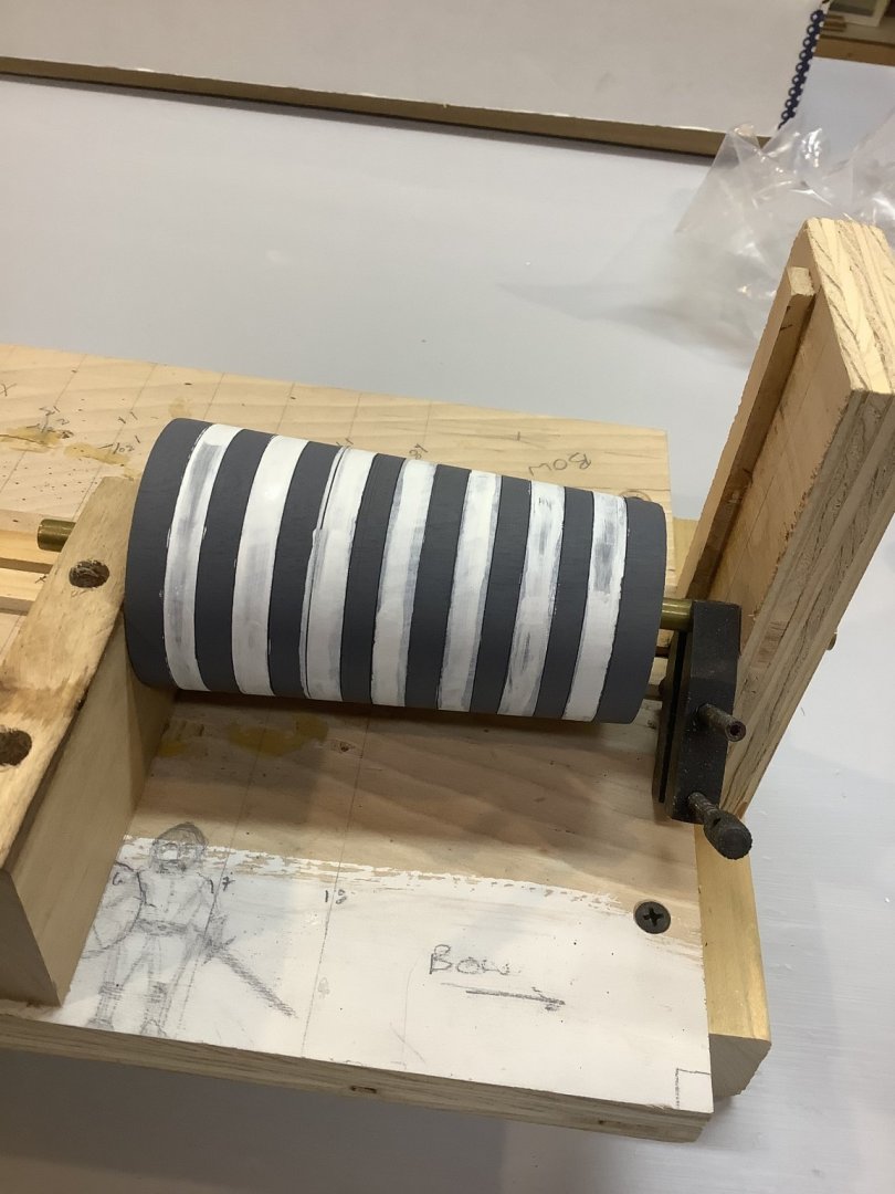
I debated with myself about completing this build log and procrastinated long enough that I came to the conclusion that I owed it to those who follow and who have shown enough interest to comment that I need to complete a build log for this. I spend a lot of time looking at other’s logs, and am disappointed when they just die without finishing. I learn so much from others. So, there seems a bit of obligation outstanding on my part. So, on the theory that we learn from mistakes, and might also learn vicariously from the mistakes of others, I offer the following log of mistakes and disappointments ( but, take heart ... ultimately there is a happy ending). Lesson #1: Big Things (big challenges) Come in Small Packages. I was very pleased with my two previous builds (semi-scratch USBrig Lawrence, aka Modelexpo Niagara [another build the log of which I must complete] and Dusek Gokstad ship). I thought I could have a pleasant little diversion with the lighthouse kit. Keep in mind that this “kit” was assembled for me at my request by the good folks at BlueJacket models from spare bits and pieces they had of a defunct kit they used to offer. So, any short-comings cannot be assigned to the manufacturer ... all the mistakes and frustration were of my own doing. The kit consisted of a wooden dowel, tapered, for the lower tower, a short wooden dowel for the upper tower, a cast metal roof, and laser etched brass for the light enclosure and vestibule building, and a couple of brass disks for the upper and lower decks. There was also a bit of electronics to activate the light (ultimately not used as I couldn’t figure out how to power it, and my decisions during construction eliminated the means of installing this feature). Simple, eh? Stay tuned. Instarted with the lower tower dowel which was already tapered and sanded. I wanted to add a bit of texture to better represent the brickwork, so locked it into a drill, roughed the surface a bit with coarse sandpaper, and cut a few brick courses into it to better define the stripes. Lesson #2 - Painting stripes is not easy. The kit included some red tape to be used for stripes. But, the width of the tape would have resulted in either non-uniform red-white stripes, or the wrong number of stripes. Also, because of the taper to the tower, getting the tape to conform was messy. In order to paint the alternating red and white candy stripes fairly uniformly, I found I couldn’t just utilize the drill rig . it spins too fast and had a slight wobble. I had to repurpose a jig from another build to hold the tapered base on an axle to evenly spin the dowel while holding a saturated paint brush. More to come.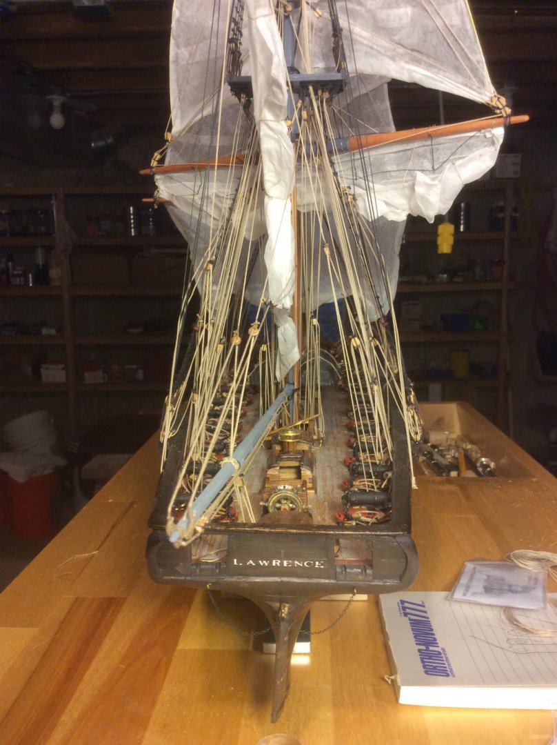


-
How did you hold the garboard plank in position when you glued it to the keelson?
- 63 replies
-
- 1
-

-
- bluejacket shipcrafters
- new bedford whaleboat
- (and 1 more)
-
Just a suggestion: I found the jig in this build log listed below very useful. Even using the jig, with the keel and frames quite plumb and square, aligning some of the planks from one frame to another was a challenge. Nice color choice. Gokstad Viking Ship by jack.aubrey - Dusek Ship Kits - 1:35 Scale
-
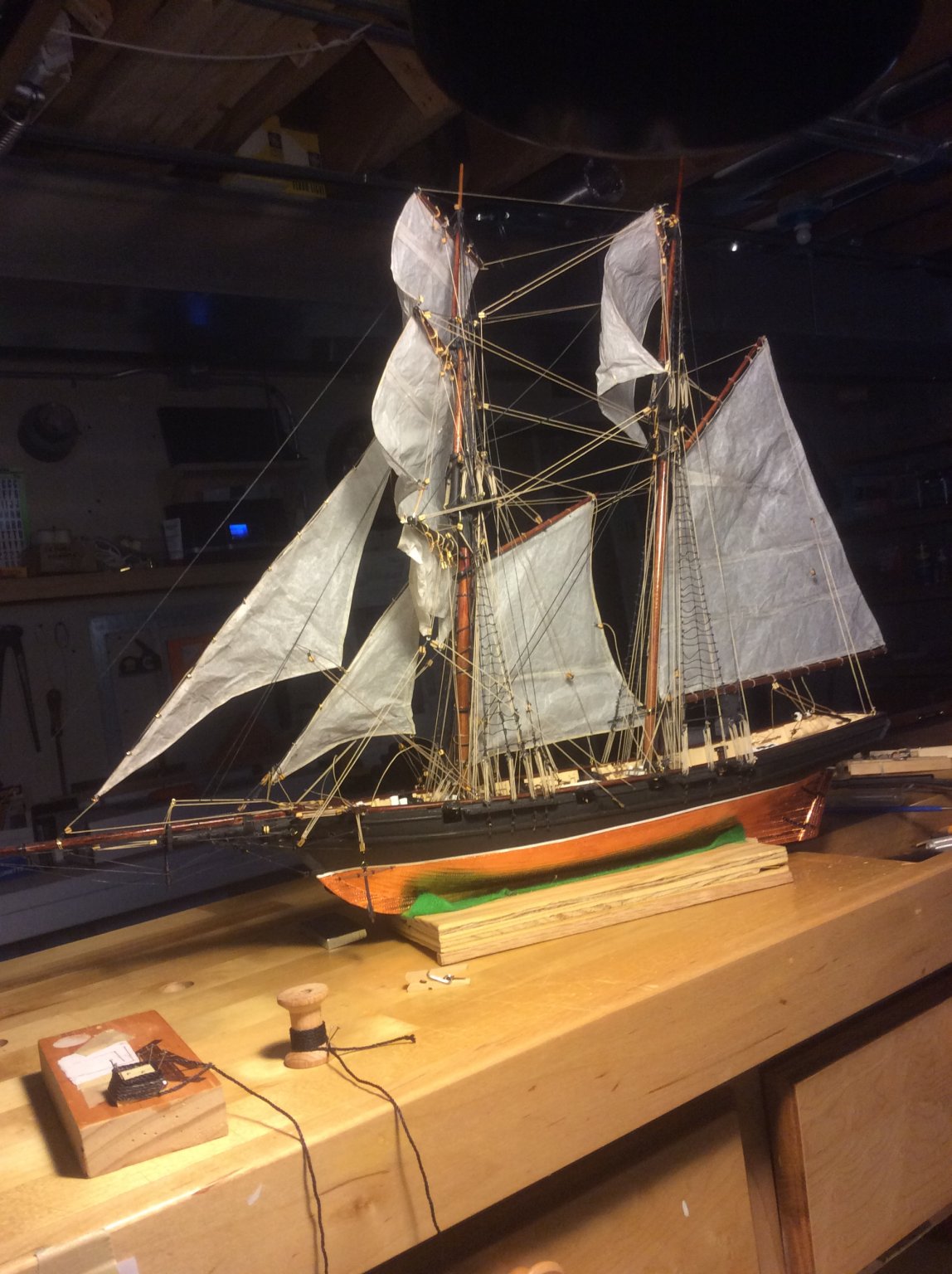
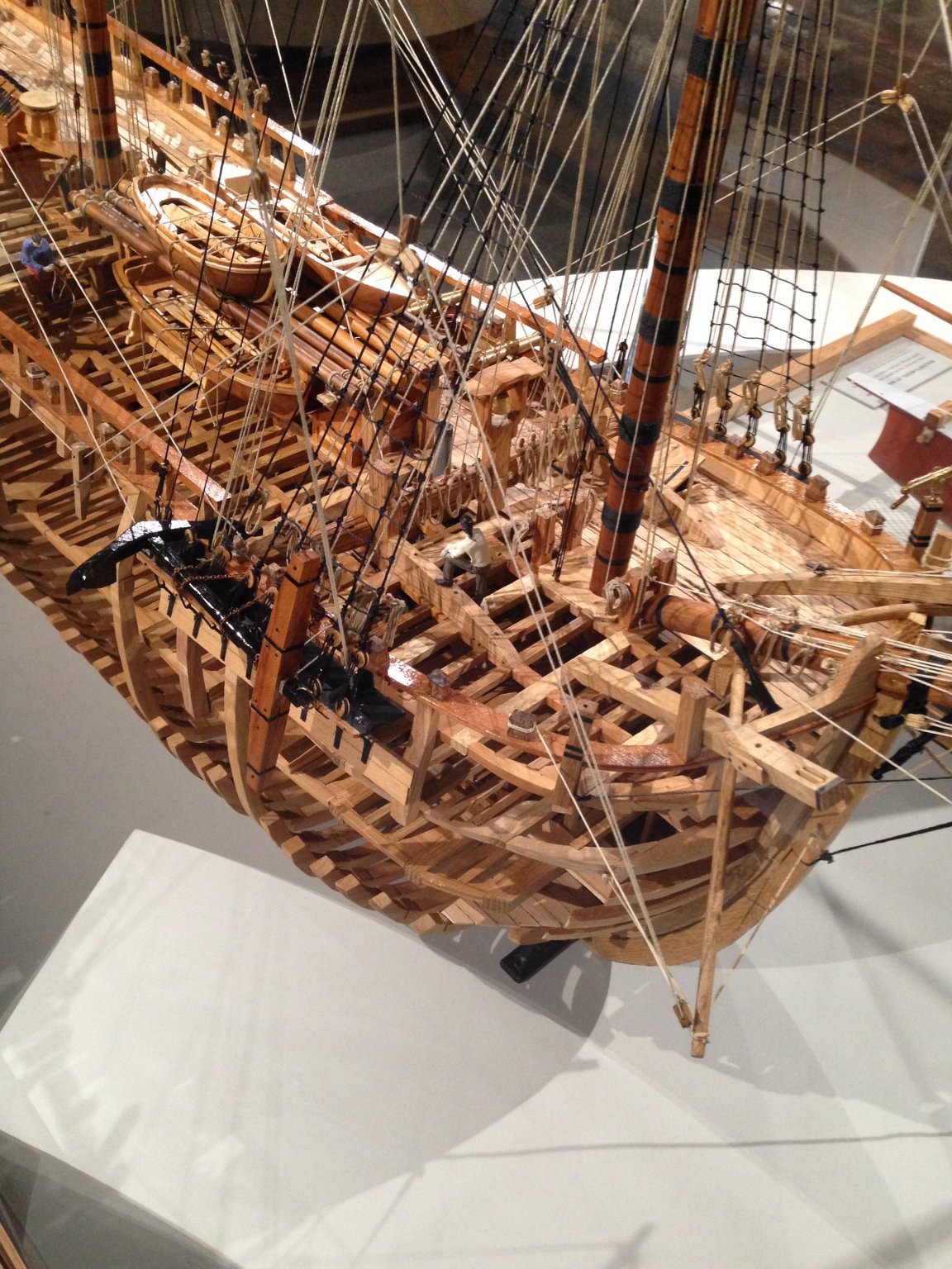
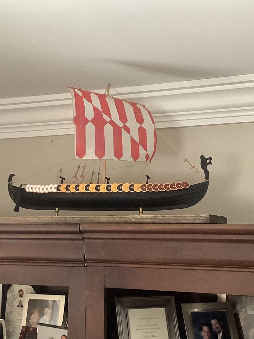
I love that kit! So glad to see a couple people are building it. It has been around awhile, and the thing I like about it is, since Dapper Tom was not a real ship, a modeler can do whatever he wants to the details, and nobody can say it’s wrong! I got mine as a partial complete build on eBay ( the hull had been sanded) and loved building her ( I re-christened her Quoddy Bay, after the bay we have a house on in Maine, to commemorate the privateers/ pirates who sailed there) I like that kit so much , I got another partial build on eBay, and one more on sale from Modelexpo). The first kit I got was about thirty years old, and the instructions were on one page. Required a lot of interpretation. Here she is, just before completion. Will be following your log with great interest. Have fun.

-
Very nice work.
-
Just a quick follow-up: I found this reference invaluable for understanding the construction of the ship. It is the original 1882 Norwegian narrative describing the archeological discovery. Text is in both Norwegian and English. (Found it as one of the “further reading “ references in Wikipedia article on this ship, in case the link below doesn’t work). http://resolver.sub.uni-goettingen.de/purl?PPN561535841
-
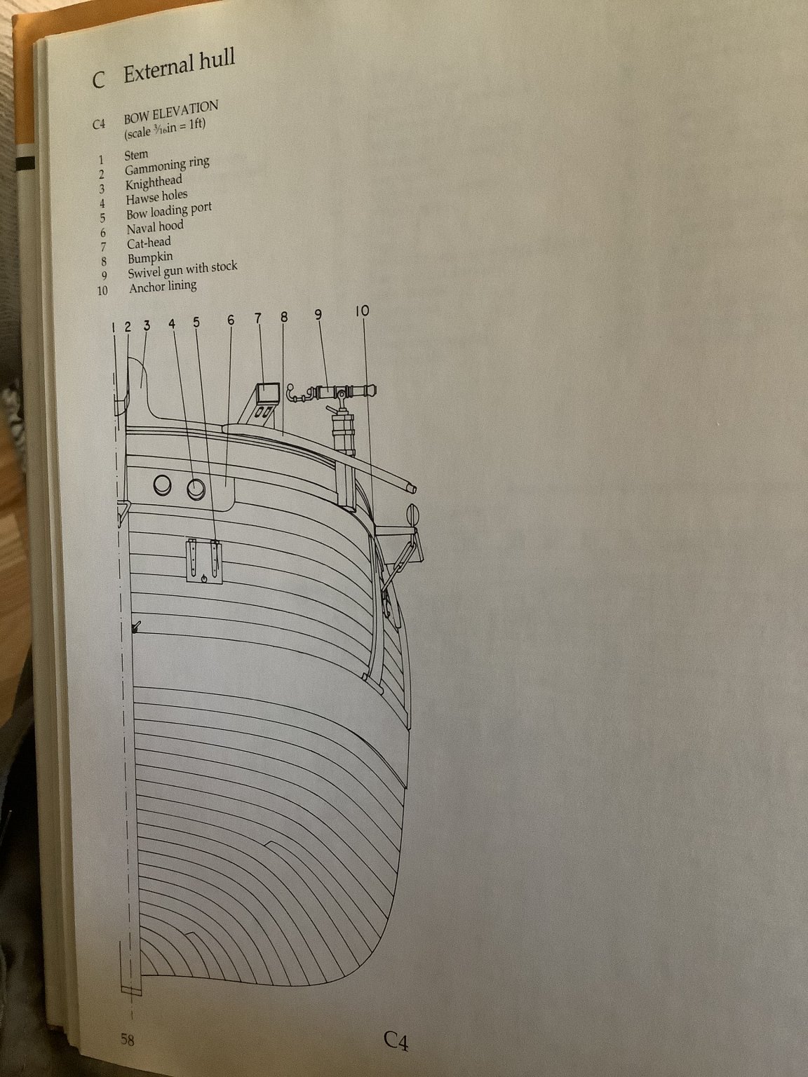
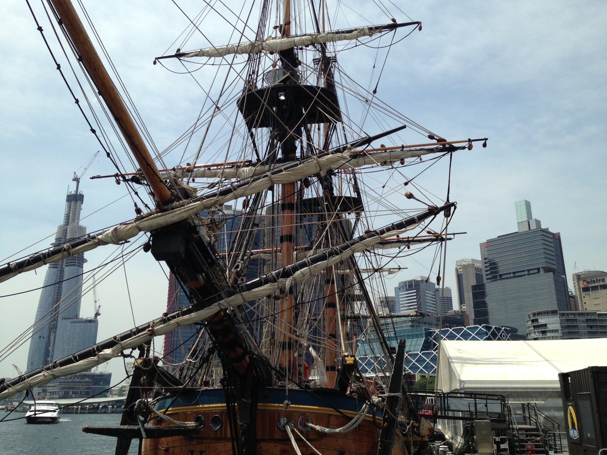
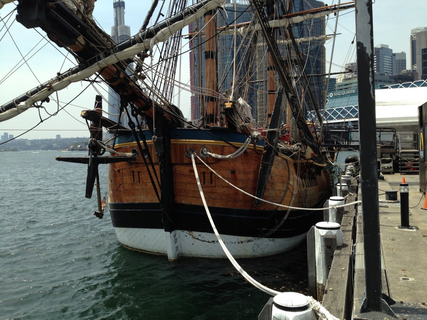
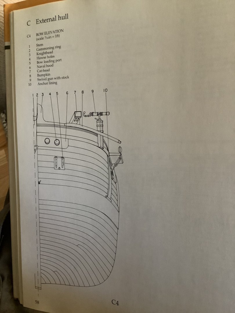
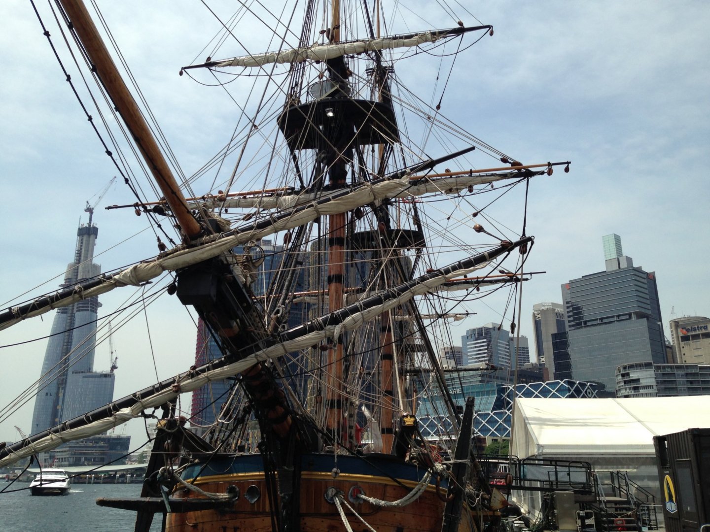
Love your build. Endeavor has been on my bucket list for a long time. I was fortunate to be in Sydney just before the whole COVID-19 thing started, and was able to see the Endeavor replica there. I took this pic, which shows the planking at the bow. Below the wales, the curvature of the planks differs significantly from that shown in the Marquardt AOTS Endeavor book: I was wondering how the kit plans show this. Also, if you look closely at the photo I took, several planks in the white area, as they curve upward, just before entering the black area, that seem to terminate with an odd “hook” shape. I wonder if this is to facilitate attachment to the timbers behind, which are oriented horizontally, rather than vertically as most of the frames are. Looking forward to more of your build.
-
Ah-ha! Great. I recently finished mine, and will be following closely. I take a lot of “artistic license” liberties with my builds. I thought Dusek made a pretty good kit.

-
Quoddy Head Lighthouse by Srodbro - BlueJacket Shipcrafters
Srodbro replied to Srodbro's topic in Non-ship/categorised builds
Yeah, thanks mtaylor. Tried that search without success. I’ll probably start a build log on this lighthouse project. .... is this the right place for it? -
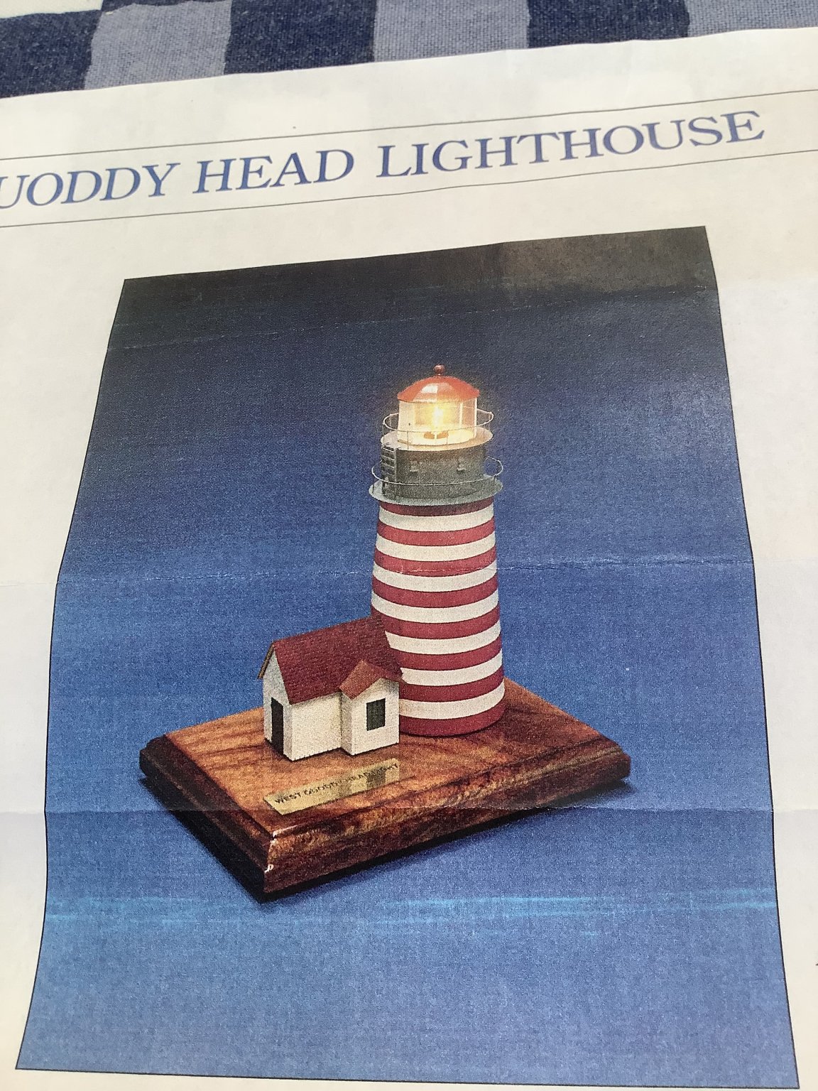
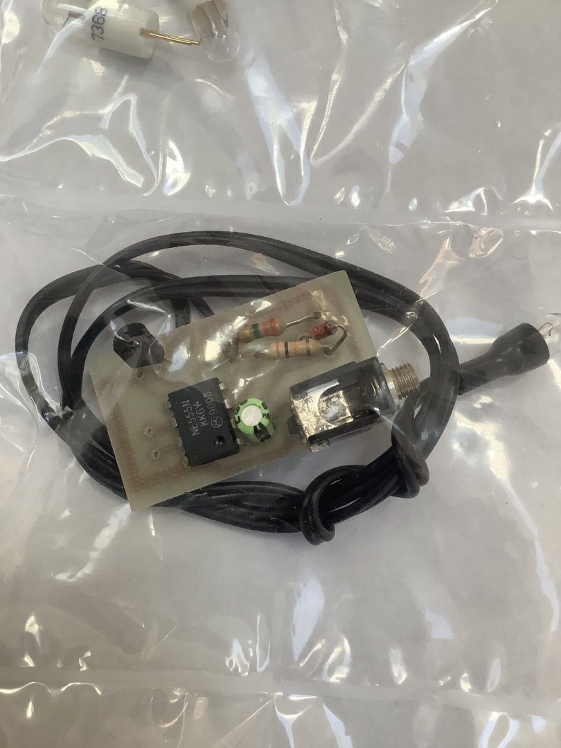
Not sure if I’m posting in the right place, but if moderator wants it elsewhere, please move it. Close to two years ago, I purchased from Blue Jacket their West Quoddy Head Lighthouse Kit. At that time it had been discontinued for several years, but I persuaded the good folks there to cobble together a kit from whatever parts they had available. I’m finally getting around to starting the project. Around the time I purchased the kit, I was able to find on these forums a build log that someone wrote on this kit. It had details about the electronic flashing light accessory. Unfortunately, the components I received from Blue Jacket have no instructions for this accessory. I am wondering if anyone out there might know of the log I am searching for (I’ve done several searches of the forums without success) and can give guidance. Thanks.

-
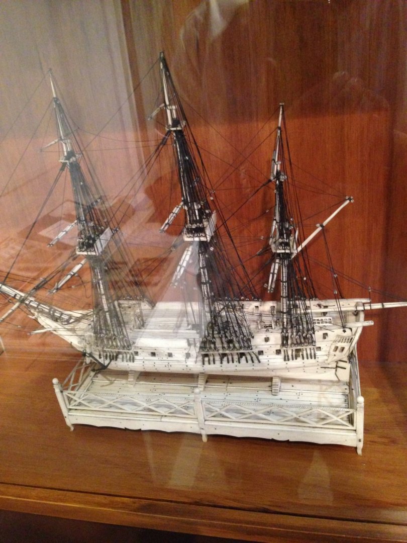
Welcome. Wife and I were in your town about three weeks ago. Was impressed by the models at the Maritime Museum ... great stuff.

-
I was fortunate to be in Sydney, Australia last week and briefly visited HMS Endeavor. I was surprised to see that the sails were not attached to the jackstays but lashed to the yards. Or am I mistaken that the “rod” above the yard isn’t a jackstay?
-
Thanks, all, for responding.
-
Looking good. Glad to see progress.
-
Hello, Ensign I know this follow up message is very late from your post ... Did you ever succeed in finding a satisfactory rigging plan? If so, what was it? I am considering a scratch build of Endeavor, and am gradually trying to assemble information, plans, etc. In a couple weeks I’ll be on a cruise to New Zealand and Australia, and hope to get to Endeavor in Sydney, and see if the Maritime Museum might have anything useful for a modeler. Thanks.
-
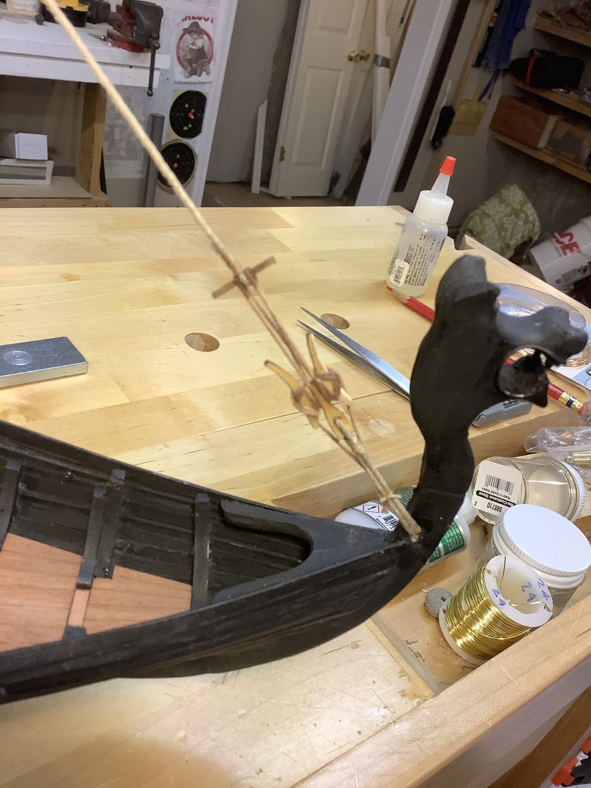
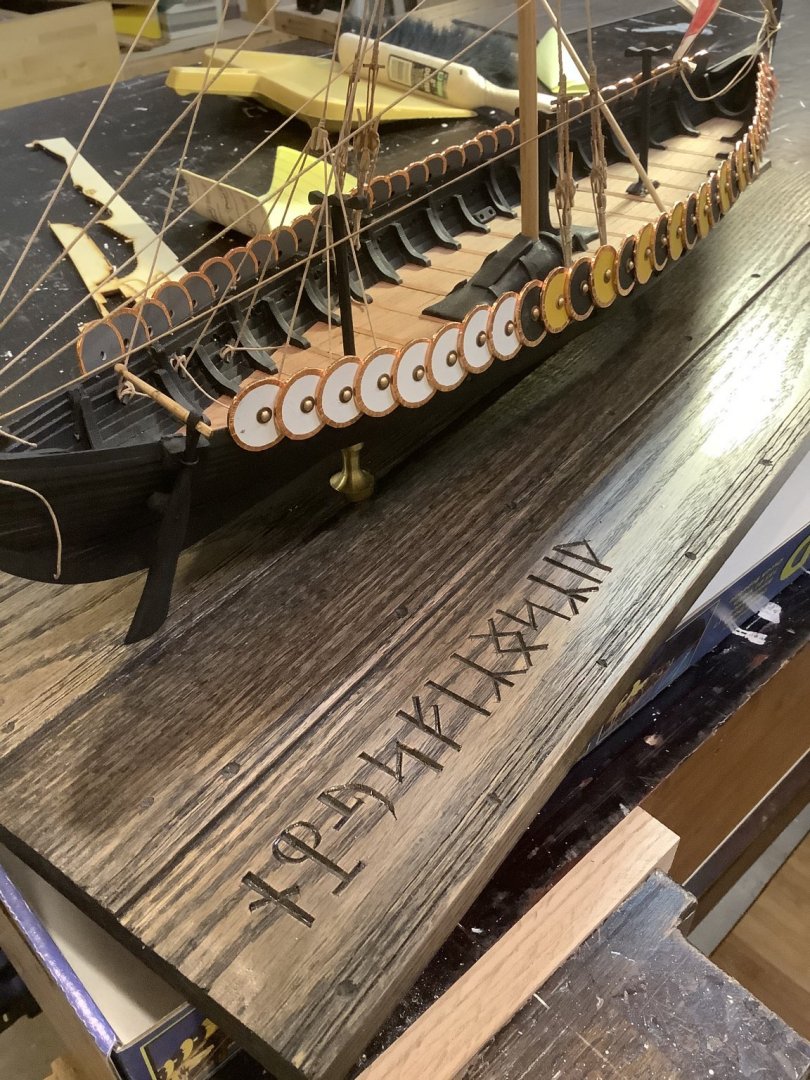
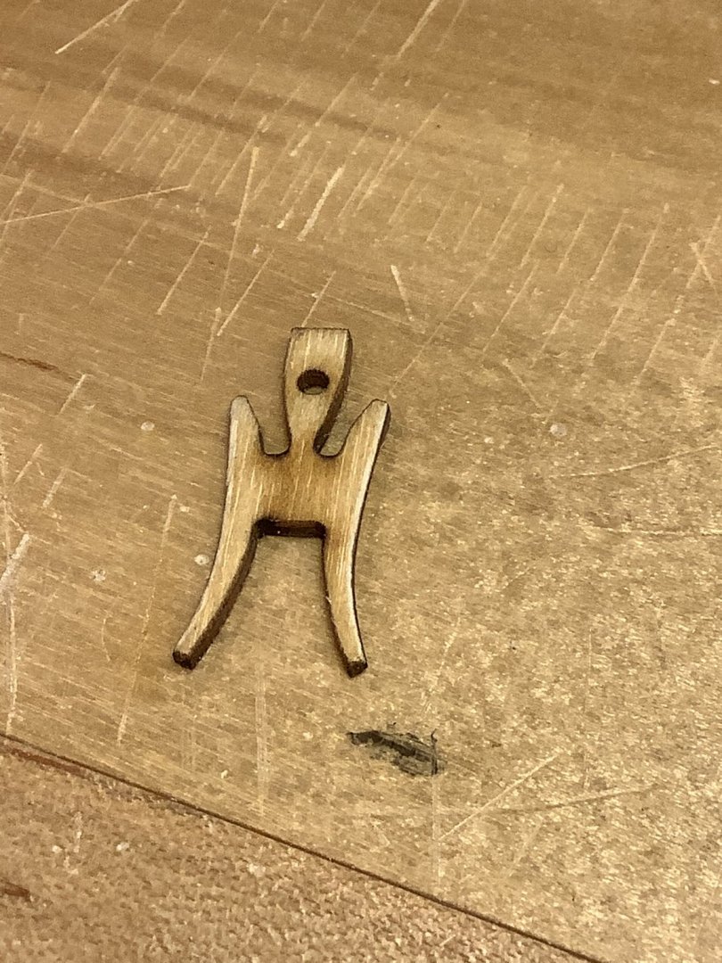
I am currently building the Gokstad Ship by Dusek. Integral to the rigging of the shrouds and stay is this “ thing”, to facilitate frequent raising or lowering of the mast. The kit variously refers to it as a shroud block, or shroud cleat, in spite of the fact that it also occurs in the stay. N.Nicolaysen’s beautiful treatise from 1882 on the Gokstad Ship Discovery has a great sketch of it, but does not name it other than “ unidentified implements “. I’m sure 9th or 10th Century Scandinavian sailors had a colorful or functional name for it, probably referring to some animal name, or something to do with a sexual reference ( or maybe both) as sailors are wont to do. In this pic I’ve installed it in the stay. Any suggestions?

-
Just found your build log on the way to looking for something else. I’m currently cobbling together the Gokstad Ship kit and can appreciate some of the challenges you’ve faced. Will be following your further work ... which is great. Also, big thanks to Louie-da-fly ( and others, as well) for the links he provided on the construction of these viking craft. Great stuff.