HOLIDAY DONATION DRIVE - SUPPORT MSW - DO YOUR PART TO KEEP THIS GREAT FORUM GOING! (Only 51 donations so far out of 49,000 members - C'mon guys!)
×


FriedClams
-
Posts
1,368 -
Joined
-
Last visited
Content Type
Profiles
Forums
Gallery
Events
Everything posted by FriedClams
-
 Great execution of details FF - they look terrific. Thanks for the info on the fly-tying thread, ultra fine thread is always good to have on hand. Gary
 -
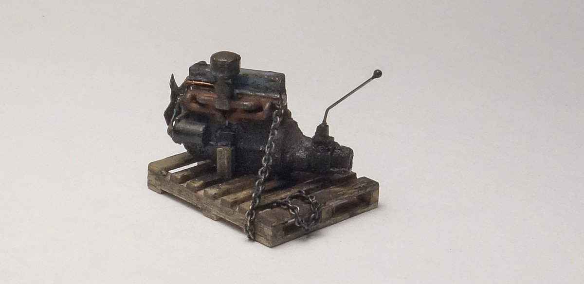
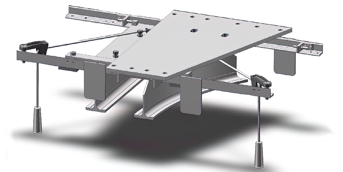
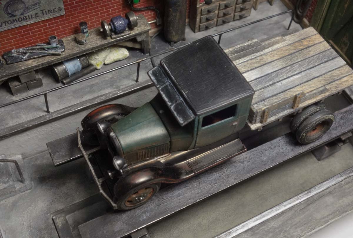
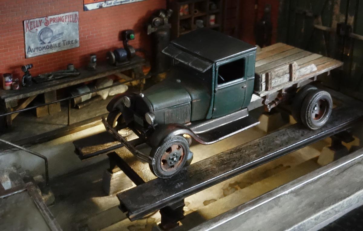
I worked in manufacturing most of my life and the millwright/welding shop at one location had a rather extensive trolley system that could deliver large sheets of stainless and other heavy stock to any of the fabrication benches. This system used several glide switches and I'm sure it prevented unnecessary worker injury by reducing manual handling of the stock. Thanks Egilman for the nice words. No, it is I who thank you and all the members for receiving this build with interest and such kindness. I've learned so much from the members here at MSW, the insights, expertise and suggestions, that I'm happy to be able to offer something (as humble as it is) in return for all that I have gained. I lurk around at other modeling forums from time to time but have never posted because frankly, it is just too time consuming and I can't keep up with all the great builds going on here, never mind other forums. Thanks for following and your nice comments OC. That “Train your wife” poster was written by a man who has never been married, doesn't know anyone who has ever been married and probably has never even had a girlfriend. But it did make me chuckle and no I won't be including it. Thanks Lou. Ha! Perfectly stated Keith. Yes Roger, I remember the coveted Rigid calendars “back in the day”. Rigid owned the pipe threading market and in the electrical trades Greenlee ruled in mechanical and hydraulic benders. Every year our shop received a new calendar from our suppliers and for several weeks guys would filter in off the production floor just to check it out. Beautiful young women in bathing suits. Thank you Mark, Keith and Egilman for your fine comments and suggestions. In the back of my head, the tranny did bother me and your collective recommendations gave me the push I needed – so thanks! I found this image on-line of a 42 Chevy pick-up which had a 216 inline and original transmission. I needed to see what the shift lever looked like. So I sanded a flat on the top of the tranny, added some styrene bits and the shifter which is made from .010” phosphor/bronze. I also added a clutch throwout lever sticking from the bell housing, but with all that darn grease and oil sleaze it is barely visible in these photos. I'm happy with the way it turned out. Thanks again. And thanks to all for the likes and for looking in. Gary
- 189 replies
-
- 19
-

-

-
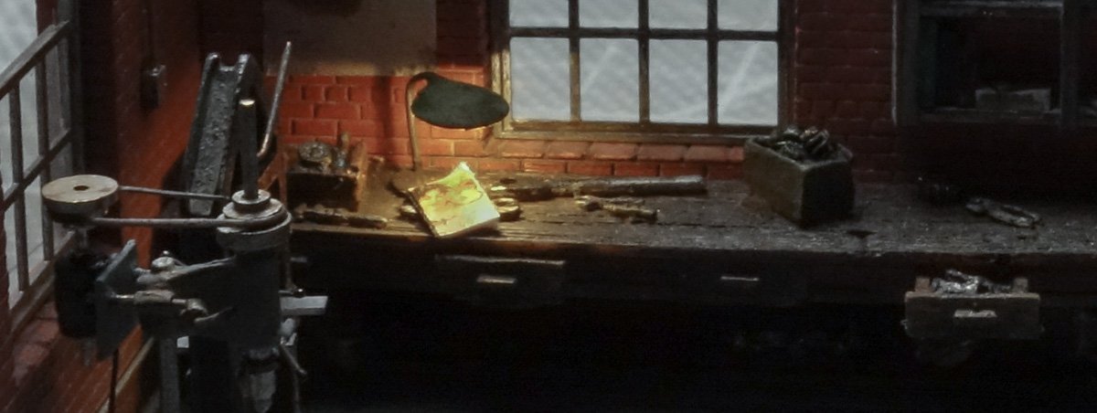
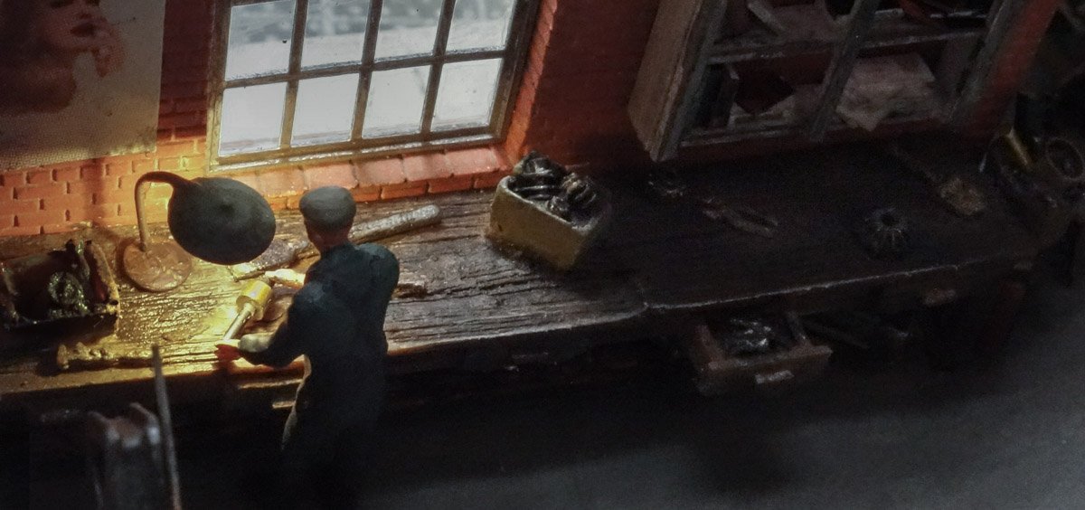
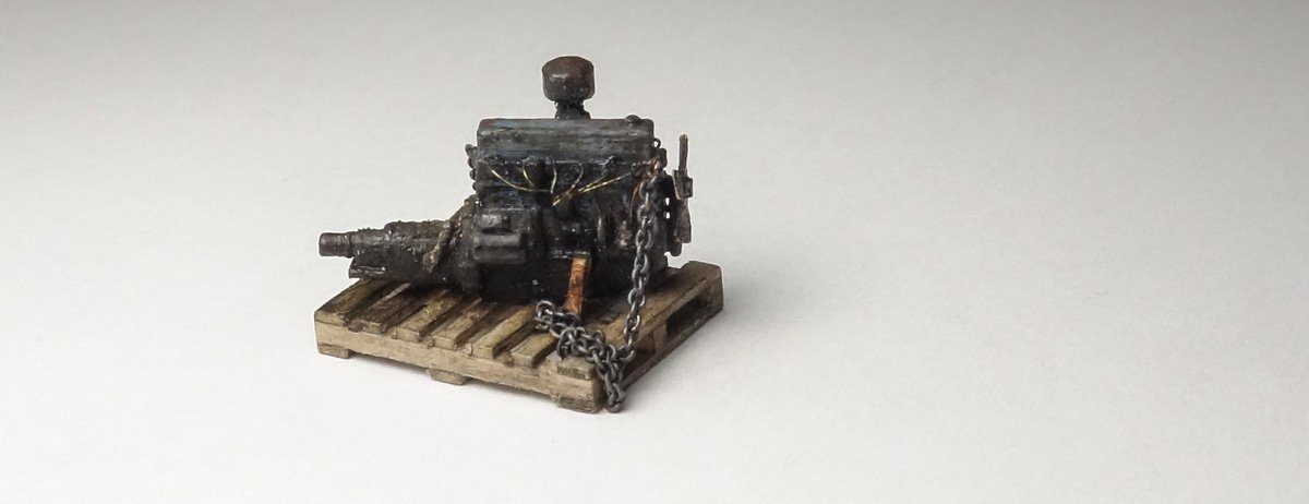
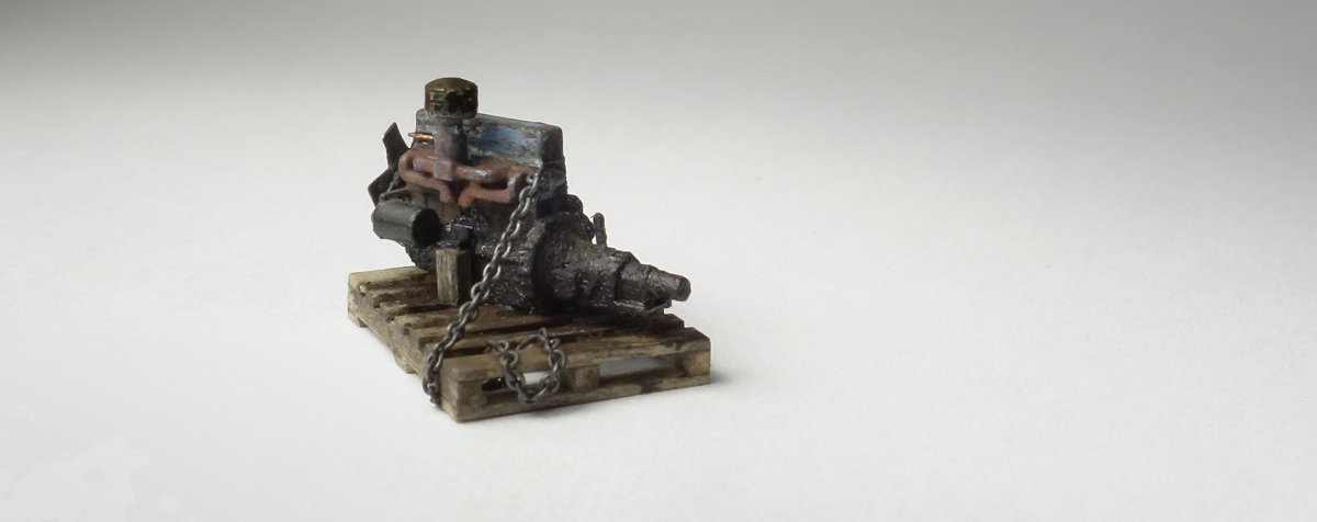
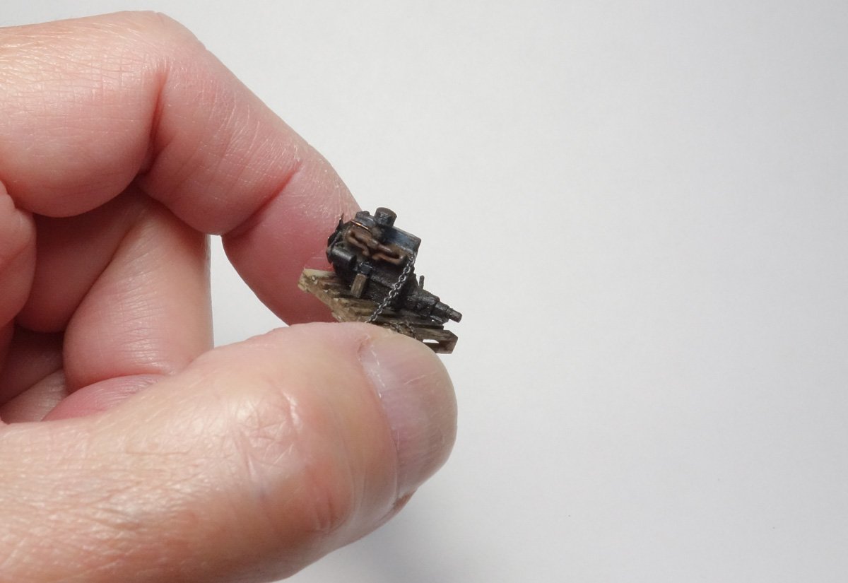
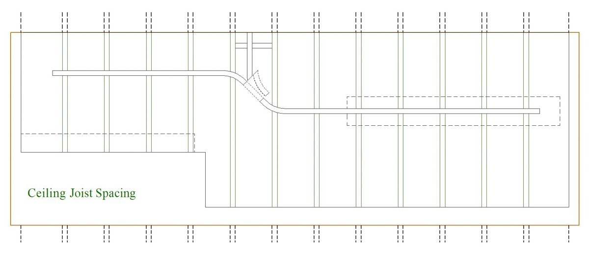
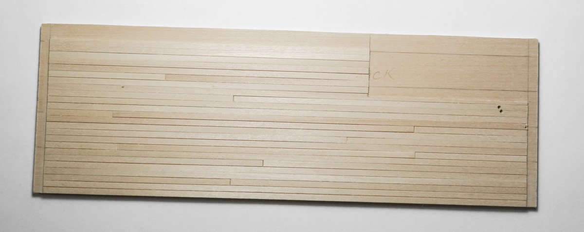
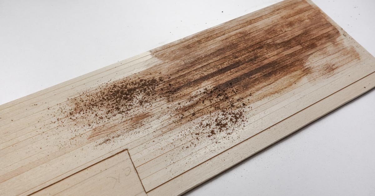
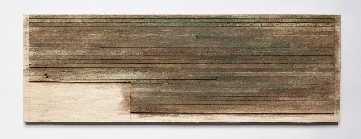
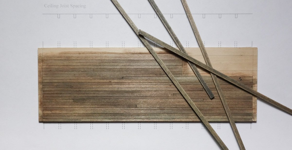
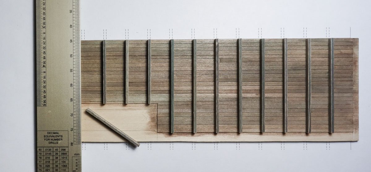
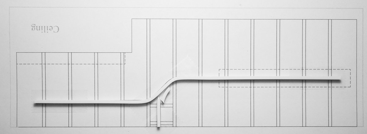
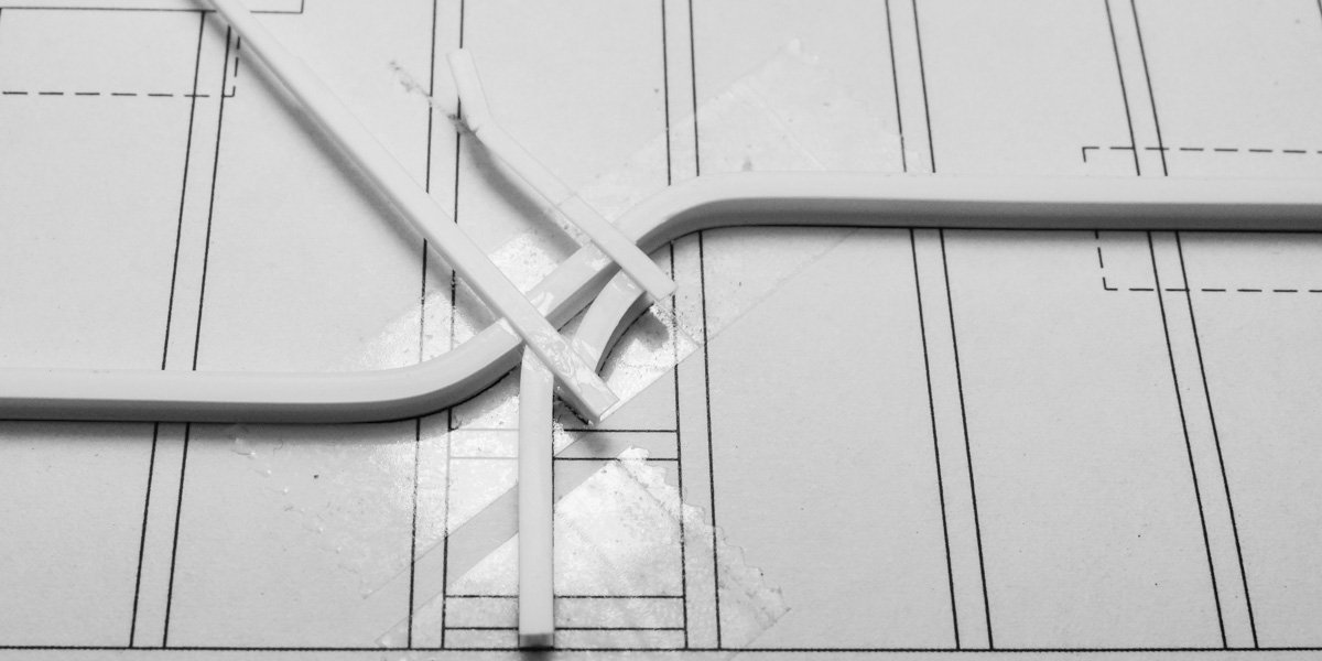
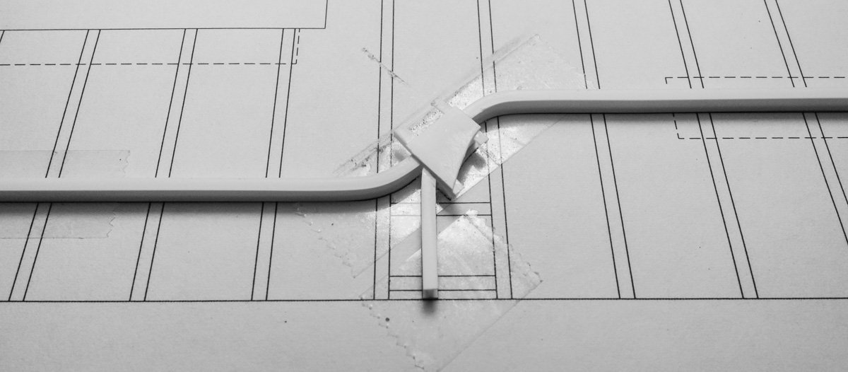
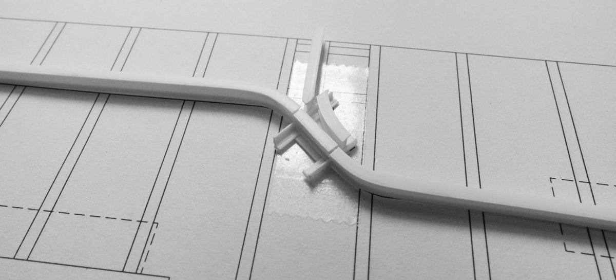
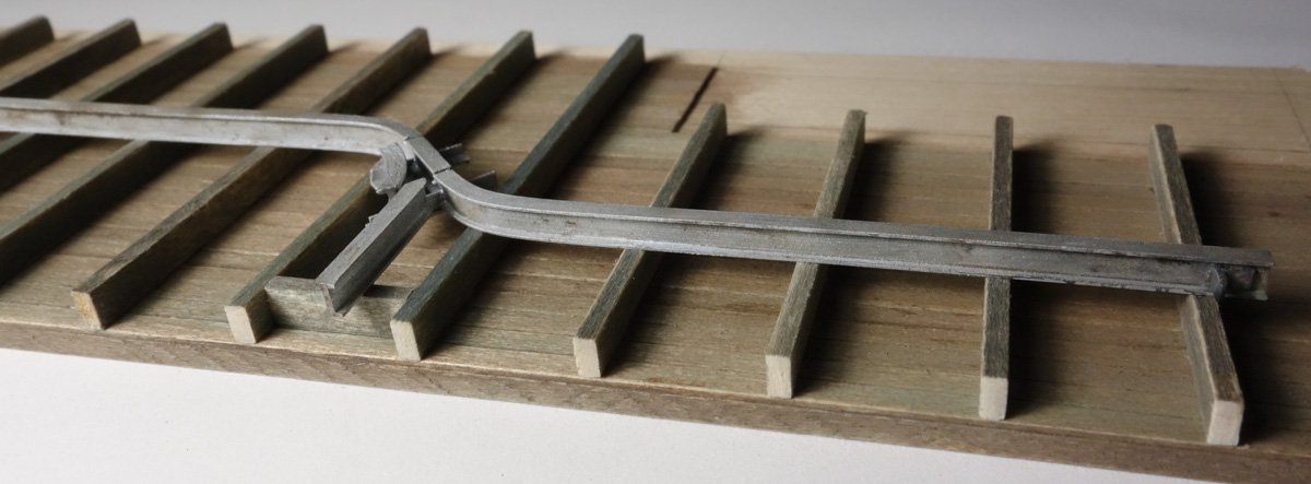
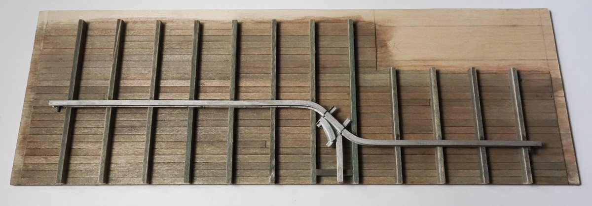
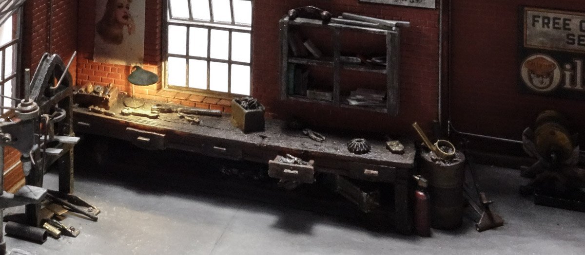
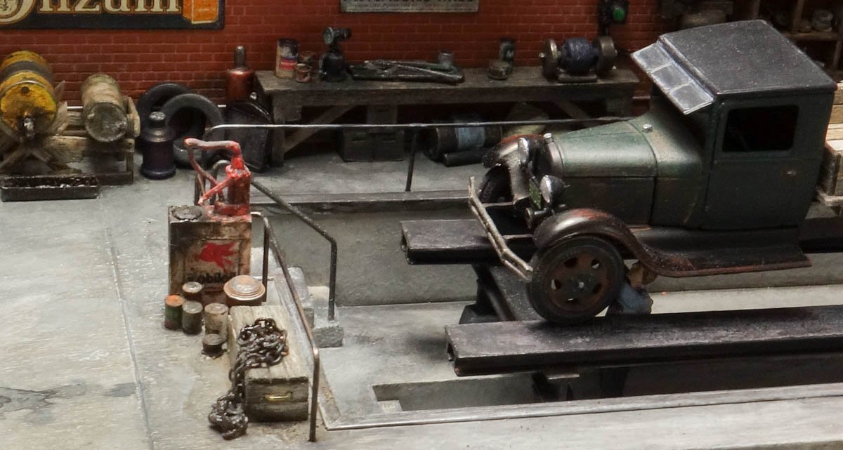
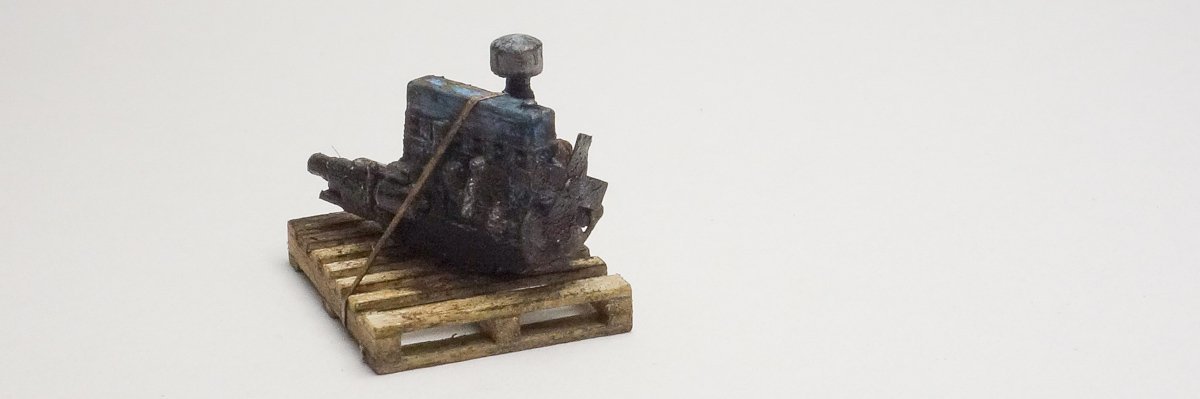
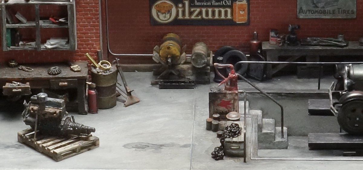
Thank you Gentlemen for the great comments and “likes” and to all for stopping by for a look. Thanks Keith. That's a good suggestion which I attempted with mixed results. See below. Thank you Denis. Thanks Wefalck and I agree the warm color temperature of the light does add an almost nostalgic character. Pallets and skids in non-standardized form existed as far back as 1915 to accommodate the lo-lifting platform trucks that were coming onto the scene and later in the 1920s for the hi-lifting fork trucks. Admittedly, the one I made represents a more modern version. Ron has stated that the shipping pallet has a patent date of 1939 and I suspect that is when pallets became standardized. Here is an interesting statistic: 450 million new pallets are produced each year in North America alone and there are 1.9 billion in use at any one time. That's a lot of pallets. Thank you Egilman for the kind words and high appraisal of my work. What I like about building a model like this is the freedom to do whatever comes to mind as long as it doesn't stray too far from reality. It's the kind of model where you spend more time researching and thinking about it than actual building it. I agree the tranny is probably a Powerglide or maybe a TH350 - an automatic for sure and not what the time period calls for. But I'm leaving it as I don't have the skill to modify it in a way that would improve the piece. It's discouraging to spend a lot of time making a thing worse. I like your suggestions about the chain and the blocks under the motor mounts, so please read on. Thanks so much OC. Thanks for taking the time to look that up Ron – I really appreciate it. More Odds and Ends. First a couple of updates on the last post. The newly installed bench lamp highlights an open end wrench which is 2” thick and about 4” across the crowfoot. Besides being totally out of scale, its proportions are also wrong and it needs covered or removed. I like Keith's newspaper idea and I think it would have worked out great, but I just wasn't able to create a believable miniature of one. So I tried a magazine/book made from tissue which is much easier to do. I don't know what these guys have been reading, but it isn't Field & Stream. More like little women and not Alcott's Little Women either. But here is the problem, the bench lamp makes you look at whatever is under it, good or bad. It draws your attention away from stronger elements and has you focus on a weak one. The opposite of what I want. The big fat wrench and the little women don't cut it, so I decided to put a figure there working on a nondescript something. I cut the poor fellow's arms off and repositioned them to look as those he is grasping the object. I positioned the figure to block direct light from shining toward the center of the viewing window. This casts his shadow across the open floor, creates contrast and adds depth to the diorama. Next is the inline six. Egilman made some heads-up observations on the engine - one being that the engine should be braced or blocked to keep it from falling over. Also, it would more likely be chained down instead of strapped. Signode made steel strapping systems way back in the 1910s and 20s but it was mostly used by manufacturers for baling product for shipping and it is unlikely that it was used by small shops, so I removed it. I glued some angle bits of styrene to the engine to represent motor mounts and then added basswood blocking and chain. I also added plug wires and ran a fuel line up to the carburetor. The plug wires are #39 wire, the same wire I used for the LEDs. Holes were drilled into the head for the wires and then they were ran to the distributor – actually to the vicinity of the distributor, because you can't drill 6 holes into a bit of plastic that is only .045” in diameter, or at least I can't. But I don't like the way it turned out and will position it on the dio facing to the rear so it won't be seen. This will be the side facing front. I'm glad someone computer modeled this engine for 3D printing because it would have been very time consuming to scratch something so small, to say nothing of the research time gathering all the dimensions. It's time for a ceiling, so a template is drawn for the planks and joists. The hoist trolley beam is also positioned and I'll talk more about that in a moment. The ceiling is 8” wide boards glued down to the diorama top plate. The two drill holes on the right end are for the space heater piping to fit into. The wood is colored with art chalk which is scraped off the side of the sticks directly onto the piece. I brush straight isopropyl on to liquefy and spread it around. Water works just as well, but the alcohol dries much faster and lessens the chance of wood warpage. Brown often tends to lean strongly to the red side, so I added some raw umber to gray it down and give it a bit of green. Joists scale to 6”x12”. The trolley beam has a 2-way glide switch that allows the trolleys to travel onto a branch beam. The branch beam points directly at the front glass and is included only to suggest that the diorama shows only a portion of a larger shop. The “I” beam is 1/8” tall styrene from Evergreen. Glide switches work by manually pulling ropes which shuttles the beam segments and redirects the trolley. I found this drawing of one on line. The photos below show the top view of the switch under construction. The switch is flipped over and this is the downward facing side. Trolley stops at the beam ends are added followed by paint. Thanks for stopping. Be safe and stay well. Gary
- 189 replies
-
- 21
-
-

-
Brig Le FAVORI 1806 by KORTES - 1:55
FriedClams replied to KORTES's topic in - Build logs for subjects built 1801 - 1850
I’m so glad to see you working on a new project Alexander. Your La Jacinthe is such a beautiful model and your build log of it was educational and very inspirational. I know this new build is also going to be excellent and I look forward to watching you bring it life. And what a great start! Gary -
Very nice work Dan, looking great. Gary
-
Nice progress Denis - the paint looks great! Gary
-
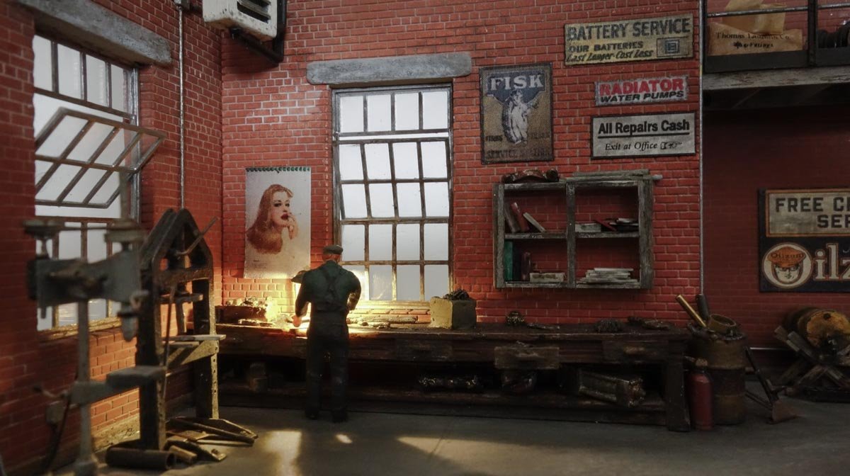
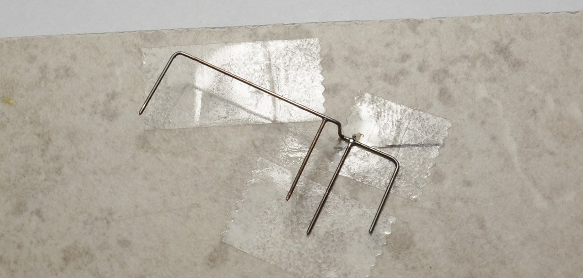
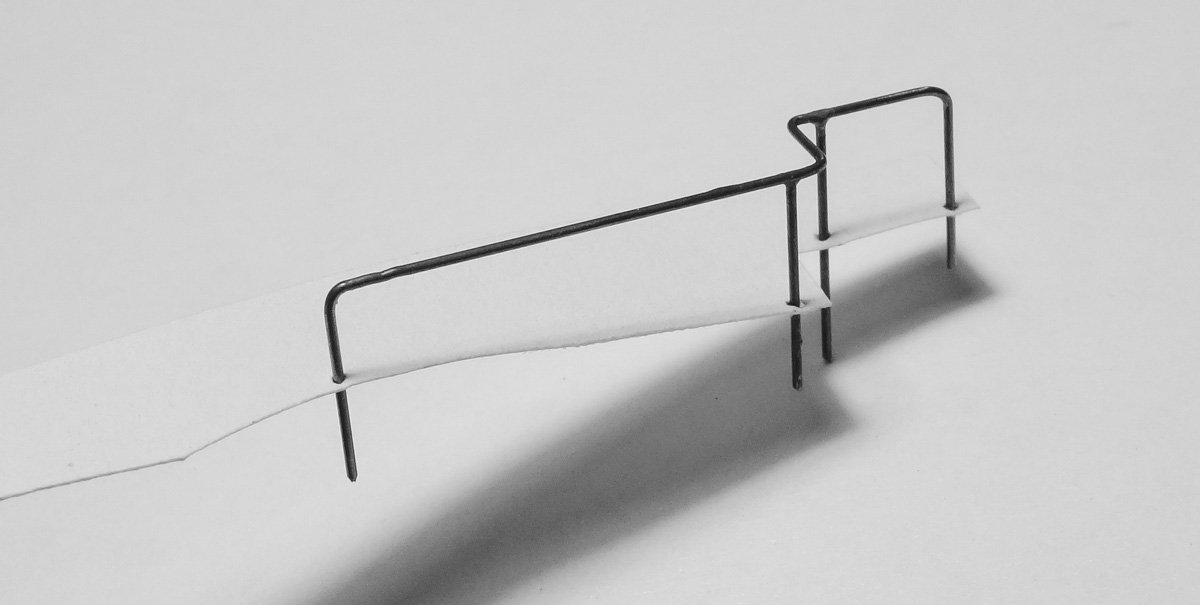
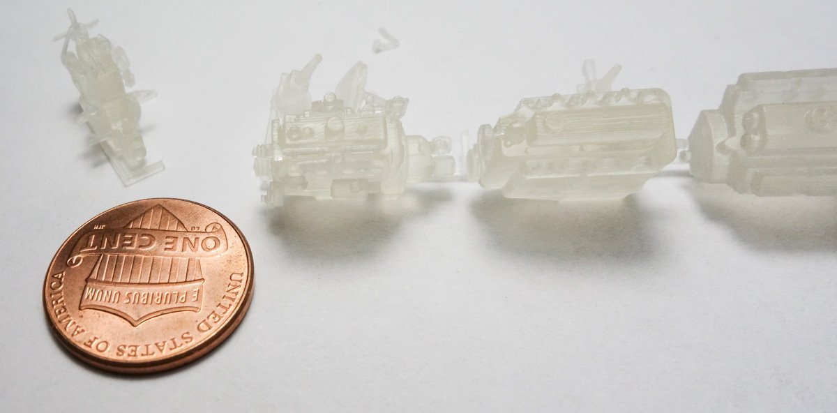
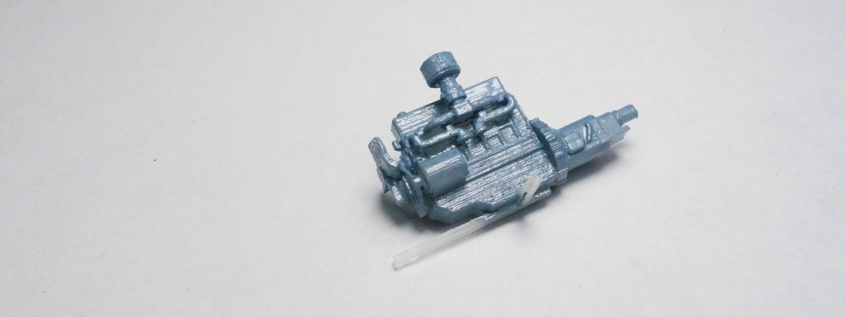
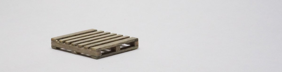
Thanks to all for stopping by and for the "Likes". Here's a short update on some odds and ends. From the last post, the bench lamp has now been placed. Unfortunately, it shines on and highlights one of the worst looking hand tools on the bench. I may have to scrape that wrench off. The pit needs a safety railing next to the stairs, It is made from .022” phosphor/bronze soldered together. I decided not to place a railing along the front, up close to the glass because it would only be a visual distraction. To help locate the railing drill holes on the diorama, I push the uprights through a piece of paper and use it as a template. After the railing was placed, the lubester (from page 3 post 72) was glued down along with other stuff. There is an empty space in front of the main work bench, so I decided to place a pallet there with a greasy engine sitting on it. Not wanting to spend hours scratching an engine in 1:87, I looked around and found a 3D printed one on Shapeways that looked quite good. Although this engine was not labeled or otherwise identified, it looks to me like a straight-6 Chevy. It was one in a set of five different engines. Wikipedia tells me the straight-6 was Chevrolet's only engine from 1929 to 1954 replacing an inline 4 cylinder. It went through different generations and was available in several displacements. It was no longer offered in North America after 1990. On my diorama, I'm calling the engine a second generation 216 which began production in 1937, so it fits my stated time period. Chevy auto forums say these engines were painted a baby blue/gray (not to be confused with the Corvette “Blue Flame”) so that is what I did. Even ordering the printings in their smoothest material, you can still see the print lines quite clearly which only became more obvious after painting. A pallet is made from basswood. After cleaning some of the worst print lines, I grubbed it up with oil paints and powders. I scratched a brass fan blade replacement because the printed one was grossly thick and out of scale. The hold-down strap is paper which measures less than 1/32” wide. The pallet is not glued down yet. There will be a chain fall hoist hanging from overhead so I'll wait until that is in before I finalize the engine position. Also, there will be a little dude wrenching on it. Be safe and stay well. Gary

- 189 replies
-
- 20
-
-
-
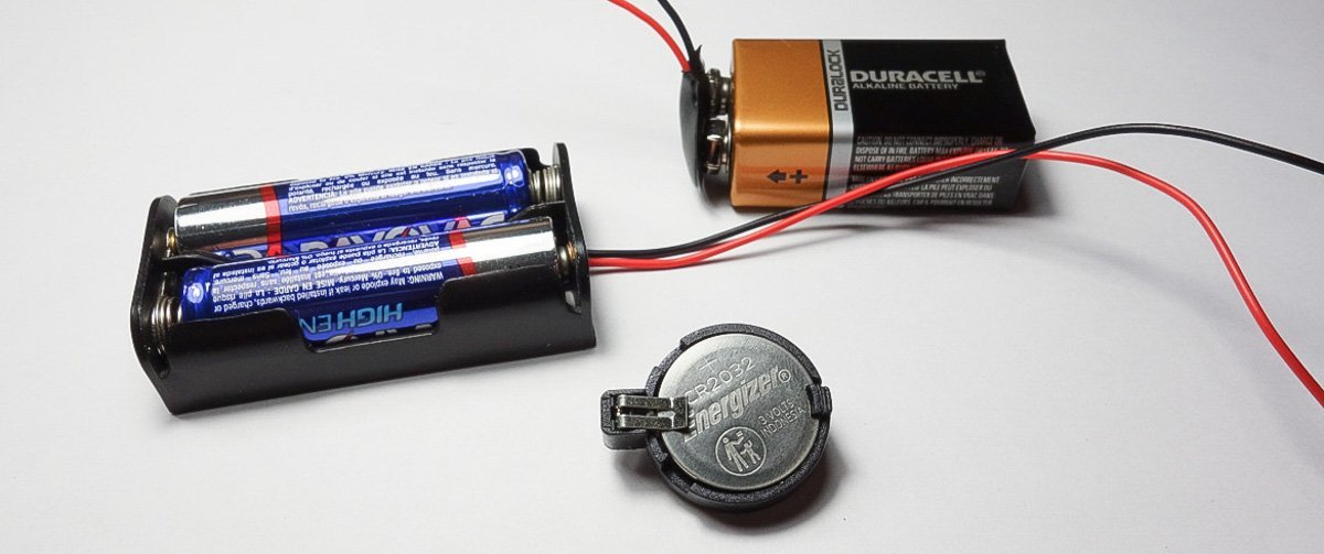
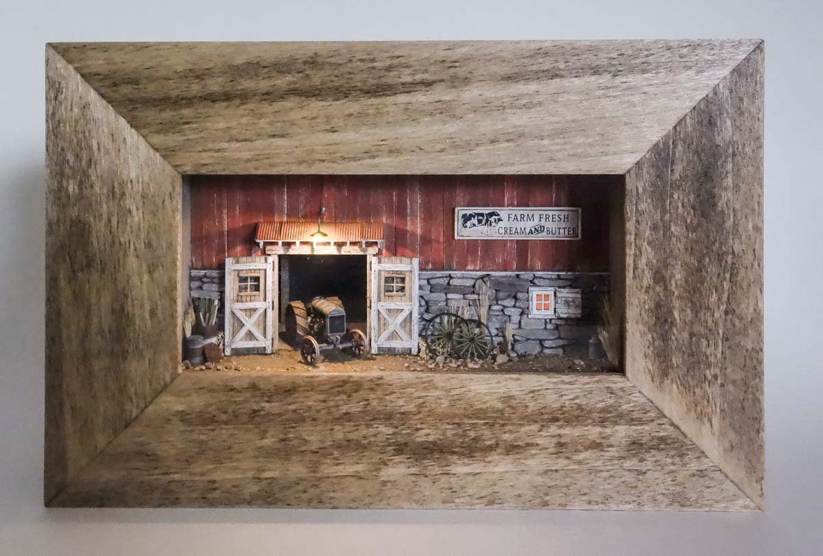
Hello Roger and thanks for the comment. LED life span depends on a number of factors and unlike most semiconductors they degrade slightly over time. So when considering life span, two benchmarks are often quoted - L70 meaning that the device is still emitting 70 percent of its original light output and L50 for 50 percent. If you average manufacturers claims, the typical life span of an LED at or above L70 is maybe 50,000 hours. Running them 8 hours a day they should last for 17 plus years or 5.7 years continuously. I'm not convinced, but that's what they say . And this of course assumes proper circuitry and keeping the device from environmental heat and so on. I use one of these battery holders below. The coin battery and the AA holder both output at 3 volts while the other is 9 volt. What I use in any particular instance depends on the wiring configuration and what and how many LEDs are being used and how they will be used. In the photo below is my farm front mini diorama which simply has two 0603 SMD LEDs each drawing about 10ma each. It is powered by a cr2032 coin battery which has a 225mah (milliamp hour) capacity. The battery should last for 11.25 hours if my calculation is correct. If it were powered by the two AA batteries it could last for 280 hours. I made that dio 5 years ago and I bet the lights don't have more than 4 hours total time on them. I rarely turn the LEDs on and when I do it's typically by request (people do indeed seem to respond favorably to the lighting.) I would never run a cord to these little shadowbox dioramas, but if I had a display that I wanted to have on most of the time, I would use a power supply that plugs into a wall outlet, set it up with a on/off remote w/dimming and ditch the batteries altogether. I hope that answers your question. Thanks again Gary
- 189 replies
-
- 10
-
-
-
-
Thank you Craig and Ken for the comments. I do appreciate it. And thanks to all for the likes. Hello Keith Thanks for following my projects and for your helpful and supportive comments - it's always great to have your views, insights and encouragement. This diorama is indeed getting close to being finished. There are several things yet to do; the ceiling, “outside” lighting, an overhead hoist and a few other minor details, maybe a couple of weeks worth – maybe more. It's been a fun and relaxing build. Looking ahead will be another New England fishing vessel, this time an Eastern-rigged boat. I have purchased copies of the original drawings from which three individual vessels were built in the 1940s and 50s. It is larger than the Stonington boat I finished last year, almost twice the length and more detailed, so at my slow modeling pace it will be a multi year project. But I might build another short term model first, not sure. I've had this itch to scratch a Holmes 750 wrecker and plop it on a military truck that's living a second life in civilian use, or a farm tractor or a Whitehall pulling boat, or . . . Thanks again. Gary
-
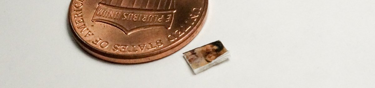
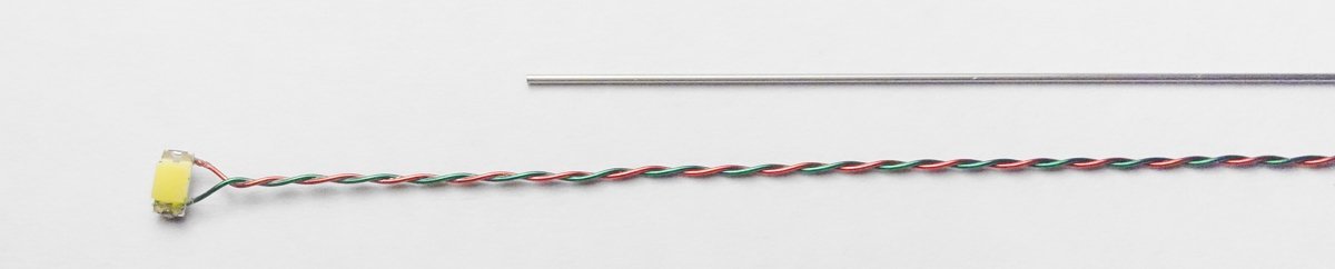
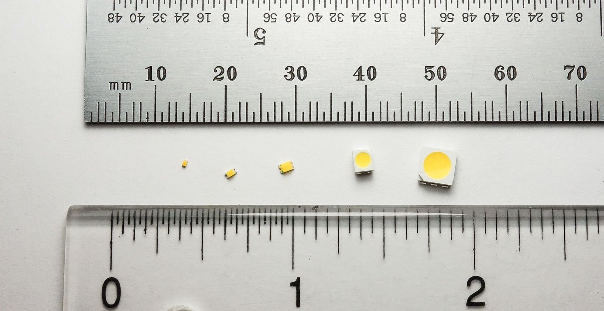
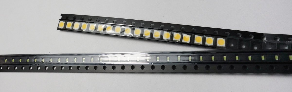
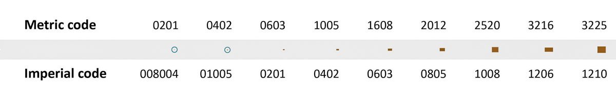
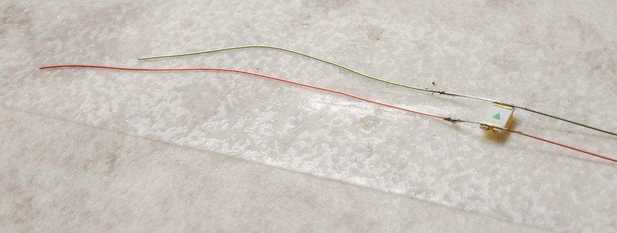
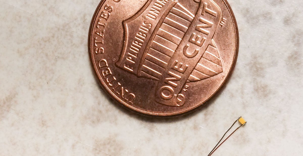
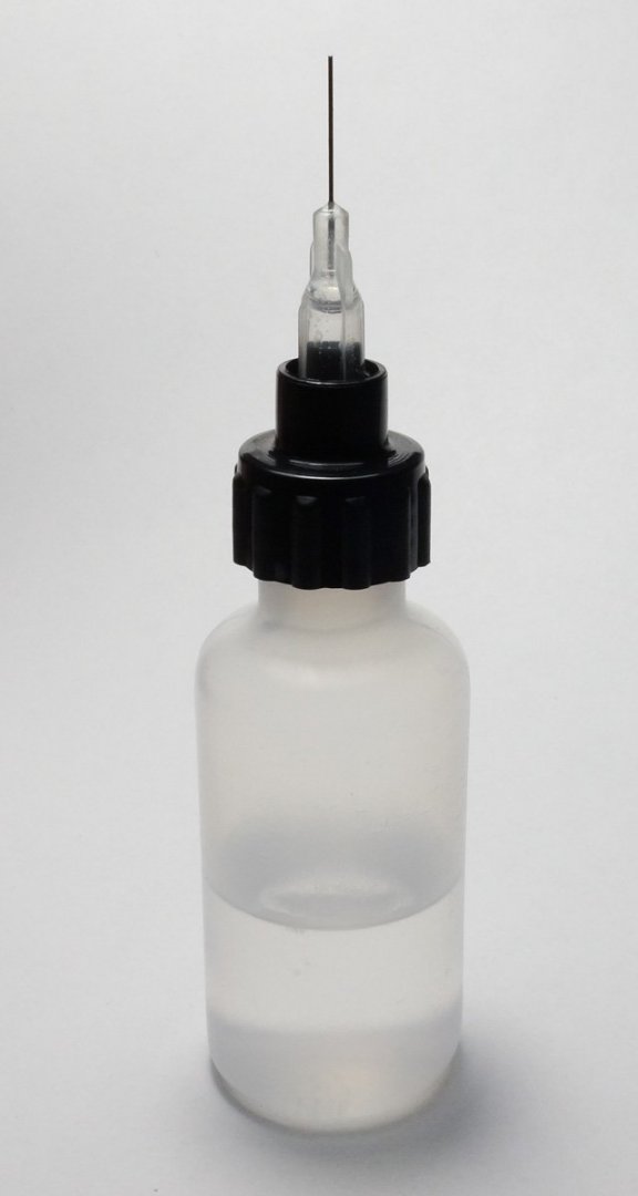
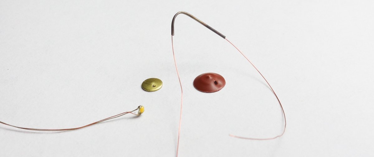
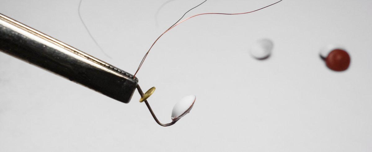
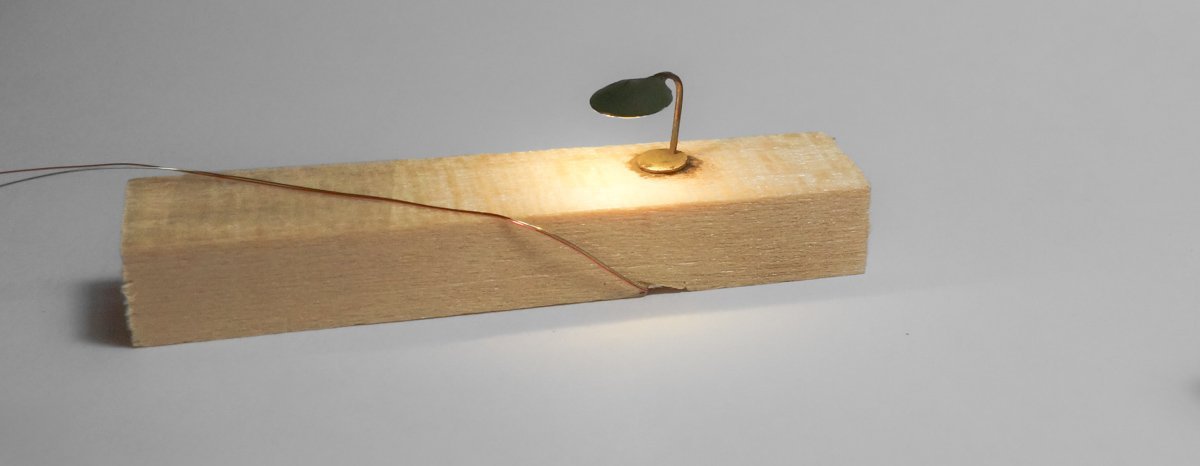
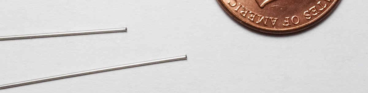
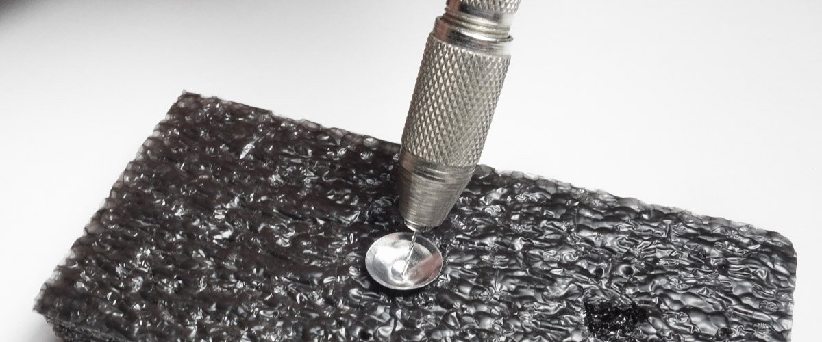
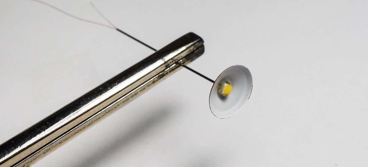
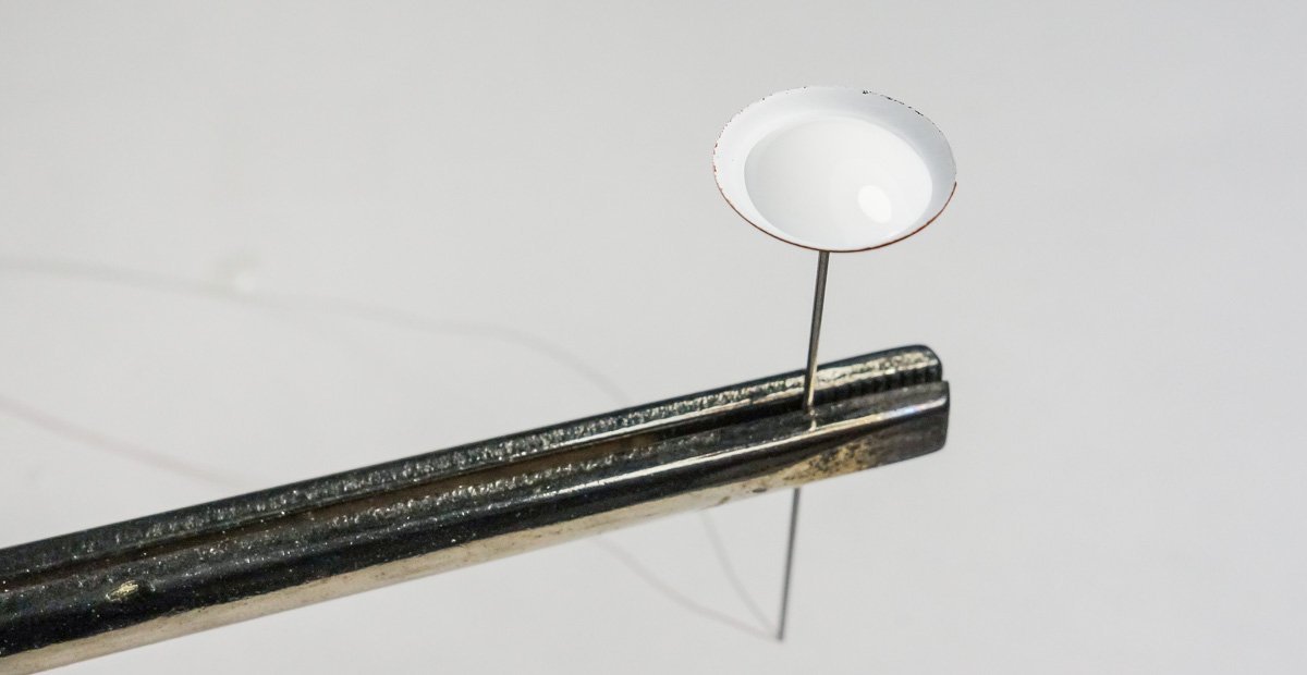
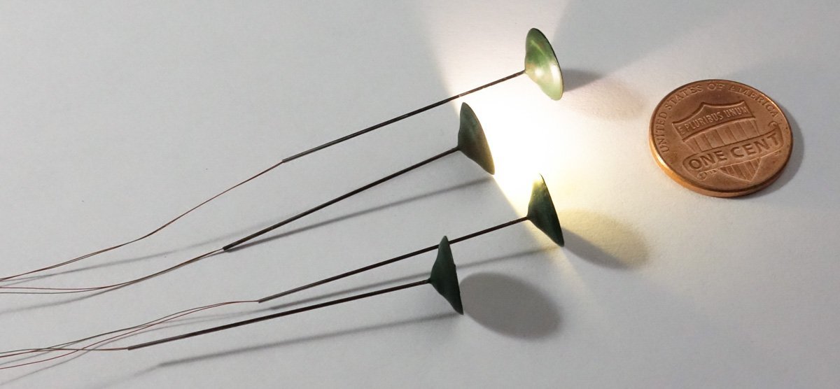
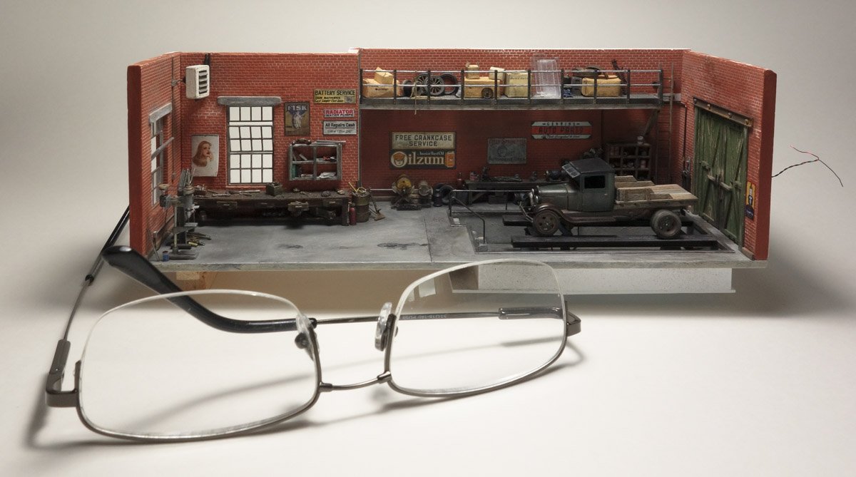
Thanks so much for all the wonderful and generous comments - you folks are so kind. And as always, thank you for the likes and for stopping by. How do you know I'm not 3/4" tall? Interior lighting Prep Work This posting is a bit tedious - I apologize in advance. I put LED lighting on some but not all of my models. There has to be some justification for the effort and the subject needs to call for it. These little dioramas don't just call for it – they scream for it. But in the same way that bright colors can sometimes make small scale models look toy-like, so too can bright lights (or too many of them.) This diorama would be difficult to view without lighting and it will add greatly to the ambiance providing I don't botch it. There will also be “daytime” through-the-window” lighting which I'll explain in an upcoming post. In addition to the drop light under the vehicle, there will be four pendant lights hanging from the ceiling and a single bench lamp. The pendant lights hang off conduit that roughly scales to a little larger than 1” trade size pipe. The “pipe” is stainless tubing and has an inside diameter of .013”. As you can see in the image below it is quite small and yet if I had something smaller I would use it. The problem in using small tubing is that there are no prewired LEDs with fine enough wires that will fit through such tubing. Here is a prewired #0805 LED (the size I will be using) and clearly it will not fit down that tubing. So I solder my own using a simple process that makes soldering fine wires easy and almost enjoyable in a deranged sort of way. LEDs can be bought in strips that were cut from reels for literally a cent or two apiece, so when I smoke one, it doesn't bother me in the least. Here are the sizes I use. From left – 0402, 0603, 0805, 3528 and 5050. The 0402 is small enough that it could be used in an HO scale headlight. LED code numbers refer to the standard SMD (surface mount device) package dimensions and don't indicate a level of brightness. They were designed to be wave soldered onto printed circuit boards, not hand soldered. And confusingly, they are sold by both their metric measurements and their imperial measurements. So a metric #1608 (1.6mm x .08mm) references the same device as an imperial #0603 (.063” x .031”.) If that isn't confusing enough, there is a metric 0201 and an imperial 0201, but they are not the same device and have a completely different footprint. Same is true for 0402 and 0603. I can solder an imperial 0402, but it would take a wizard to hand solder a metric 0402. Point being – buyer beware. I use #39 magnet wire that has a .0038” diameter including insulation and is adequate for feeding a single LED. The insulation is an enamel coating and is better to burn off than to try and scrap off, which damages the underlying copper. With a ball of freshly applied solder on the tip of my iron (almost about to drip off), I quickly insert the wire into the drip before the all flux burns off. This burns off the coating and tins the copper in one step. So after cutting the wires to length, I burn off a 1/4” section about 1” back from the end. This 1/4” section is what gets soldered to the LED connection pads. I place the LED onto a strip of double sided tape and then position the wires over the top and stick them down to the tape on both sides of the LED. This keeps everything in place during soldering. I position the wires so the insulation comes right up to the LED on the right hand side as shown below. I don't care about the other end because those wires will be clipped flush. I then place a drop of “no-clean” electronic liquid flux on the LED followed by a split second touch with the iron in one hand and solder in the other applied simultaneously. No more than a second. One wire at a time with a cleaned iron tip and a fresh drop of liquid flux for each wire. I've had no luck going back to correct a bad solder joint because the solder becomes thick and clingy and the device can't survive the additional heat. It's a fast one shot thing – not difficult but takes a steady hand. I use Kester 951 no clean liquid flux, Kester 83-7145-0415 electronic silver solder (.02” dia.) and a Weller 25 watt pencil iron with 1/16” flat tip. This little 1/2oz. syringe type applicator is handy for the flux. First the desk lamp is made by annealing the stainless tubing and bending it into a gooseneck. The lamp shade is 3/16” diameter aluminum and the base is 1/8” dia. brass. The LED is a 0402 warm white. The pieces are assembled and the underside of the shade gets a drop of “crystal clear” Gallery Glass to insulate and hold the LED in place. It will dry clear and shrink down flush with the shade or close to it. The completed lamp is just over a 1/4” tall, 2 scale feet. I cut four lengths of the tubing for the pendants and work a tiny flange onto one end of each. This mushroomed end will hold the shades and was made by reaming/wallowing with tip of a dressmakers pin. The aluminum pendant shades are from Ngineering. I center drill the domes with a #77 drill bit which makes for a tight fit allowing the flange to hold onto the shade. The shades are primed in and out. The tubing is pushed through the shade and the 0805 LED wires slipped in. The LEDs were encapsulated with clear Gallery Glass after they were soldered and allowed to dry. This insulates the bare connections so I can push it back into the shade without fear of shorting it out. Then another drop of Gallery Glass to hold it firm. The shade tops are painted a heavy acrylic wash over rust colored primer. It looks like oxidized copper (serendipitous and not what I was aiming for, but I like it and must write that down.) Thanks for looking. Be safe and stay well. Gary


- 189 replies
-
- 24
-
-
-
-

-
Hi Tom. Well I found this party just as the last ale was being swallowed. Sorry I missed it. But, what a salvage and transformation! She turned out a very handsome model. Well done! Gary
-
It’s only wasting your golden years if you dislike the work or would rather be doing something else. I’m guessing that you, like most of us, enjoy the physical act of modeling and not the completion of it. Gary
-
400 - 450 blocks, dang. They look great, like they belong there and have always been there. Nice progress Keith! Gary
-
Found your log a few days ago and I’ve been reading through it. Very nice model Mike and you’re doing a wonderful job. Terrific work on the PE - so small and intricate. Look forward to seeing more. Gary
-
I really like the way this model turned out Alan. Your camo and weathering are very convincing. Nice. Gary
-
Just went through your build log Chris and what a great model this is. Congratulations on its completion. Some of these card models (like yours) are so convincing and impressive in their overall look and feel, that one would never guess it is paper/card. Of course, it is always the modelers skill and care that determine the quality of the final result. You nailed it. Gary
-
It’s unfortunate that the liquid plexiglass didn’t work out as I too think that would have produced an excellent result. I’m happy to hear that you’re not nearing completion as I selfishly enjoy reading this log. Gary
-
Great to see your Tennessee log coming back to life Keith. Even though you were thinking through the rigging and building the model in your head, it can be therapeutic to step back from the physical building to give time for the cobwebs to clear. I’ve always enjoyed reading your log and look forward to seeing you work through the rigging. Your explanations are always clear and concise and I’m hoping to get a better understanding of what I refer to as “all those ropes”. Gary
-
I didn’t know about this either Ken - good to keep in mind. I wonder if spraying electronic contact cleaner on it would be cold enough to work? It would be almost instantaneous and with the nozzle straw you could pin point where to apply it. Gary
-
Isn’t that always the way it goes? Excellent recovery though Denis and like OC. stated the repair is unnoticeable. Nice save. Gary
-
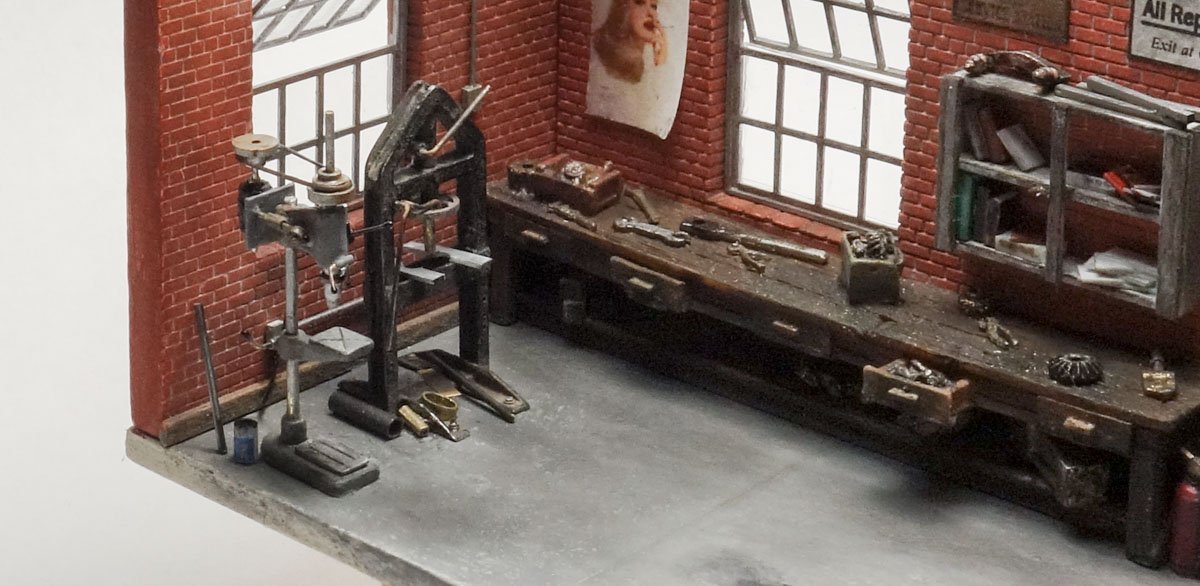
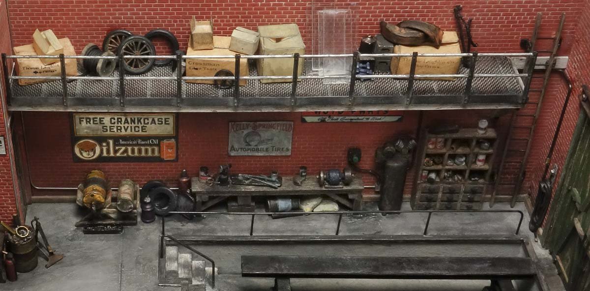
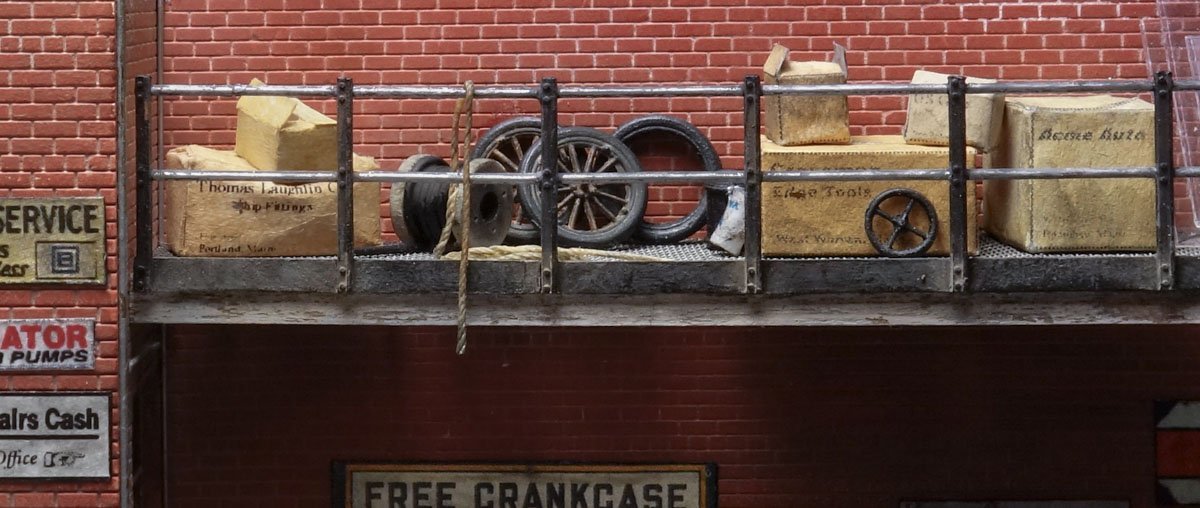
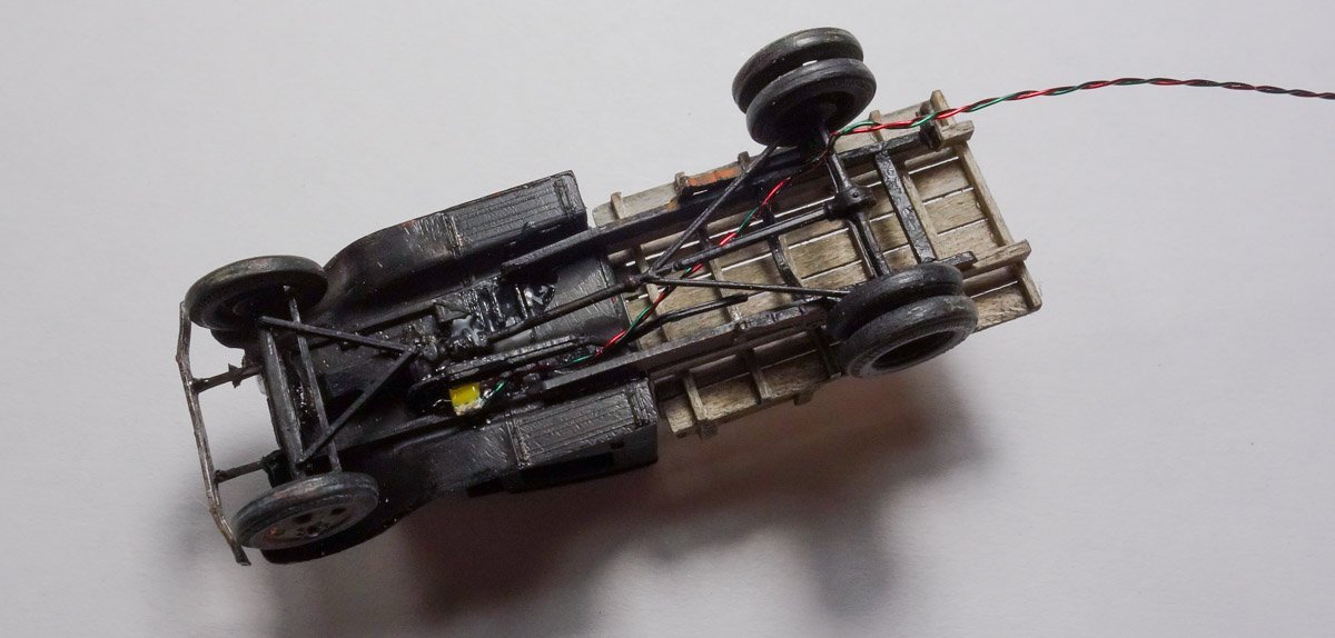
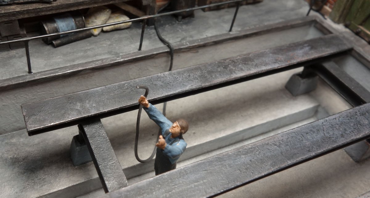
Greetings all. Thank you for your comments, visits and likes. A little more progress to show. I added back the arbor press to the diorama and positioned it where the torch cart used to sit. I moved the drill to the front as far as possible to allow for more elbow room around the press. Moving on, I next populated the mezzanine with stuff. The tires, spoked wheels, fenders and front spring are salvaged from a Jordan model that went all wrong. Everything else is scratched. Corrugated boxes are a quick way to fill up space and are simply folded paper painted with water colors. I decided the mezzanine needed a hoisting rope. It is a piece of miniature rope that has been bleached and re-colored. The bleach removes that starch/sizing (or what ever it is that makes it stiff) and allows it to coil naturally. It was saturated with a water/PVA mix so it holds its shape and stays where placed. This close-up shows me I placed it crooked and needs a little straightening. The underside of the pit vehicle gets a downward facing warm white LED. It is attached with a generous blob of clear Gallery Glass. The stuff starts out opaque but dries crystal clear. It is non conductive, comes in different colors (which can be mixed) and dries translucent like stained glass. Handy. Here is one of the mechanics making an appeal to his Creator asking forgiveness for past sins and his constant use of coarse language. He offers a gift of what he claims is 25' of rubber jacketed electrical cord but is really just a piece of solder. Unmoved by this insincerity, the Creator instead drops a 29 Ford flatbed on his head. The brightness level of the LED will eventually be adjusted down quite low. I hope it will bring attention to the frame structure and keep the pit from becoming a black hole. Thanks for taking a look. Be safe and stay well. Gary
- 189 replies
-
- 32
-
-
-
-
Really nice progress Dan. I admire your tenacity in getting the paint just the way you want it. It sure looks great to me. Gary
-
Very interesting model Denis - I look forward to following your progress. Gary