HOLIDAY DONATION DRIVE - SUPPORT MSW - DO YOUR PART TO KEEP THIS GREAT FORUM GOING! (Only 51 donations so far out of 49,000 members - C'mon guys!)
×


FriedClams
-
Posts
1,368 -
Joined
-
Last visited
Content Type
Profiles
Forums
Gallery
Events
Everything posted by FriedClams
-
 Hello Patrick, it's good to see a posting from you. This is really a very nice miniature - amazing mind boggling details (like the rest of your mini fleet). What is the scale - it seems even smaller than Sapphire and Genesis - could that be? Looks great! Gary
 -
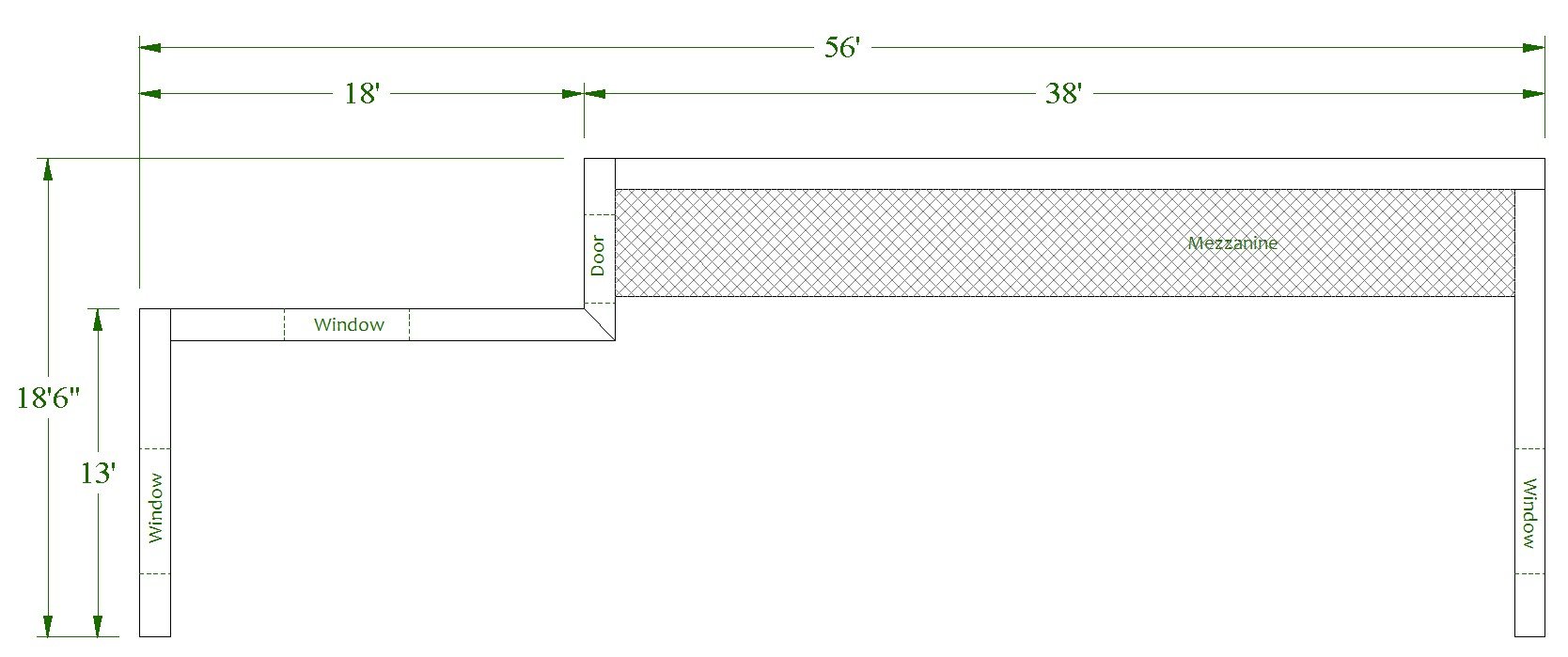
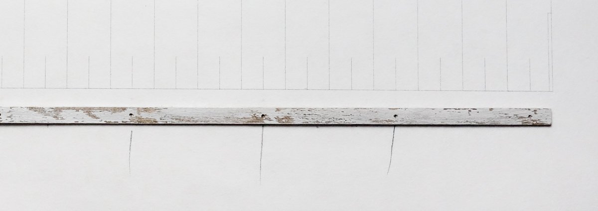
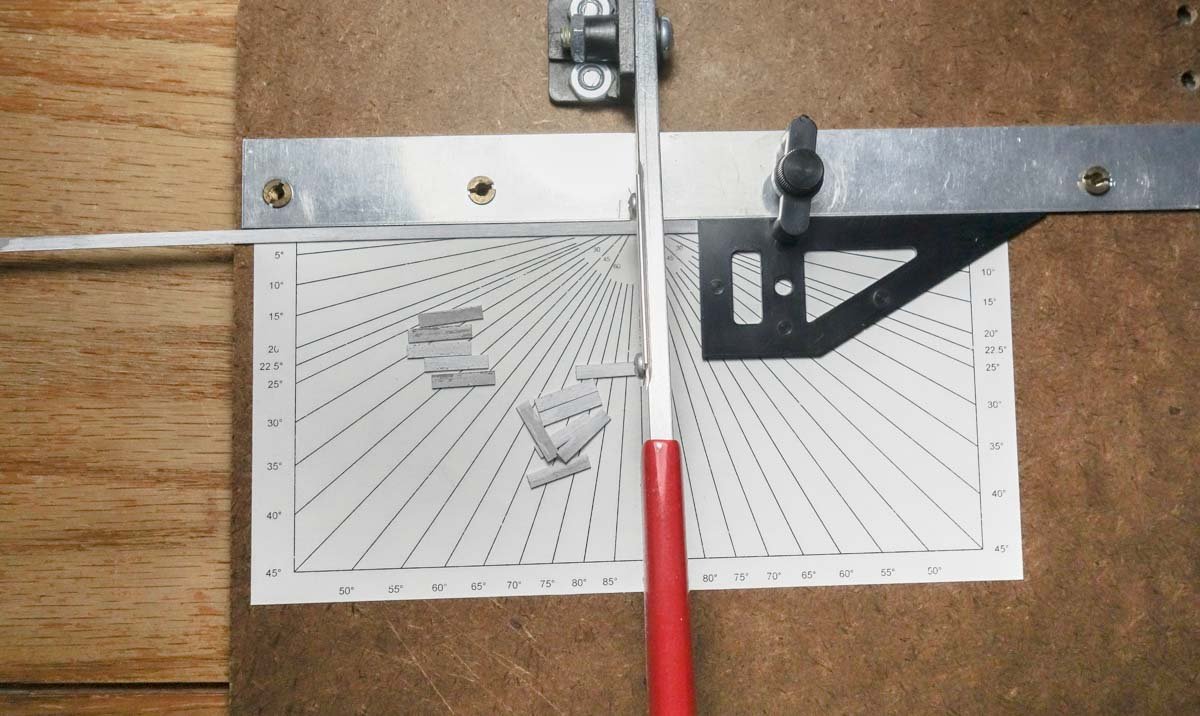
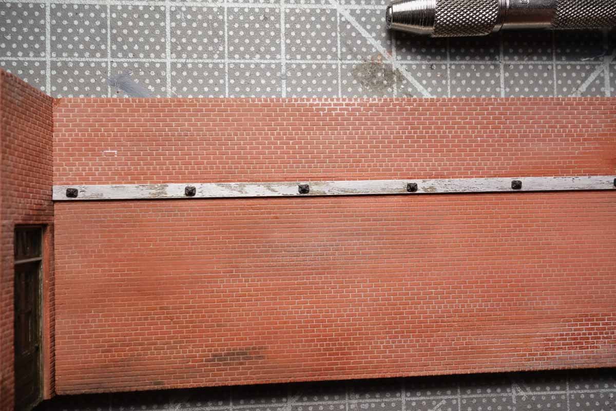
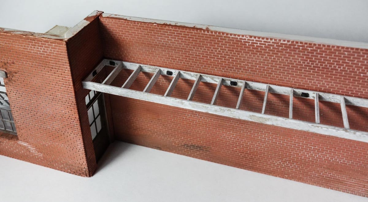
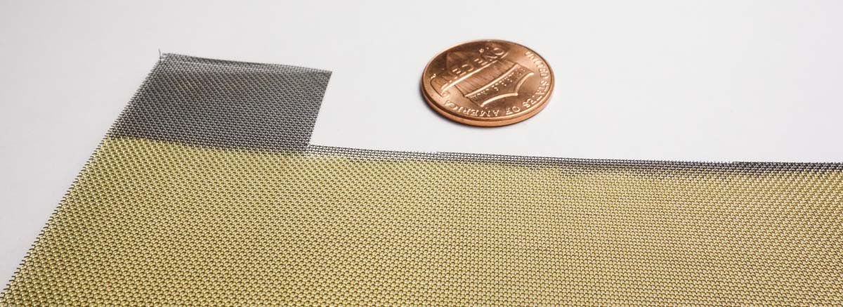
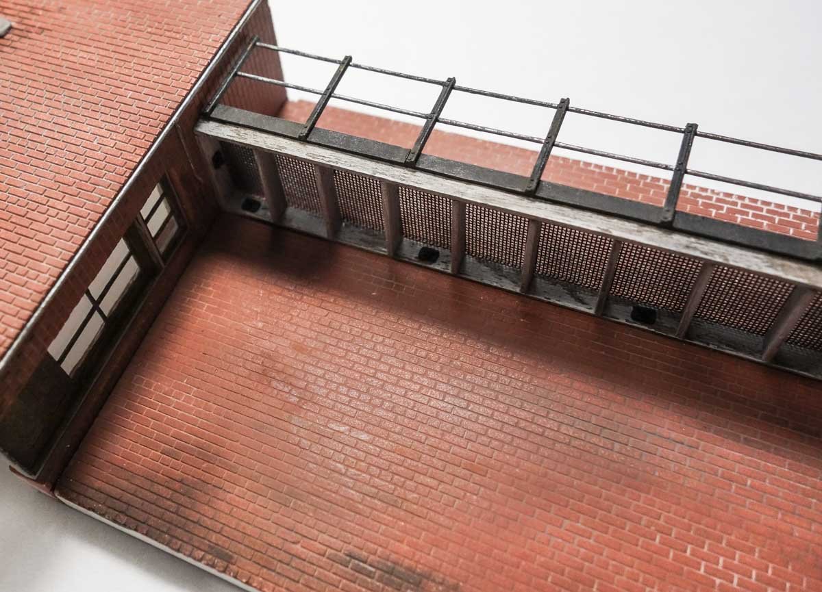
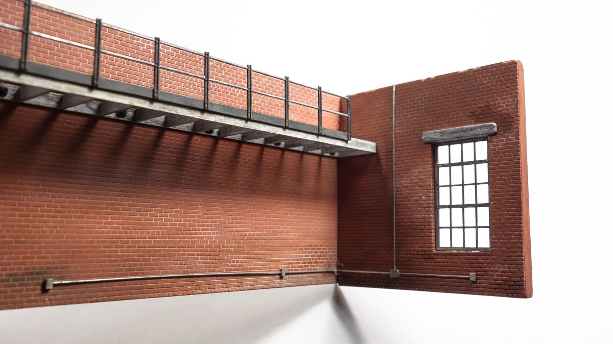
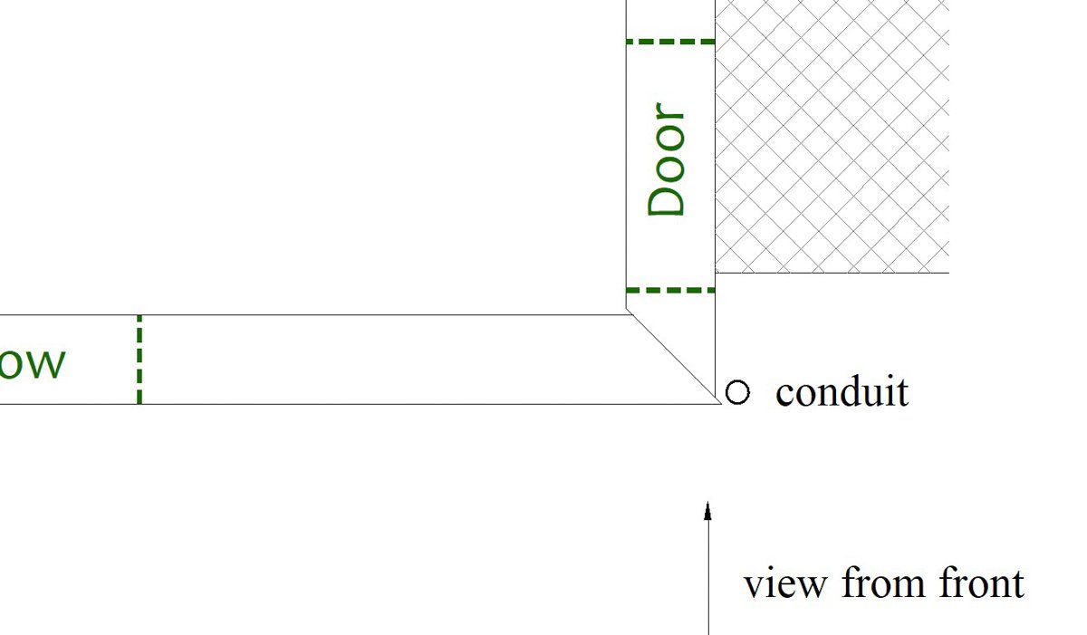
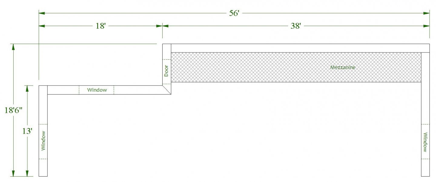
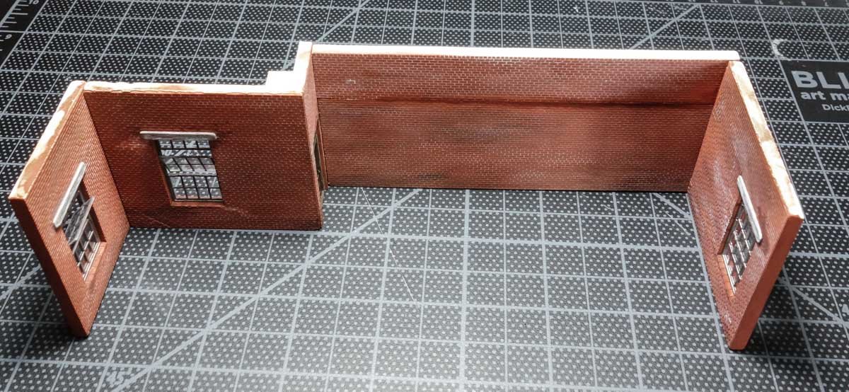
Thank you all for the wonderful comments and support - I really appreciate it. And thanks for the likes. Hello Ron - thanks for stopping by. Yes, as @Egilman has correctly stated they are 45 degree cuts. The short door wall is actually slid back a tiny bit at the joint so it won't be visible from the front. The drawing below is exaggerated but shows what I mean. Also, there is now a conduit hiding the joint. Mezzanine The back wall was pieced together from two chunks of brick material because I ran out of full slabs. But I was able to place the horizontal seam high enough up the wall to where I could place a mezzanine/loft there to cover it. I drew a tick mark strip to locate the platform joists and ledger board bolt heads. The basswood that makes up the frame is scale 2” x 10”. It was stained brown with a chalk/alcohol mix then over painted with white acrylic. After drying for about a half hour, I pulled some of the paint off with regular cellophane tape – stick the tape down, then pull it off like an old bandage. The ledger board was then glued to the wall with CA. The washer/nuts are injection molded from Grandt Line Products. This little chopper gadget makes quick work of producing 17 uniform joists. Using the tick mark strip as a guide, I glued all the joists into place along the rim joist and then glued everything to the ledger board and side walls. The platform surface grate is a blackened brass mesh from Clover House. The mesh size is scale 1.45” made from .0065” wire. The railing is plastic from Tichy Train Group. It's painted black enamel and dry brushed with Testors “steel” and then some pigment powders. Electrical conduit and boxes were added. The “conduit” is .014" brass rod and the boxes are bits of styrene. Holes were drilled into the boxes to land the rod. Boxes with a conduit out each side were drilled through and slipped onto the rod like beads. The next post will bring the project to its present state. Thanks for your interest in this model. Be well. Gary
- 189 replies
-
- 22
-

-

-

-
What a fine subject for a model Druxey. Simple understated lines, yet so graceful and elegant. And thank you for explaining your process in developing the plug. The mystery and magic of art. I'll be sitting in back and following along quietly. And oh, the many uses of rubber cement! Gary
- 433 replies
-
- 4
-
-
- open boat
- small boat
- (and 1 more)
-
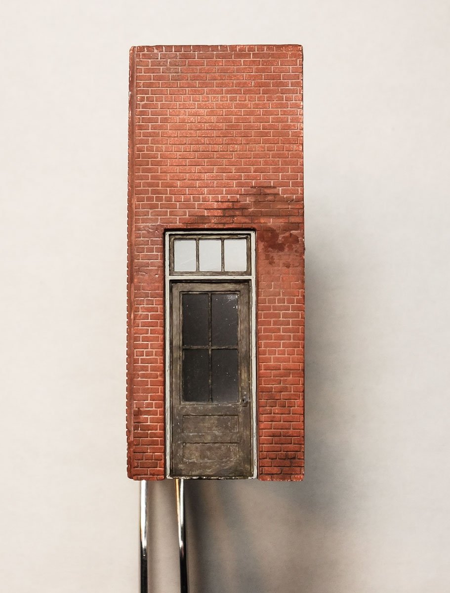
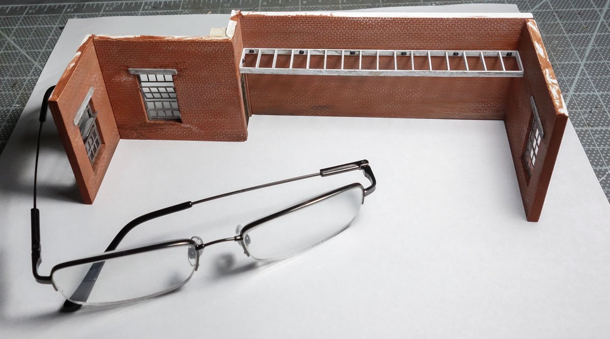
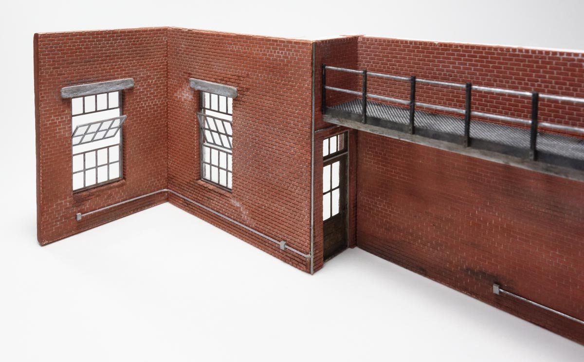
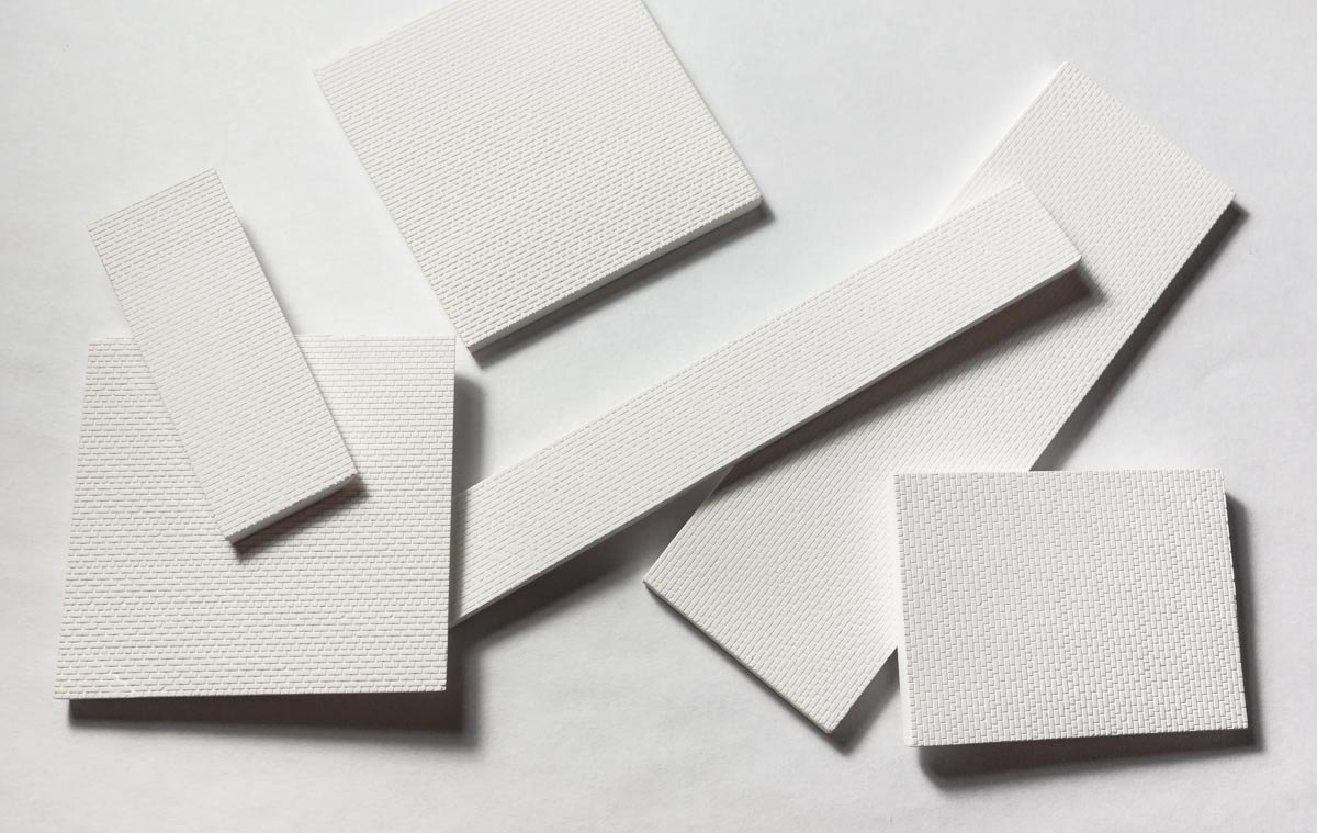
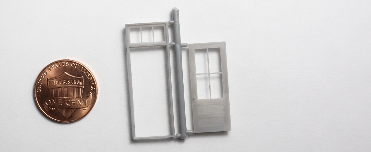
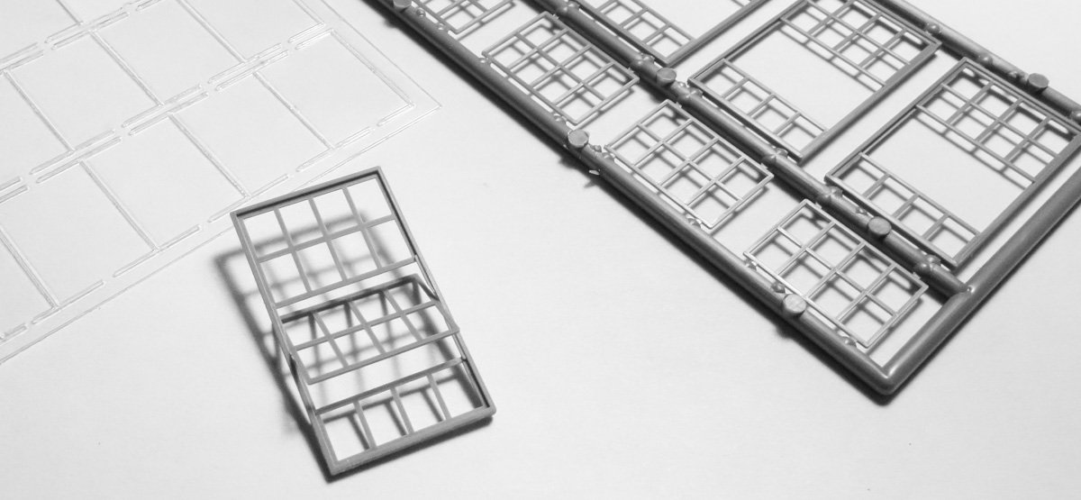
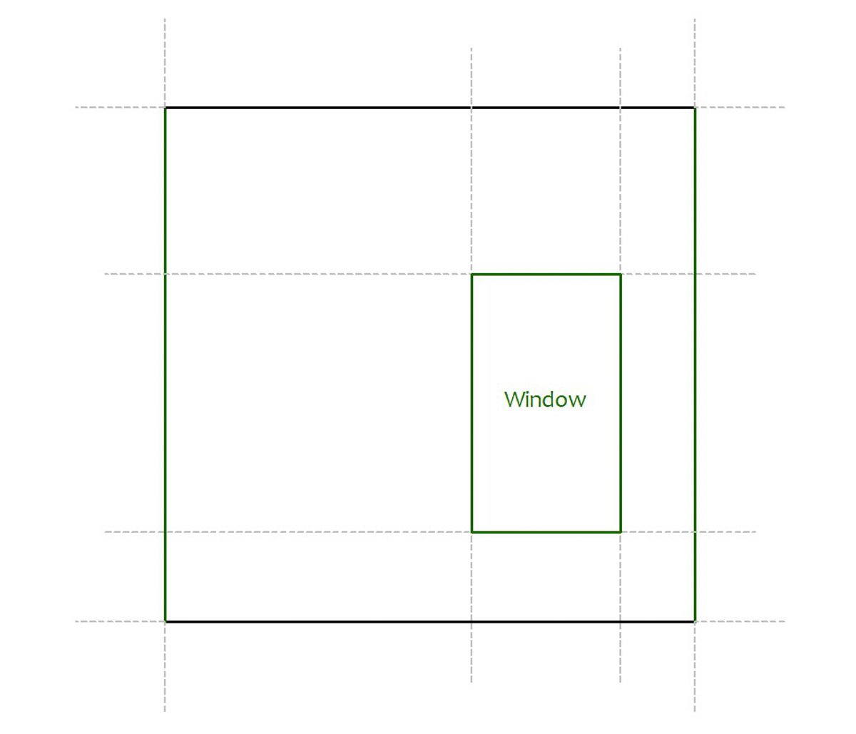
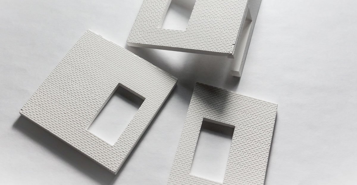
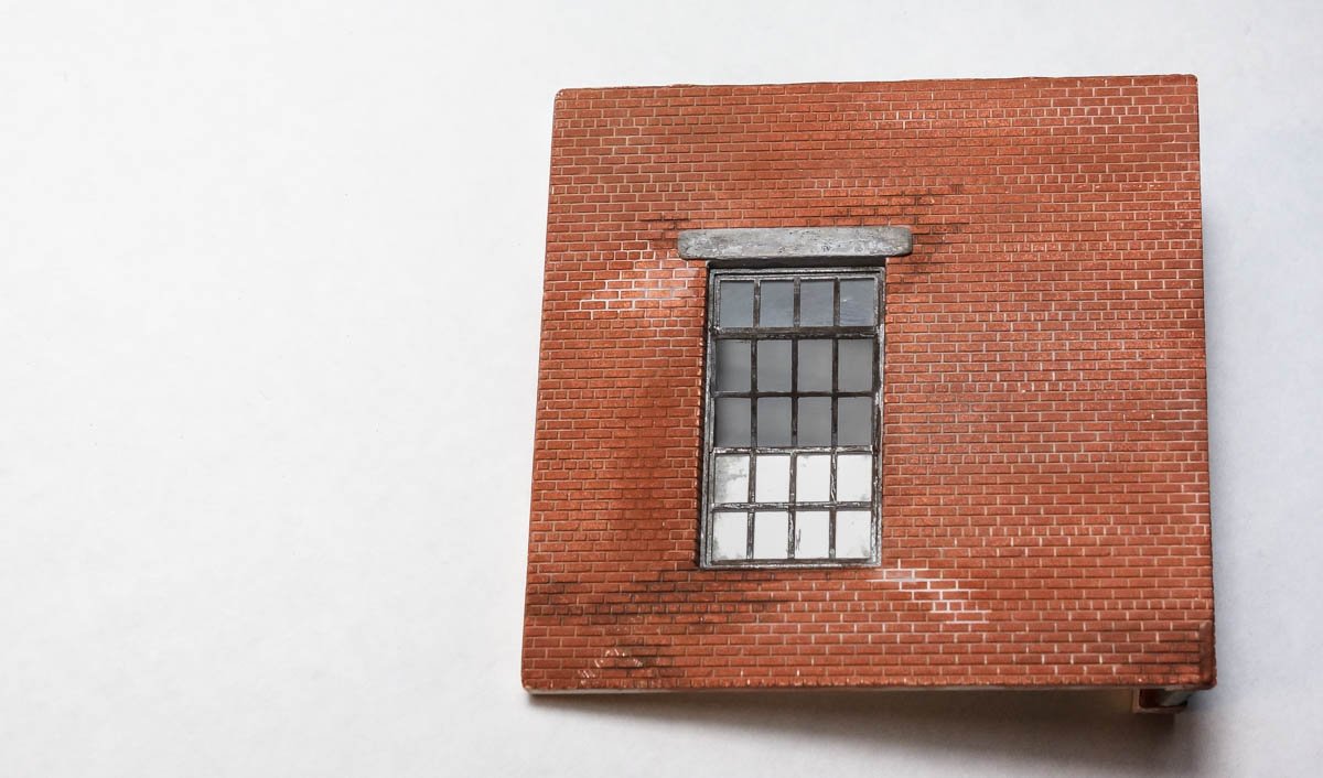
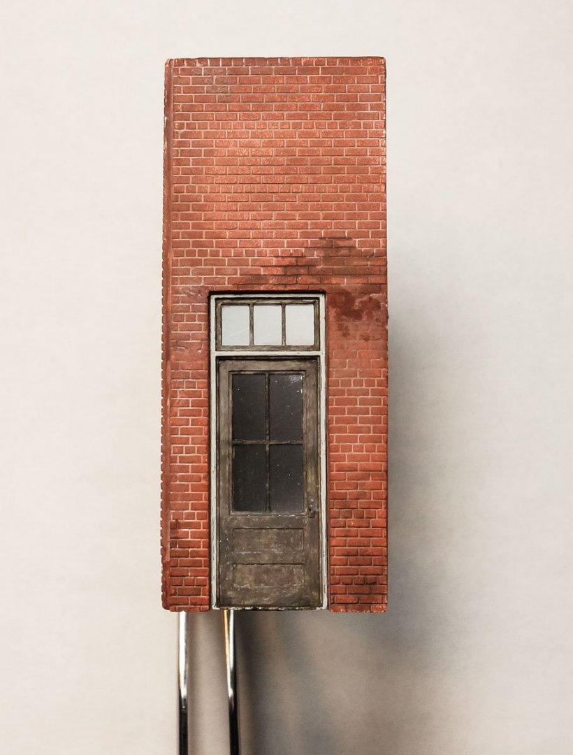
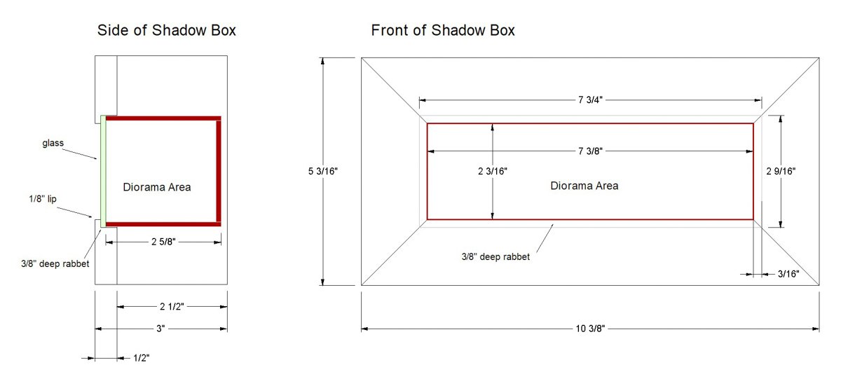
Thanks to everyone for the "likes" and for taking a look. Diorama Walls Now that the case is finished, I have the horizontal and vertical dimensions I need to fit the diorama precisely into the face frame rabbet. So the drawing was adjusted and the wall sections defined as shown below. The windows and door are also located and a storage mezzanine is added. The walls are made of brick that I cut from blank Hydrocal slabs. I purchased the material from New England Brownstone Co. and the stuff is unfinished, about 5/32” thick and in HO (1:87) scale. All the wall sections were cut to size – height and width. The material is cast in the American bond pattern and has a header row horizontally laid every 6 courses, so care was taken in how the wall sections were cut from the slabs so that these courses align with adjacent wall sections. The total height of the walls was also reduced to accommodate the combined thickness of the floor and ceiling. The rear wall had to be pieced together horizontally because I ran out of full slabs of brick. The seam will be covered by the mezzanine support plate. One of the convenient things about modeling in 1:87 is the availability of scratch building materials and detailing parts. I'm using this 39” x 92” masonry door w/transom from Grandt Line Products for the rear entrance. And for the three windows - 60” x 104” 20 pane tilt-out units from Tichy Train Group. These windows even come with laser cut glazing. Because masonry windows have no outer frame casing and must fit into the wall, the cutout openings have to be perfectly square and exact. One misstep which leaves the openings too large or off kilter, and the piece becomes scrap. I began the process by drawing templates for each wall section to assist in locating the cutouts. Carefully placing the wall sections over the templates, I used the outer tick marks and a straight edge to pencil the cutout intersections. The template cutouts are a tad small which allowed me to make adjustments with needle files and achieve a final precise fit. Once I was satisfied, I then cut grout lines around the inside perimeter of the openings. Creating these cutouts was time consuming and tedious beyond measure – razor saw and needle files – filing and test fitting – over and over . . . There are basically two camps when it comes to coloring raw plaster/Hydrocal – those who seal the plaster first and those that don't. There are pros and cons to each method, but here I didn't seal it. I used thinned gouache (not acrylic gouache) and pre-wet the plaster with plain water as I went. I like using gouache because it's dead flat and can be re-activated with water after it has already dried. This is great when I want to do more blending but makes a wash layer impossible. On this model I applied straight burnt sienna over the entire surface of the brick. I later went back and blended in tiny amounts of raw umber to random areas to provide some variation. For the grout I used very watery white and gray. I pre-wet the area where I wanted the grout color to run with “wet-water” and then I just touched a sharp pointed brush (soupy with grout color) to a grout line. In a flash the color raced to wherever the wet-water is/was. The dark areas of brick and grout are where I applied alcohol mixed with a little India ink. The window frames were air brushed a dark iron color (enamel) and dry brushed with silver. The window headers are basswood and simply glued to the face of the brick and painted with acrylics. Then glued together with PVA. Thanks for stopping by. Gary
- 189 replies
-
- 25
-
-
Excellent progress Ken! I agree with the others on the appeal of the low angle photos. Nice uniform oars as well. Gary
- 238 replies
-
- 2
-
-
- sloop
- providence
- (and 1 more)
-
Splendid work yet again Valeriy. Your modeling inspires me to try harder and do better. It has never crossed my mind to make my own chain as you did in post #519 - now I must give it a go. Gary
-
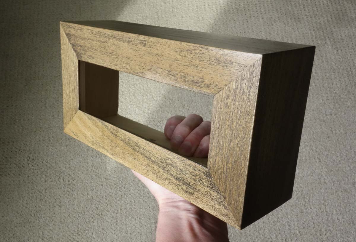
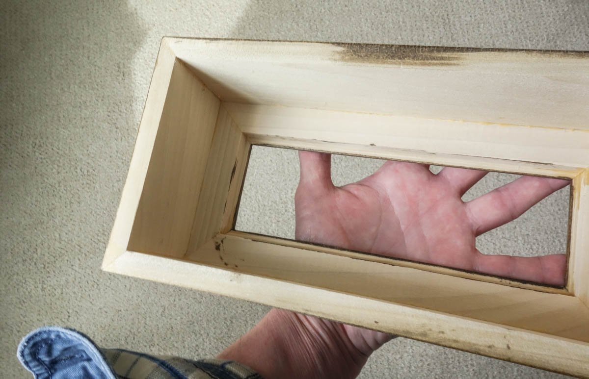
Thanks to all for looking in and for the likes. Hello Keith. It feels good to be starting a new project and I'm happy that you'll be looking in. Yes it will be an American shop because – it's home. We need to have one of our good cousins on the far side of the pond build a U.K. version. You're right Roger, there were many old jalopies held together with bubble gum and baling wire decades after their manufacture, even into the fifties. Heck, I'm still running an old sun-faded Chevy PU that I bought nearly thirty years ago (teenage boys seem to love it and come up and tell me so – funny.) A silver-painted tractor tire as a flower planter – now that would look great on anyone's front lawn. Thank you Yves. I really don't have a lot of special techniques, but yes I will explain whatever I do. And of course I'll be happy to answer any questions you have. Good to have you following Mark. Thank you for the kind words PAPA. The Shadow Box Case The diorama is built as a separate module and simply fits into a rabbeted cutout in the face frame of the shadow box. The shadow box and how the diorama module fits into it looks like this. The shadow box is built first instead of last. I know that may seem backwards, but in the inverted logic of my world I find it easier to adjust the diorama module to fit the box rather than fitting the box to the module. This is because the module needs to fit into the box face-frame rabbet quite precisely – preferably to within a 32nd of an inch all around. I'm not that good with a table saw and my mitered corners are - rarely perfect. So I'll make the module fit the as-built shadow box. The box is made of 1/2” poplar and is simply glued and clamped together. A couple of small beech wood biscuits were also involved. The box was then sanded something like forever and then a coating of pre-stain wood conditioner was applied to help promote uniform stain absorption. Poplar is an easy wood to work with because it's soft and yet holds rather clean, crisp edges. But it sometimes has a greenish grain and it will absorb stain in an uneven splotchy way, so the wood conditioner is a must. The piece is then stained with Minwax Jacobean and finished with a couple of coats of semi-gloss poly. The diorama perimeter is next. Thanks for swinging by. Stay well. Gary
- 189 replies
-
- 18
-
-
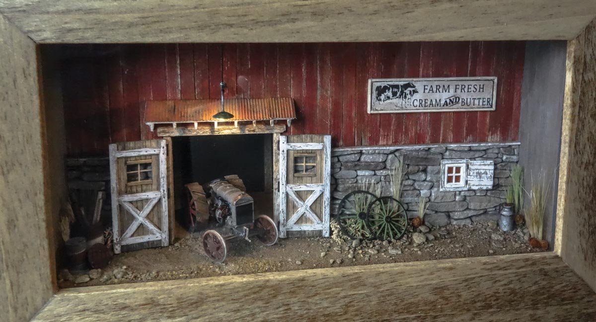
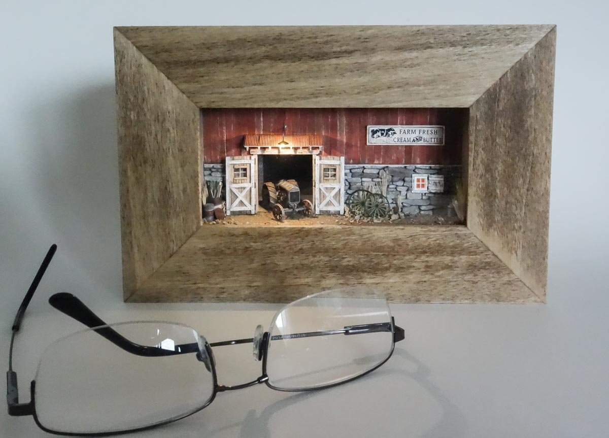
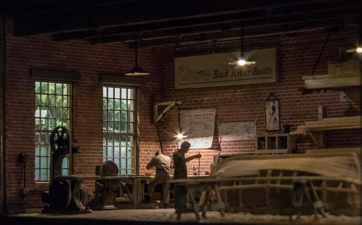
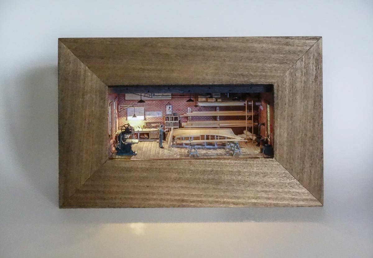
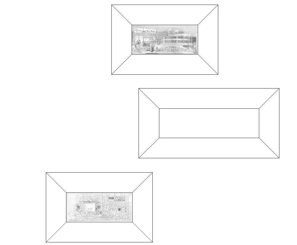
Hello fellow modelers. Several months ago I finished up an eighteen month modeling project of a New England fishing dragger. I am now in the beginning stages of gathering information on yet another fishing vessel that I will begin later this year. But it seems I must always have some project on the work bench, so in the meantime I have begun working on a small 1:87 diorama to fill the void. This is actually the third in a series of dioramas and like the two before it, it will fit into a wall mountable shadow box. In example of what I'm going to be building, here are a few photos of the first two dioramas that I made. In the first one, a Fordson tractor is poking out of a barn door. As you can see, it is not large. The diorama itself is 4-7/8” wide (124mm) by 2-1/4” high (57mm) and 2-1/2” deep (64mm). The second diorama shows the interior of a small boat building shop and is more detailed and ambitious than the first. It has the same physical dimensions. This next diorama will be wider at 7-3/8” (187mm) but the same height and depth as the others. The added width is needed to accommodate the subject matter and will make for a more interesting display when placed together with the first two. I envision a wall display arrangement something like shown below. Other dioramas will eventually be added as time and impulse allow. This diorama will depict the interior of an auto repair garage circa 1940. Clearly, the time period is dependent on the vehicles and at this point I haven't nailed that down. So it could end up being as early as the 1920s. Two vehicles (maybe three) will be in the shop along with repair shop stuff. In the first few posts I will fast forward through the work that has already been done (about 10%) and bring it to its current state. I expect this project to take several months to complete. These little dioramas have been enjoyable short term projects and a change of pace from subjects that float. They're perfect for when I feel like modeling in an offhand sort of way, which is to say - making it up as I go. Thanks for stopping by to take a look. Gary
- 189 replies
-
- 31
-
-
-
I picked up an OptiVISOR two years ago after a decade of resistance and I'm glad that I finally did. Its use has led to the biggest improvement in my modeling than any other tool I own. I'm not exaggerating. And no more eye strain. I bought the set with four lens of varying strengths. I wear my reading glasses the whole time I'm modeling and flip the visor down over the top of the glasses only as needed. I disliked having it on my head at first, but now can't imagine working without them. Beware of inexpensive knock-offs (no, I don't own stock in the company.) The Tennessee is progressing nicely Keith. Enjoy your fresh air activities. Gary
-
Sweet work Vaddoc - the planking is looking great. Gary
-
Terrific work Brian. I especially like the rivet trick and I must try that sometime. Gary
-
I watched the entirety of your presentation last night Eric and thoroughly enjoyed it. A nice overview of the subject and does what all successful lectures/talks do in that it stimulates the desire to learn more. Your passion for the topic is palpable and the organization and pace of your presentation I thought was just excellent. I also appreciate that you did not tip-toe around the catastrophic damage caused to the native tribes and environment by this activity. I have attended more than one historical presentation where the speaker has cherry-picked information to give less than a complete account on the subject. Great talk. Thanks for sharing your presentation with us here on the MSW forum. Gary
- 599 replies
-
- 3
-
-
- sidewheeler
- arabia
- (and 4 more)
-
Very nice Steve, so sleek! I really like the way the base echoes the hull. Gary
-
I love little nuggets of information like this Keith. Small seemingly insignificant tidbits of function can really add so much historical interest to a model. I have always found rigging to be difficult work, but it seems you’re pumped and ready to go. I’m sure it will turn out great! Gary
-
Nice to see you back with an update on your Bluenose Richard. Great work on the chainplates, eyebolts and such. Really like those clamps too. Gary
-
Well, my gob has been smacked almost beyond recognition. Sweet work Michael - Bravo! Gary
-
I just found and read through your log this morning Paul. You're doing a really nice job on the Pauline and progressing nicely. I like that you provided a historical summary of these carriers as it breathes life and interest into the model. I have always found these old carriers to have remarkably graceful hull lines and I'm sure your model will turn out great, as did your Red Baron (sitting pretty on the mantle). Keep at it. Gary
-
Fabulous work Valeriy - the hatch and chain both. The photo at #484 nicely shows how extraordinarily clean and precise your work is. I like your process for making chain and it provides a great result. Thanks for showing how. Gary
-
Just catching up Keith. Beautiful work on the cowl and stanchions, which I have naturally come to expect. And the netting your wife is making is lovely and mind boggling. I can't imagine why. There is something oddly comforting about knowing ones place on the list. Sometimes it's comfort enough just to be on it. Gary
-
Love the work that you're doing here Ekis! Your landscaping, details and photography set the village into a dream-like atmospheric state. Not only are your modeling skills wonderful, but you have the eye of a true artist to understand what needs to be done to achieve that desired effect. Very nice. Gary
-
Wonderful, perfectly executed modeling as usual Johann. Gary
-
Beautiful work Gary, she's looking really smart! I really like the color and tone of the model and your finish work is excellent. The 3rd photo down on post #122 really shows the goods. Nice. Gary
- 162 replies
-
- 1
-
-
- america
- BlueJacket Shipcrafters
- (and 1 more)