
HOLIDAY DONATION DRIVE - SUPPORT MSW - DO YOUR PART TO KEEP THIS GREAT FORUM GOING! (Only 51 donations so far out of 49,000 members - C'mon guys!)
×


FriedClams
-
Posts
1,368 -
Joined
-
Last visited
Content Type
Profiles
Forums
Gallery
Events
Everything posted by FriedClams
-
 Looking forward to seeing you move ahead with this model Michael. But I enjoy all your projects, from steam liner restorations to locos. I learn something new from every one. Gary
 -
Congratulations on a completing your canoe Chris. She looks great and I wish you many hours of peaceful paddling. Gary
-
That's a really good way to think about detail elements, which can sometimes be overdone. Very nice progress Roger. I like your plating method. Gary
-
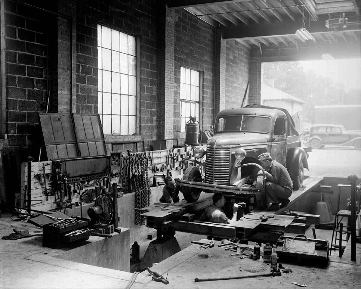
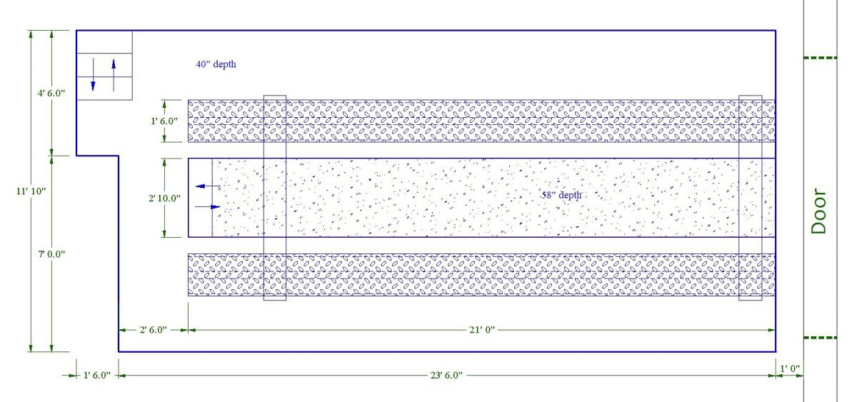
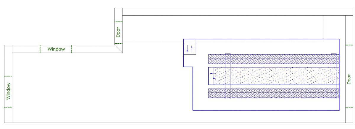
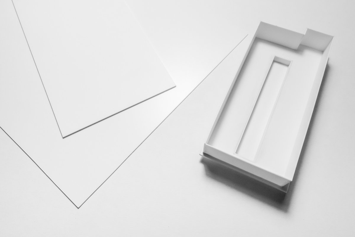
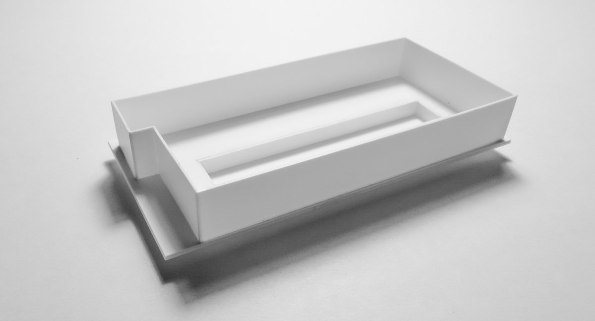
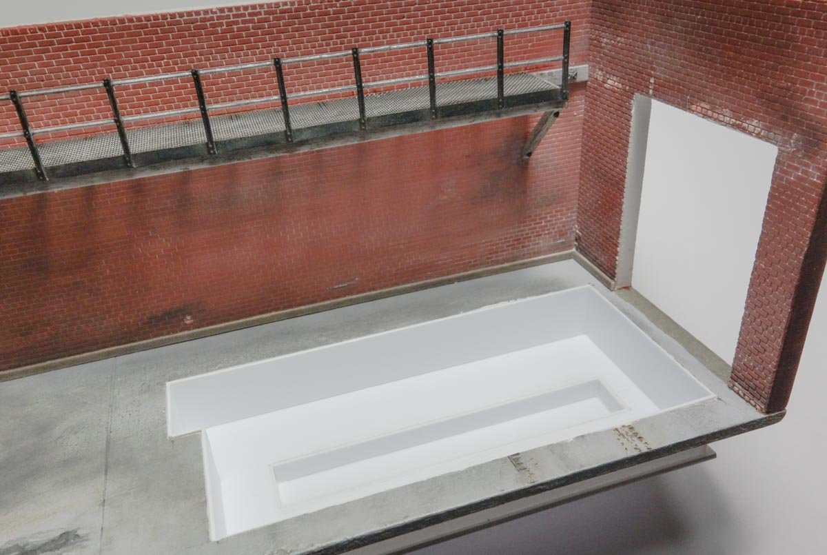
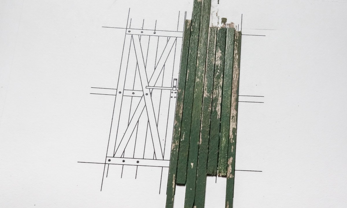
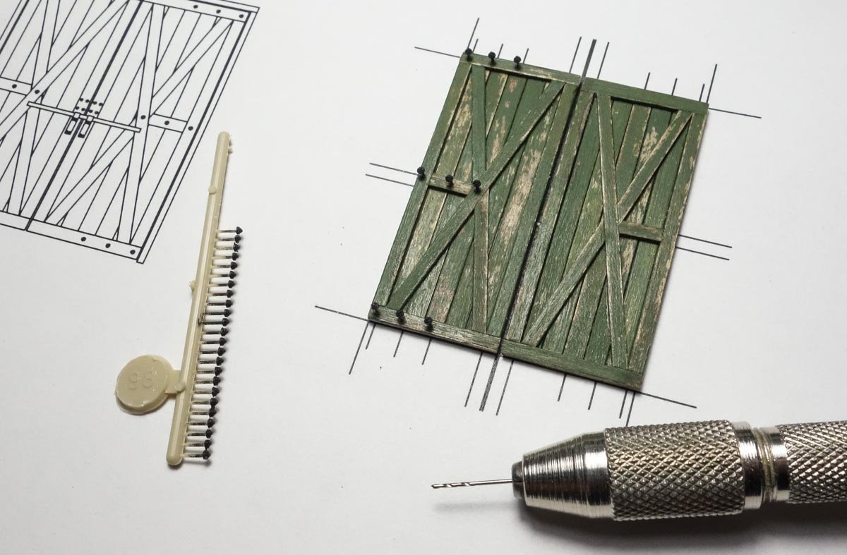
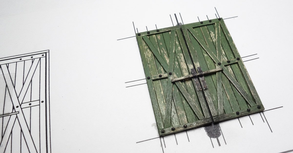
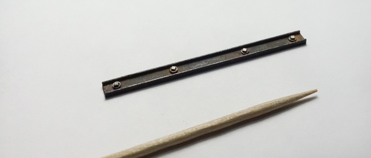
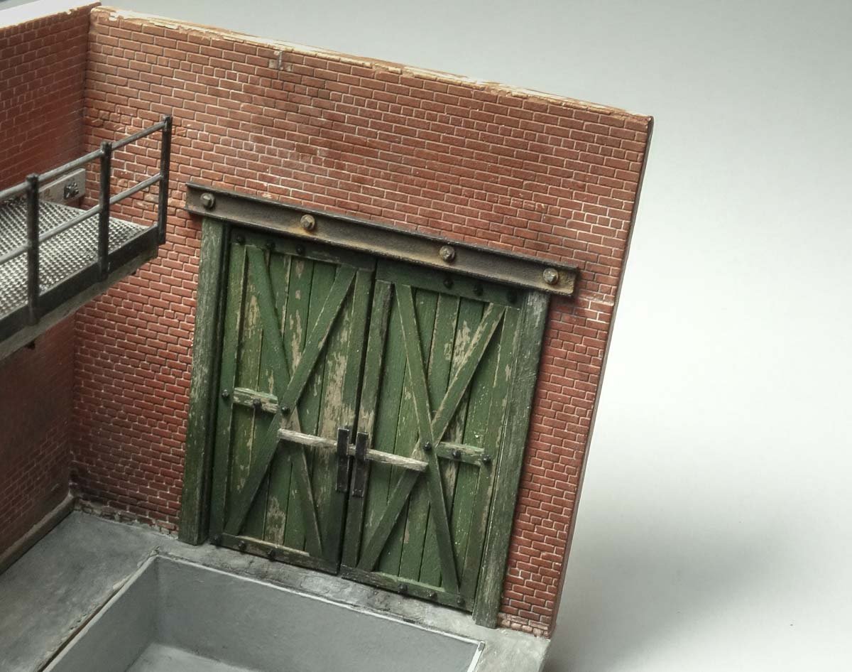
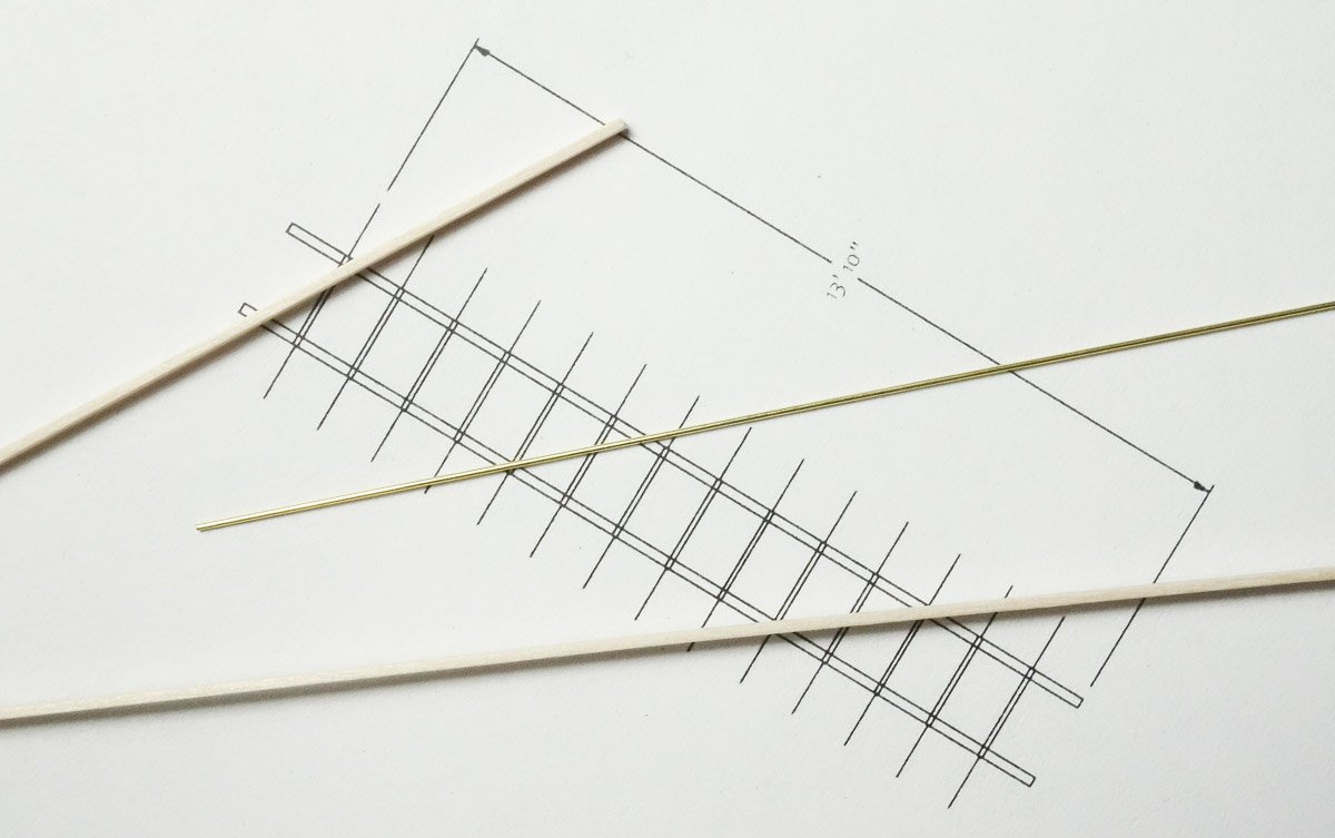
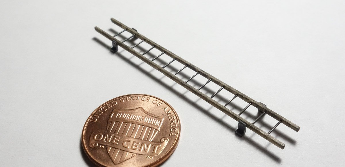
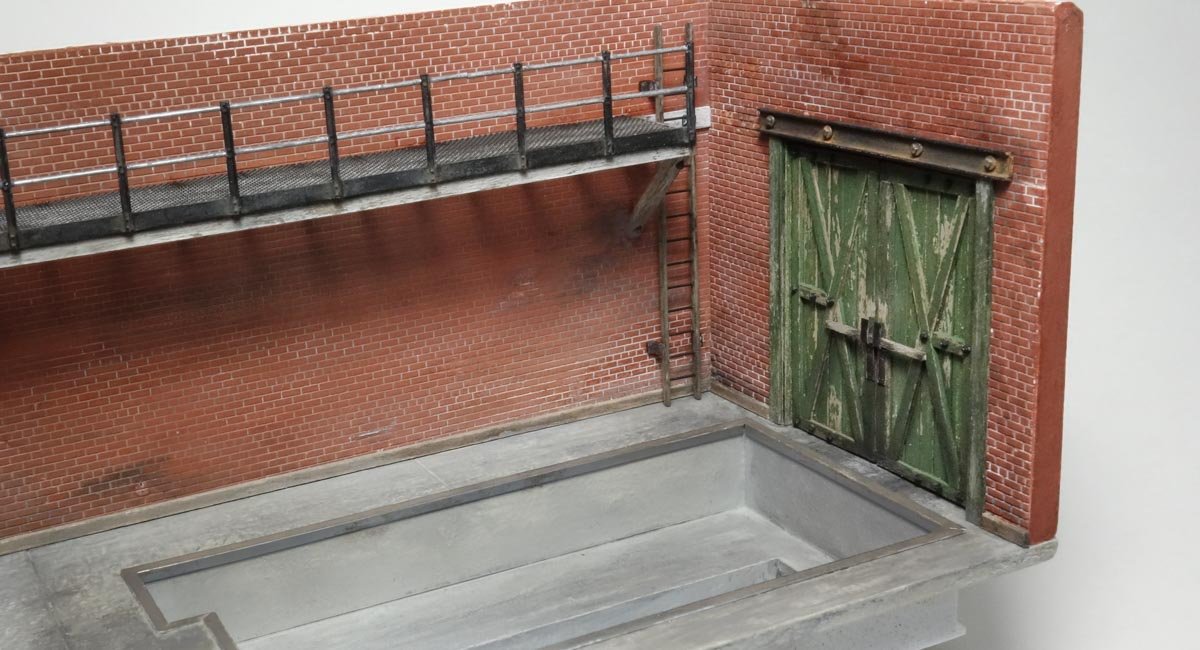
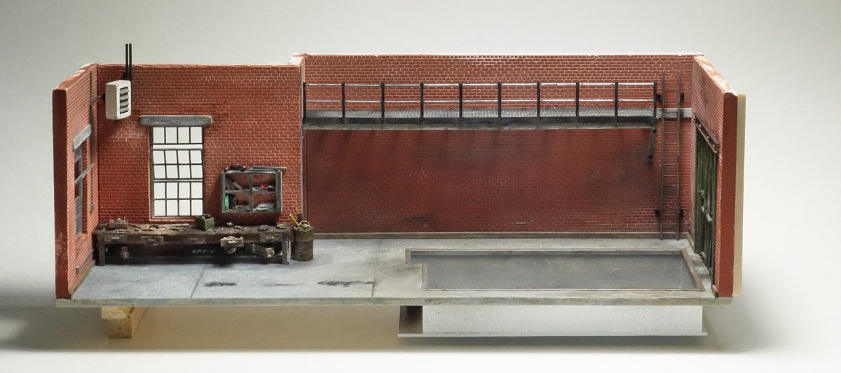
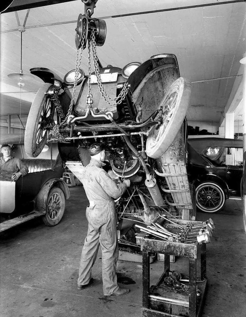
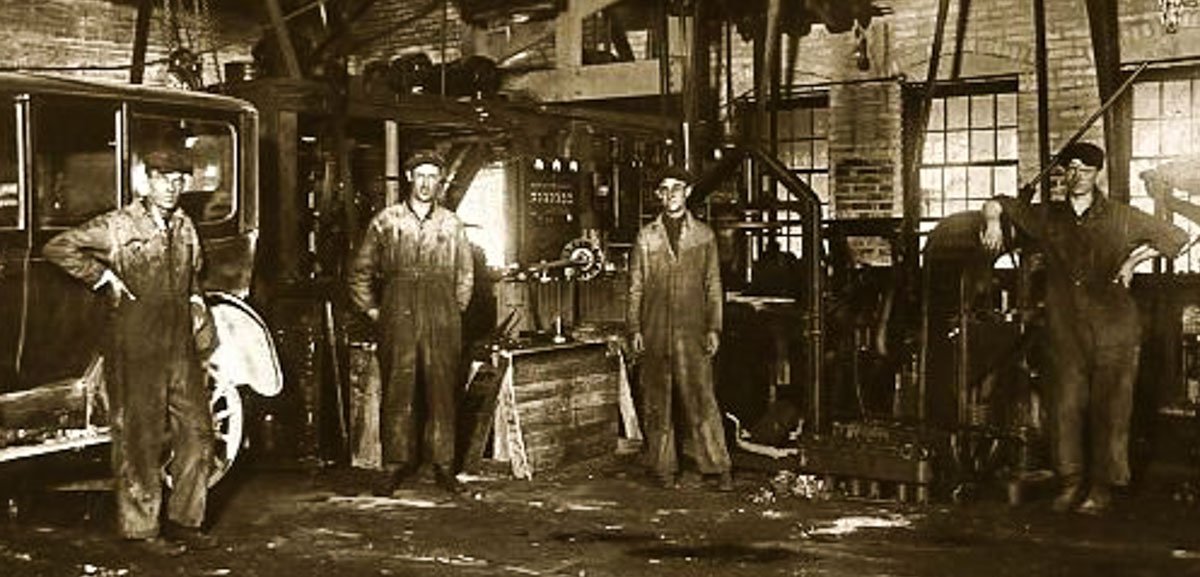
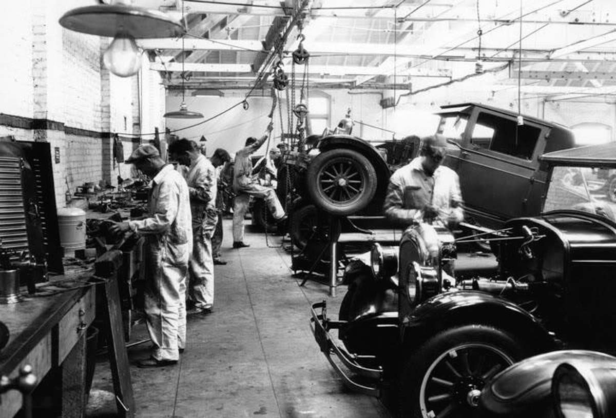
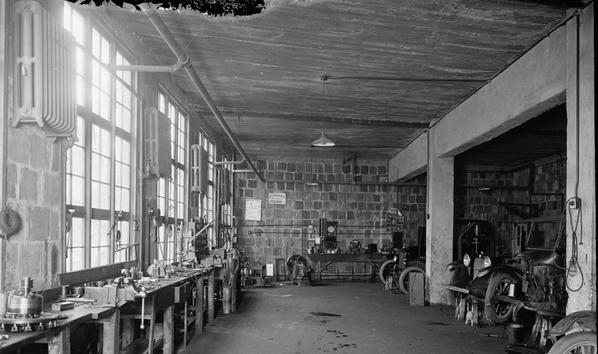
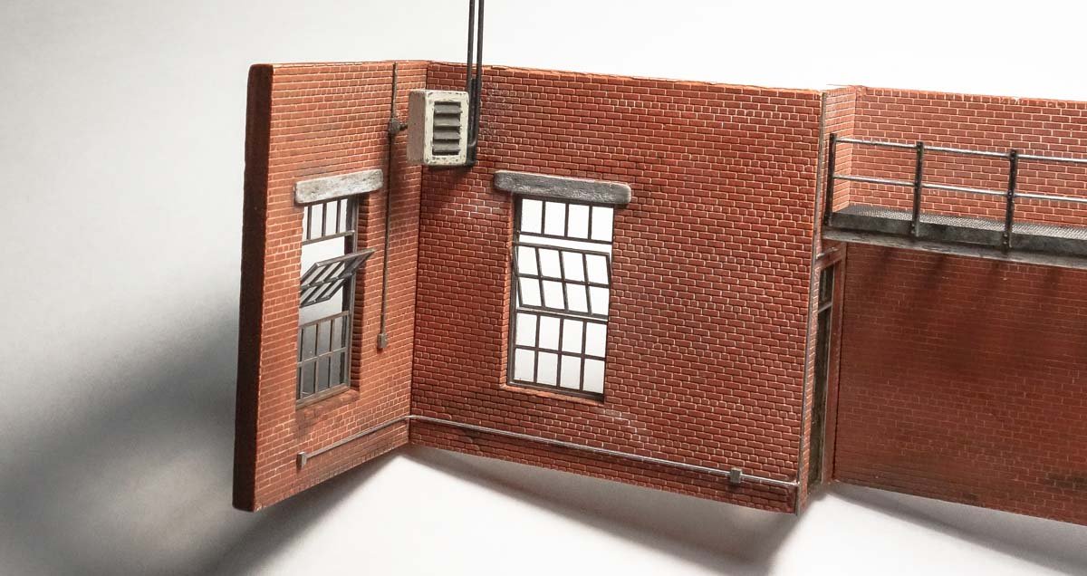
Thank you O.C. and Popeye for the nice comments - I appreciate it. And thanks to all for looking in and for the likes. That's nothing Keith, look at their coveralls. A little honest dirt never hurt anyone. Thank you Mark and Egilman. More eyes and constructive criticism is always appreciated and welcomed as it invariably results in a better model. Yes you right, it is too light and clean looking and needs additional attention. I'll wait until I get the lighting in to see how much darker it needs to go. Hello Lou, thanks for the comment. I agree that service pits were commonplace and even iconic in repair shops of yesteryear, but as you say they have been mostly replaced with lifts. Which is good because today, many jurisdictions have banned pits altogether citing fume accumulation (one of several concerns) as a danger to workers health and the potential for ignition. In fact, the National Electrical Code considers them a hazardous location requiring an explosionproof wiring system (to prevent ignition) for light and ventilation. Something I've found curious looking through old photos is the scarcity of pits and instead this method of working the underside. Based on the abundance of images like this, it must have been a very common way to work on these old rather light vehicles. But it is timely that you mentioned service pits - please read on. . . Backtracking - Adding a Service Pit One of the things I like best about modeling these small dioramas is that there is no specific prototype - only what's in my head. So there is no set design that I must adhere to or elements that I must include. Starting out, I always think I know how it will end, but rarely do my initial plans go unchanged. I had intended to have several vehicles all pointing forward, side by side with one vehicle displayed in profile in front of the work bench. Shop equipment would be placed around the wall perimeter. It occurred to me that this arrangement is rather dull, visually uninteresting and there is something about it I just don't like. I believe dioramas need to have a central focus, something prominent that your eye is drawn to - something my model doesn't have. Looking through my collection of old photos, I found this one of a wheel alignment/service pit and decided this element could be a great main focus for my dio. The image is from one of the collections at the Library of Congress, but I don't remember which one. There are a number of things that drew me to it. One is that the pit itself is irregular in shape and there is working room around the vehicle, not just a narrow pit down the center. The pit has two depth levels; the outer shallower level and a deeper drivetrain pit, so it will add dimension to the model. Also, the iron structure of the platform is an eye draw and I think it will nicely display the vehicle standing on it in profile – or so I hope. And I have just enough room in the shadow box case to drop it down through the floor. So I drew up a pit that will fit the space I have. The general dimensions and depths were taken from modern truck wheel alignment pits. One of the wheel rails is movable in or out to accommodate vehicles of different widths. As you can see below, the pit eats up a lot of real estate, but I think the scene will feel less crowded because of it. It is made from sheet styrene; .040” for the floor and .020” for the walls. 1-2-3 blocks were used to keeps things square and true in its assembly. Modifications to the existing model were necessary to accommodate the pit. First, the electrical piping was removed and then the mezzanine was shortened because the new side door is quite wide and would run into it. Also, the ladder for the mezzanine will be pushed back to the rear wall whereas originally it was going to be free standing up front. Three feet were cut from from the structure and the free hanging end was braced. The mezzanine will also have support from hanging ceiling tie rods when the time comes. The side window was removed and the opening enlarged to a height of 12 feet by 10 feet wide for the doorway. The floor was cut out and the pit was test fit. The double door is wood and opens outward, so the hinges and locking hardware would be on the outside. A drew up a door and used it as a construction template. The basswood strips were colored beforehand with India ink/alcohol and topped with a green acrylic mixture, some of which was pulled off with cellophane tape. The boards are glued directly to the template with PVA and the frame work is glued on top of that – then trimmed with a straight edge and scalpel. Using the drawing tick marks as a guide, holes for the exterior strap hinge bolts are drilled clear through the material and injection molded washer/bolts are inserted. The bolt shanks are trimmed flush on the back side of the template. A touch of thin CA is applied to the ends of the trimmed shanks where capillary action draws it into the hole leaving the front side clean of glue. A security bar is added. The brackets are made from aluminum beverage can sidewall. I drilled small shallow divots into the brackets to mimic attachment screw heads, but they're barely visible. Also, I ran a black permanent marker down the back side of the template where the two door sections meet so that the white paper doesn't show through. The door header is a styrene “I” beam with one side sanded off and it scales to about 9” wide by 12.5' long. Flat black enamel was applied with a cosmetic sponge to add a little texture followed by pigment powder to add a hint of rust. Styrene bolt heads were placed and pencil graphite was rubbed on to highlight beam edges. Basswood door jambs and side casings were glued into the opening. The header was glued on and the wall opening was backed with a piece of sheet wood as a place to land the door itself. The ladder for the mezzanine is basswood with brass rungs. The brass is .014” dia. and the rails are scale 2” x 4”. The two rails are taped together and the rung holes are drilled through both at the same time. Short pieces (about 1”) of the pre-blackened brass are inserted through the holes and the rails are then pulled apart until the desired width of ladder is reached. This leaves all the brass rungs jaggedly sticking out both rails which are now trimmed flush and end glued with thin CA. The rails are stained and styrene stand-off brackets attached. The styrene pit was primed with an air brush followed by a couple of shades of gray acrylic on top. This is not the final coloring, just a base. The pit was glued into place and styrene angle fitted around the perimeter. Enough with backtracking - it's time to move forward again. Thanks for taking a look. Gary
- 189 replies
-
- 29
-

-

-
Love all your various blocks Keith - they turned out very nice. I like the way your rigged block looks, even in the greatly magnified photo above. A shackle at .05" is crazy small and in my unasked for opinion, I just don't believe it's worth the effort to create something (300 times) which in the end will only detract from the overall look and feel of the model just to say the detail is there. Usually when I model something that looks like a "twisted dead gnat" (made me laugh out loud) - I leave it out. It's a scale representation 120 times smaller than the prototype and many details must of course be left off. Very nice progress Keith. Gary
-
She's looking beautiful Chris - nice job. Really like that deep blue. She's going to be a pleasure to paddle. Gary
-
Just catching up OC and I see you’re progressing nicely. The figures are terrific as expected and that extra face shading really makes a difference. At your level of detailed perfection, it does not surprise me that you can only complete 6-8 per week. After all the problems with the glass case(s) it must feel good to finally be in possession of an undamaged display case. I think switching to acrylic was a good choice and I look forward to watching the building of the structures and scenery. Gary
-
15' Dinghy by Bedford - FINISHED - 1:1 scale
FriedClams replied to Bedford's topic in Non-ship/categorised builds
Wonderful work on the oar rest Steve - elegant and utilitarian at the same time. And the boat itself is expertly crafted and simply beautiful. I love it. I remember seeing it when I was following your 1:8 model build of it (also stunning.) There is something so appealing and even nostalgic about a small lapstrake boat. Gary -
Hello Chris - very nice progress on Sassafras. Looks like first launch is not far off. I want to chime in on the tie down issue. I don't proclaim to be an expert on canoes and kayaks, but I have owned and transported quite a few of them. I don't believe any of the hardware shown in post #182 is adequate as roof top tie-down points. A heavy gust of wind or the first time a tractor trailer rig blows past at 70 MPH and I would expect them to be torn off or broken off. Wrapping web straps around thwarts up close to the breast hooks at both ends is a better option. As @Bedford has stated, the craft needs to be kept from sliding forward during emergency braking. And you also want to keep it on the roof during strong winds. I always strap completely over the craft with ratchet straps in addition to the positioning attachments. I think of my canoe as a narrow parachute whenever I lash it to a vehicle. Typically you will not find any hooks or cleats on canoes/kayaks, especially above the gunwales. Unlike small open boats, canoes are expected to be flipped and metal protrusions are a liability and just something to get hooked on or clothes/line to get tangled in. Especially important if you end up on a stream or river. Not trying to lecture here Chris – just my two-cents worth. She looking sweet. Have fun. Gary
-
Just found your log Andrew and I really like the way your model is progressing. Beautiful work - so clean and precise. I'll be watching for future installments. Gary
-
Just read through your log FF and very much enjoyed it. Nice work on the hull and a great job scratching the engine - I like it. Your model has a wonderful authentic feel to it. Look forward to future updates. Gary
-
Good to see you starting another project Patrick. I will be following your progress. Best of luck with the new build. Gary
-
Simply beautiful Siggi ! Perhaps a 60 gun ship shouldn’t be referred to as pretty, but she is. Gary
-
Beautiful job Eric, longship and base. I agree with Brian and Steven that the rustic base is a nice compliment to the model. I really like the tones of the two woods together and the way the walnut stands proud of the cherry is a great visual plus. And the chatter marks echo the thwarts. Very nice work. Gary
-
Four more to go - put your head down and slog your way through. Really nice work on the jackstay Keith and such a fine detail ! Gary
-
I'll be taking a seat in the back to watch your dual chopper builds Egilman. I appreciate the extra effort you've taken in presenting the historical story of these craft. I'm always amazed that these birds can actually fly when I stop and consider the remarkable physics and mechanics behind them. Like huge metallic dragonflies. Good luck with both. Gary
-
Ouch ! But a very nice recovery Druxey. Yes, but I don’t see how you could have anticipated the difficulties beforehand. Sometimes a thing just needs to be tried. I have no doubt she will be an absolute beauty in the end. Gary
- 433 replies
-
- 7
-
-
- open boat
- small boat
- (and 1 more)
-
Those new figures have really crisp details and your painting is top notch. I have never tried either Vallejo or Mig products, but they sure produce some nice results don’t they. Of course that is mostly due to the person holding the brush. You have a steady hand OC. And I agree with the others, that placing the farm at an angle has greater visual interest and appeal. Gary
-
Beautifully done Gary - she looks great! Congratulations on the completion of this very handsome model. Gary
-
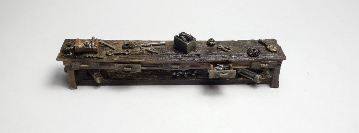
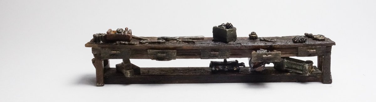
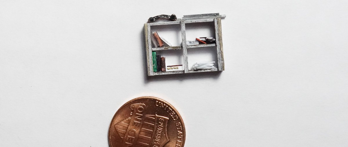
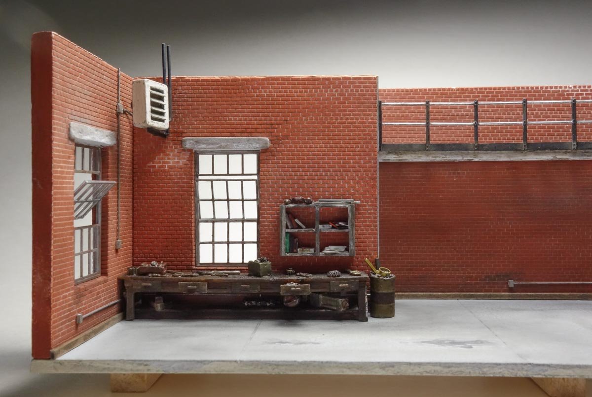
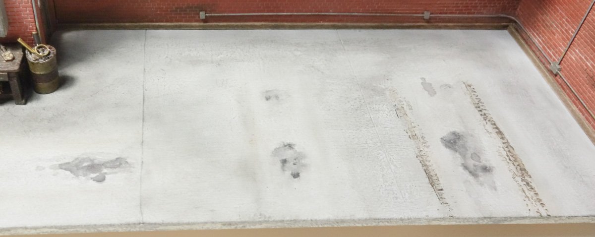
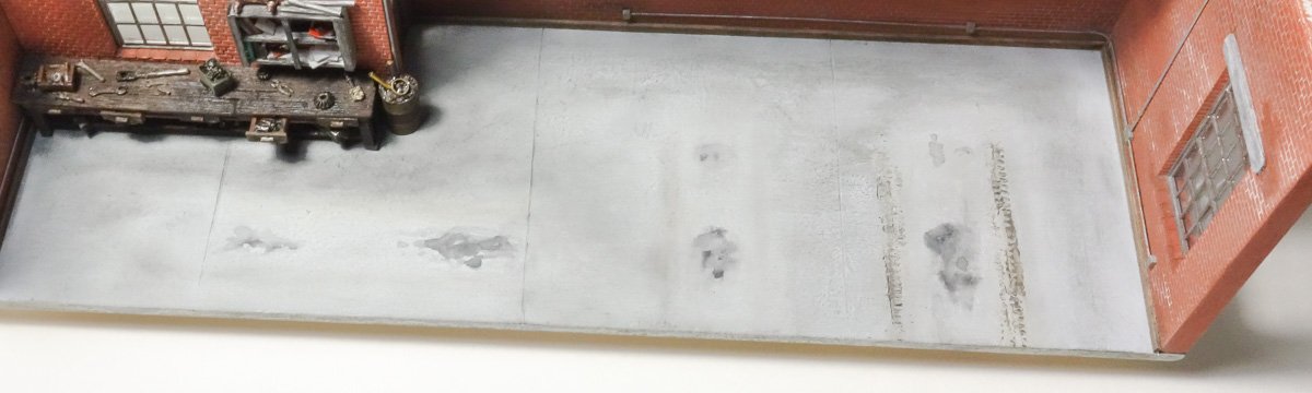
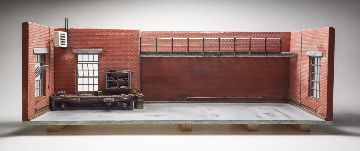
Hello and thanks to all for the nice comments and for your past experiences with space heaters. When I was a young man I worked for a year as an electrician in a welding fabrication shop that was located in an old run-down mill building. That winter was freezing cold and it seemed colder inside that cavernous old structure than it did outside. But I can still remember how good it felt when those darned heaters would kick on and wash you in warmth - if only temporarily. Hello Popeye - thanks for the interest and fine comment. It will have a small compressor for tires but no air tools. In this time period (1920s to 40s) pneumatic tools were not yet widely used by mechanics - as far as I can tell. I just haven't seen them in historic photos, so I'll play it safe and keep them out. And thanks to everyone for the likes and for stopping in to take a look. A Floor and a Workbench. A small update. There will be more than one workbench in this shop, but here is the first one. The bench is put together from a number of materials. The top is a section off an old resin casting I had in my junk box that I cut down and then modified further. The frame and bottom is basswood and the items on the lower shelf are nondescript chunks of white-metal and styrene. It is brush painted in enamels and oil paint. There is nothing like black oil paint to make a thing look good and greasy. A wall mount book case of basswood is 5/8” wide by 1/2” tall. The books and papers/pamphlets are bits of styrene colored with permanent markers. The 35 gallon trash barrel is a solid white-metal piece. I drilled a hollow into the top and placed debris in it. Someone needs to dump the thing. All glued into position. The floor is 3/32” basswood. To simulate concrete, it is painted with gray craft acrylic and allowed to dry. PVA is then mixed with a couple drops of paint and brushed on all over – rather thick. Before it completely dried I jabbed at it with a cosmetic sponge to give it some texture and unevenness. The surface was then lightly sanded and a few concrete relief cuts were added. Oil drips are replicated with India ink mixed with water and the walking patterns and other general smudging is added with pigment powders. Scale tires with an aggressive tread were rolled through brown acrylic and transferred to the floor. Finally, a scale 6” base shoe is added to all walls. Thanks and stay well. Gary

- 189 replies
-
- 24
-
-
Nice update Brian. Extremely clean and well executed work as we have all come to expect. It is reassuring to know that I am not alone in this. I have modeled myself into a corner more than once. And aren't 1-2-3 blocks the handiest things? Gary
-
Ancient Mongolian Ox Cart by Bill Hudson
FriedClams replied to Bill Hudson's topic in Completed non-ship models
An interesting build Bill and so nicely executed. Gary -
Wonderful work Druxey and a very helpful tutorial. I must try your cellophane tape method as it seems perfectly suited to small models. Thanks for sharing your techniques. Gary
- 433 replies
-
- 3
-
-
- open boat
- small boat
- (and 1 more)
-
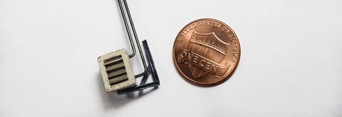
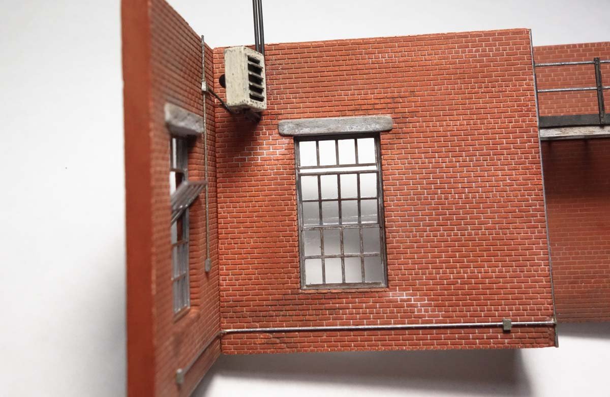
Thanks for visiting and for the the "likes". Space heater I wanted to show some method of heating the shop and there is a spot in the upper left corner of the diorama where I could place a hydronic space heater. Many old photos of repair garages show radiators hung on the walls as in this cropped 1929 image from the National Photo Co. Collection – Library of Congress. These radiators would be difficult to scratch in this scale and I didn't want to use up too much wall space, so I made up the unit below. It is entirely styrene except for the steam/water pipes coming out the side, which is blackened brass. It was brush painted in enamels and roughed up a bit. I glued it to the wall and ran conduit down to a switch for the fan. The roundish blob on the back of the unit is the fan motor and it connects to a junction box via a piece of solder. This post brings the log up to date with the model in real time. Thanks for stopping by. Stay well. Gary
- 189 replies
-
- 23
-
-
-
I've been reading your log O.C. and I'm very impressed with your miniature painting ability - very nice indeed. I look forward to seeing how this all comes together (assuming of course someone can deliver your replacement case as a single intact piece.) This is an ambitious and very cool project. Gary

