
HOLIDAY DONATION DRIVE - SUPPORT MSW - DO YOUR PART TO KEEP THIS GREAT FORUM GOING! (Only 51 donations so far out of 49,000 members - C'mon guys!)
×


FriedClams
-
Posts
1,368 -
Joined
-
Last visited
Content Type
Profiles
Forums
Gallery
Events
Everything posted by FriedClams
-
 Been reading through your log Chris and you're doing a great job. I've never tried stitch & glue but it produces a really nice result. It's coming together very nicely. It has been said that the amount of enjoyment a boat provides is inversely proportional to its size. I believe that statement to be true as there is no craft more enjoyable than a solo canoe. About 25 years ago, I built a 14' solo stripper from plans I found in the back of a Wooden Boat magazine. It was made of Western Red Cedar, glass cloth and polyester resin. It looks decent enough in the photo, but close inspection reveals the hand of an inexperienced builder. But it floated and could take a beating. Because it weighed so little (like all solo canoes), it could be carried down trails even over difficult terrain back to quiet and secluded waters. Ponds of a couple hundred acres, alive with waterfowl, beavers and dragonflies and where the backwaters are a tangled mess of dead-fall and primordial mud. No motorized craft, no cabins, no other people and no noise. Wonderful. I don't have that canoe anymore and I sure miss it. Reading your log gives me the itch to build another one (minus the mistakes I made on the first one.) Sassafras is looking terrific Chris and I'm sure you are going to love paddling your local waters. If you're new to canoeing, developing strong and efficient paddling skills is important even if you decide to avoid fast rivers. Strong winds blowing across flat water can be a challenge for even the strongest paddlers. And my experience has been that wind develops unexpectedly and will always blow you back away from your take out point. Bring a dry-bag with a change of clothes. And Deet. Look forward to seeing the completed craft. Have fun. Gary
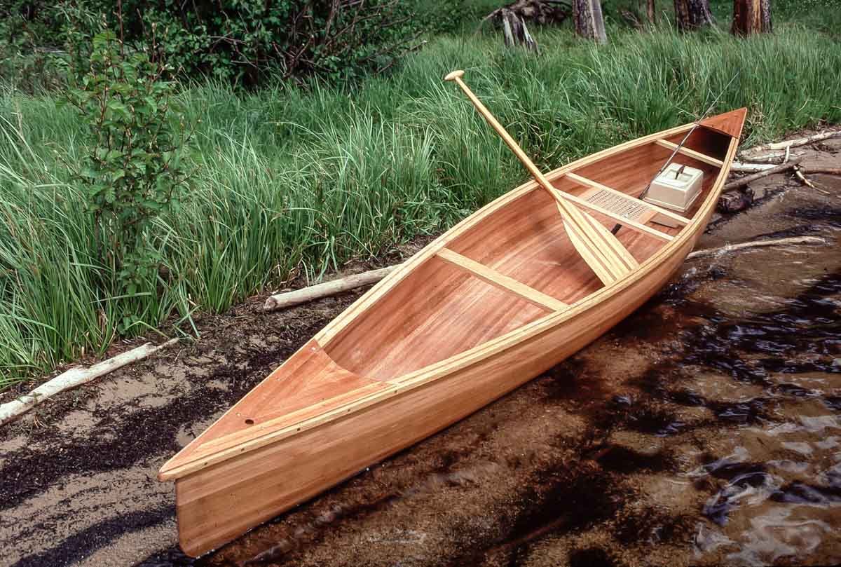
- 299 replies
-
- 11
-

-
Just catching up Vaddoc and I see you are progressing nicely. Very meticulous and careful work. Excellent. Gary
-
Good to see you back posting again Michael! I have always admired your work be it boat, loco, etc. Look forward to updates on your projects. Gary
-
Just catching up Keith and you've made some fine progress. I admire your attention to details, like removing links one-by-one to achieve symmetrical swag for the rudder chains. Like Wefalck stated "a thing well-done needs time". Nicely done Keith and looking good. Gary
-
You're off to a great start Jean-Paul. I have no doubt this model will turn out wonderfully. I've pulled up a chair. Gary
-
Superb work Ekis - I love it! Gary
-
Extremely nice work Dan! I find the water/waves very convincing and of course the vessel itself is great and has a wonderful authentic feel. Congratulations on its completion. Gary
- 33 replies
-
- 2
-
-
- James B Colgate
- whaleback
- (and 2 more)
-
Superb work as always Johann. Gary
-
Much nicer Keith - a great improvement. It now indeed looks symmetrical, clean and orderly. Gary
-
Wonderful work Jean-Paul - this model turned out beautifully! Congratulations on its completion. Gary
- 164 replies
-
- 1
-
-
- first build
- model shipways
- (and 2 more)
-
How true. When I have a brain fart, I usually correct the mistake quickly and then set the model aside and out of my sight. Otherwise, the error just stews and I resist returning to the model. But I always do. Take a breather and enjoy your beverage Mark. Gary
-
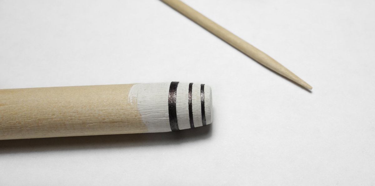
Keith, you are selling yourself way short. I truly enjoy watching you work through modeling challenges and solving problems. Your log and methods are a great contribution individually and to the whole of what can be learned here at MSW. I personally like the casks you made – nice and crisp and they look good on the deck. On post #176 you welcomed other approaches, so here is how I would go about it. I would use paper for the banding. On small stuff like this I always use the sticky edge of a Post-it note. I stick the note onto the cutting mat, mark it and then slice off the width that I need with a scalpel. When slicing off 1/64th of an inch of paper it helps to not have the paper move while you're cutting it and that is one reason I use a Post-it note. I then run a black permanent marker down the length of the strip before I peel it from the cutting mat. The second and more important reason I use a Post-it note is that it helps in placing the band on the cask. I place a minuscule dab of CA on one end, attach it to the barrel/cask, let dry and then wrap the band around the barrel. The tackiness of the paper keeps the band from slipping toward the narrow end and it also allows me to lift the band or nudge it sideways for better positioning. Another small dab of CA secures the opposite end and a scalpel trims the length. Once I'm happy with the look, I brush on a very thinned out PVA/water mix (like milk) and the banding isn't going anywhere. Wefalck is correct of course stating that banding around a conical object is not a straight strip but rather a mild arc, but on something this small and a strip so narrow, you can get away with it. On larger scales, automotive pin striping material works nicely. Here it is, yet another way to do it. It's roughly made to Keith Aug's dimensions. Your model is looking sharp Keith – keep at it. Like the chest too. Gary
-
I bet that took a while! And it’s a great eye catching detail. She is progressing very nicely Keith. Excellent work! Gary
-
Excellent workmanship Brian and a wonderful result. Your model is looking fabulous. Gary
-
Beautiful work on those anchors. As said many times before yet worth repeating - extraordinary detail at this scale. Excellent. Gary
-
Hello Dan, Great to see you starting a new project. This is a very interesting vessel and logically its design and the theory behind it makes perfect sense to me. It will be interesting to watch it take shape. Gary
- 33 replies
-
- 4
-
-
- James B Colgate
- whaleback
- (and 2 more)
-
Catching up on your schooner Allen and she's looking very nice indeed! The rigging looks terrific. I too have never had much luck with stainless cable when applied to smaller scales, because so much force is required to keep them tensioned on a model that moves around with humidity. As others have stated, you are moving fast, but the workmanship has not suffered in the least because of it. Beautiful work. Gary
-
Such a wonderful log Keith, so fun and educational to read. I love the ships bell, but making even the liferaft clamshells look good - well that's just modeling mojo. Terrific work. Gary
-
Hey Eric, I’m sorry to hear of your loss. Loosing someone so close is always such a difficult time. I wish you and your family peace. Gary
