HOLIDAY DONATION DRIVE - SUPPORT MSW - DO YOUR PART TO KEEP THIS GREAT FORUM GOING! (Only 51 donations so far out of 49,000 members - C'mon guys!)
×


FriedClams
-
Posts
1,368 -
Joined
-
Last visited
Content Type
Profiles
Forums
Gallery
Events
Everything posted by FriedClams
-
 This boat is coming along great G.L. Good idea using a wallpaper steamer for the steam box. The framing and grating turned out sweet - very nice. And I enjoy the detailed description of your work process - thanks. Gary
 -
Wonderful work Valeriy. I am always impressed by your splendid metal work. The wheelhouse and its details are very nice indeed. I’m looking forward to seeing how your brackets will be used. Gary
-
Catching up on your build Keith and enjoying observing your progress. As usual your work is well thought out and immaculately executed. Thanks for sharing your work process in detail. Gary
-
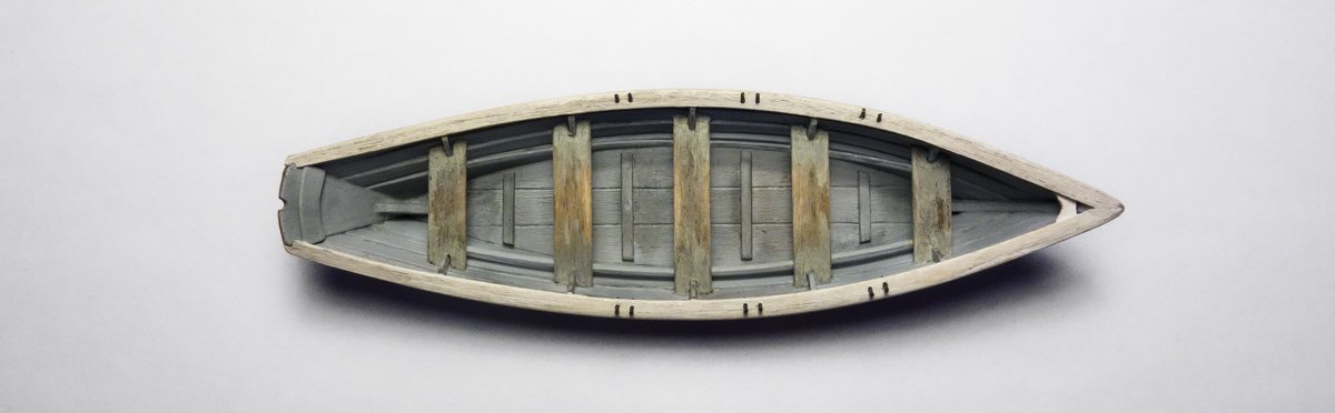
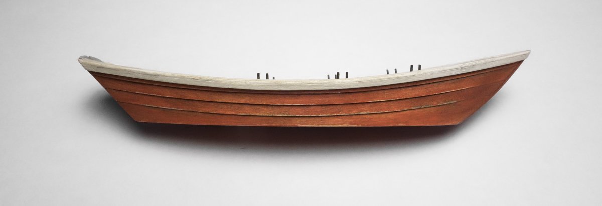
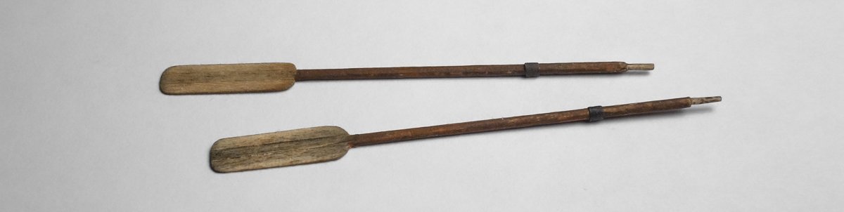
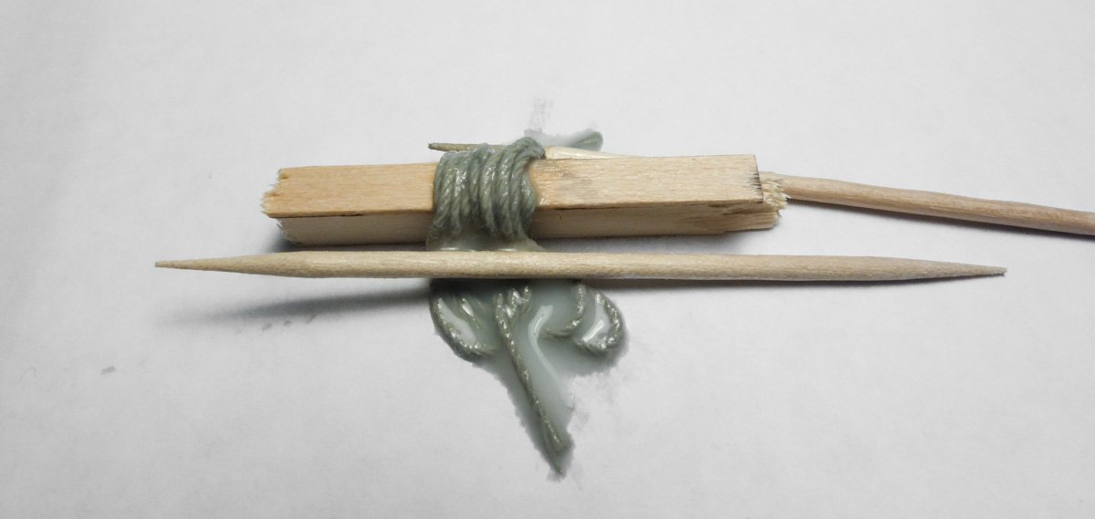
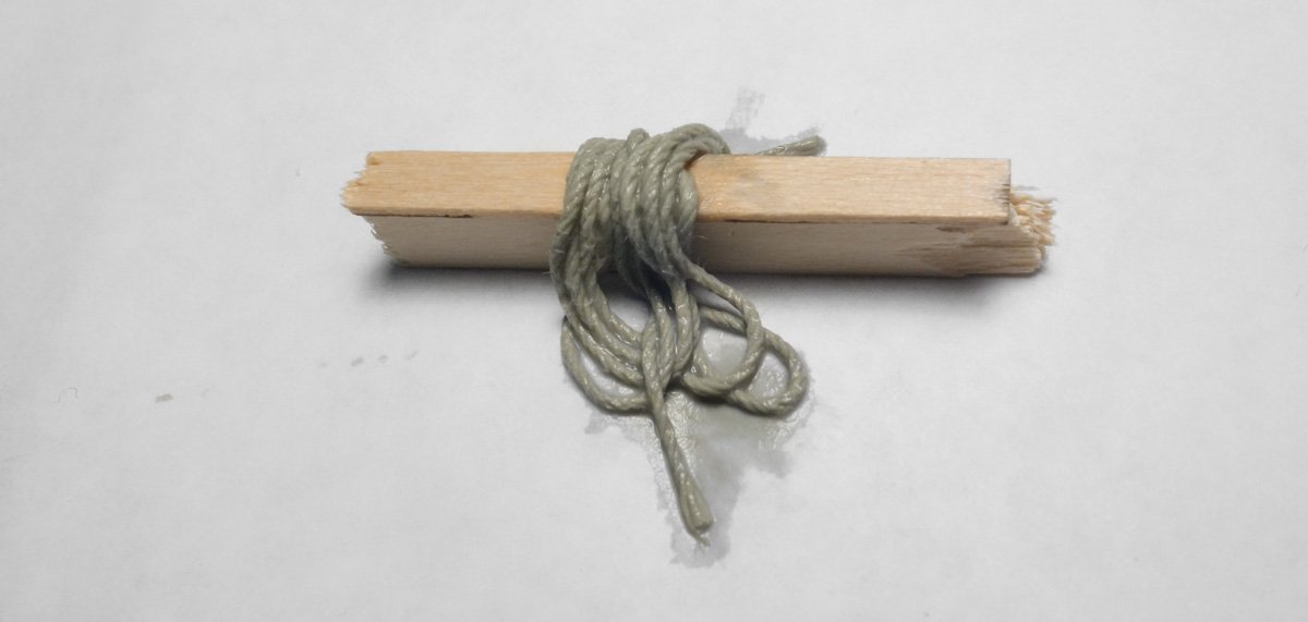
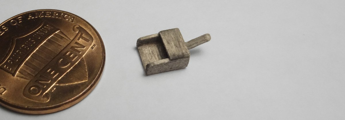
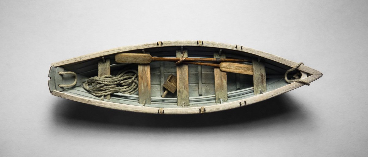
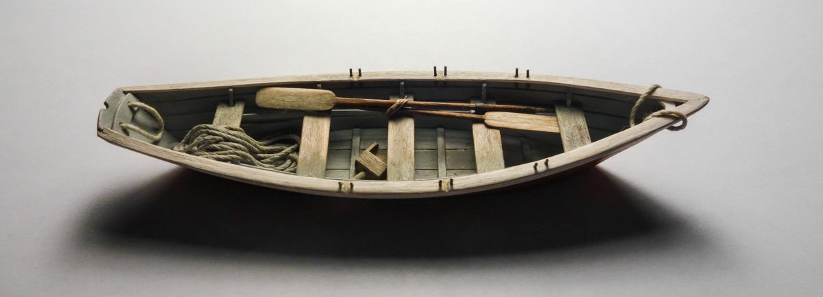
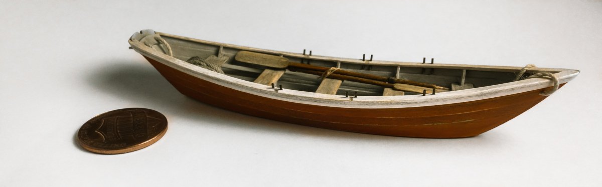
Thank you Vaddoc for the comment and kind words - I appreciate it. And thanks to all for stopping in and hitting the like button. Finishing up the lifeboat dory. It has been close to a month since my last post and yet I've accomplished little in that time. As you all know, sometimes life just gets in the way of hobbies. But to bring things up to date, I have finished my lifeboat dory although it is not yet mounted onto the wheelhouse. The boat shown in this posting is actually not the one I built in my previous post. I decided to build a second one to correct what I feel is a sort of heavy clumsiness in the first effort. This only became noticeable to me as I began to add color to it - and once I saw it, I couldn't un-see it. This second boat was built exactly as the first, only this time with wood sanded down to finer dimensions beforehand. So the resulting boat is a little more delicately made. Once that was done, I began the coloring process by ageing the entire boat with a very light brown/umber chalk and alcohol wash. The interior of the boat was then brush painted with a sky gray acrylic. The thwarts were painted the same gray with a touch of raw umber added to set them apart from the rest of the interior. The gunwales and caps are an off-white acrylic and sanded for wear. The thwarts were scraped revealing the aged wood beneath. And finally, dry chalk was scrubbed on here and there. The hull exterior was painted with a thinned mixture of orange and burnt umber acrylic. It was then lightly sanded. Pieces of basswood were filed, sanded and assembled into a set of oars. A wooden baler was made up. This boat will have a coil of rope thrown over the rear thwart. In order to get the rope to drape naturally, I make a mock-up and place some soupy wet string over it. The soup is “wet" water with color and glue added to it. Wet water is simply water with a surface tension reducer added so it flows and penetrates more easily. Years ago when film-developing shops were common place, I used a darkroom print making chemical called Kodak Photo-Flo for this. In the days of digital, Photo-Flo isn’t as easy to find and I now use a dishwashing machine rinse agent like JetDry instead. A quarter teaspoon per quart of water and that will last – a very long time. If you don't mind a few suds, liquid soap or windshield fluid is also commonly used. I add a speck of gray acrylic and raw umber to a spoonful of the wet water as a colorant and a drop of PVA to firm things up when dry - not so much PVA that it turns into rock and can’t be removed from the mock-up, just enough to hold its shape. I leave it in a puddle like this for a few minutes to give it time to fully penetrate, and then absorb it away with a point of paper towel. The color changes once the excess liquid is removed and the natural color of the string blends with the applied color. This process works best on cheap white/yellow string. High quality miniature rope tends to resist being colored in this way. Beckets at bow and stern have been added and everything is placed in the boat. I could have stuffed lifejackets under the thwarts but I didn’t want to add bright colors to the mix. Maybe some sort of fresh water container and another set of oars would be appropriate, but I like the visual balance of what is there now and I am a strong believer in the “sometimes less is more" philosophy. Thanks for stopping by. Gary
- 424 replies
-
- 31
-

-
Thank you Keith - I appreciate your comment. Thanks for compliment John. Yes, it will have some wear on it, but less than the dragger itself. This boat could have replaced the original one and as such doesn't need to echo the same level of crustiness. But I don't want it to look out of place either. It's just an illusion Jim. I try to show in my log what has mostly worked for me, hoping others might find it useful or interesting. There is really nothing instructive in all my throwaways, so I don't share them. My work process is rarely smooth and easy, but I'm pleased that it comes off that way. Thanks for your nice comments Jim. Hello Druxey and thanks for the comment. This method worked out okay on this small hull, but I've had problems applying it to larger models. The force needed to keep the keel/stem in place on the jig necessitates too many strings/threads to the point where you ask yourself - why am I doing it this way? Thanks for swinging by. Gary
-
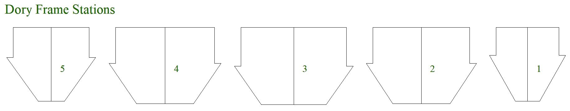
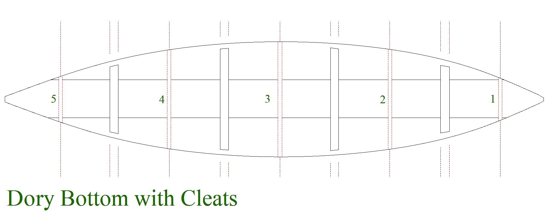
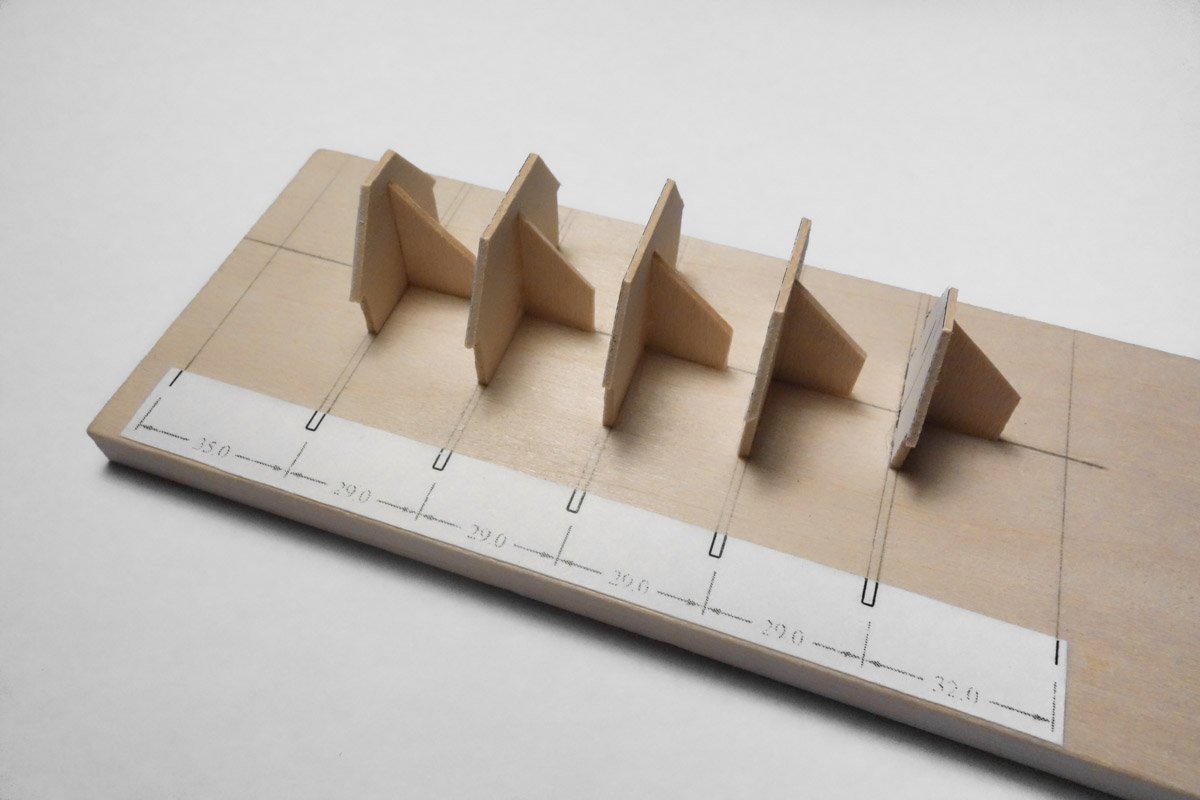
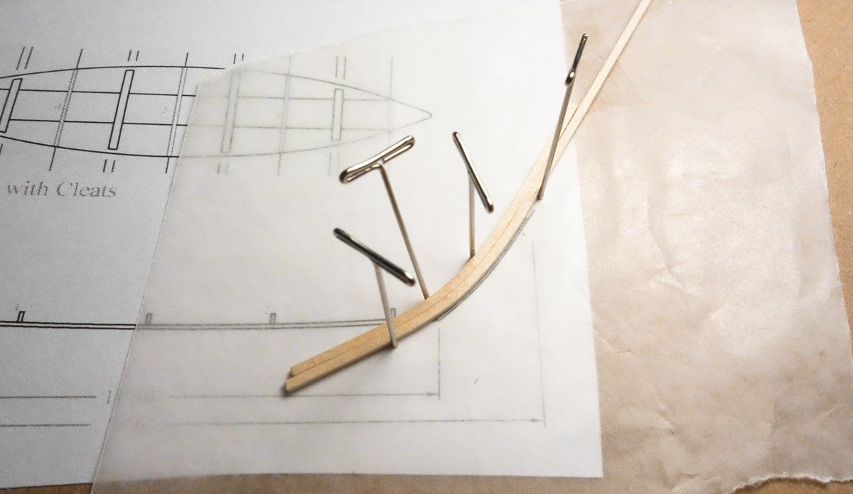
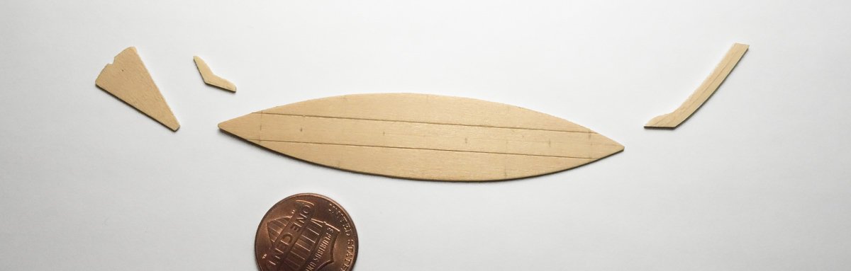
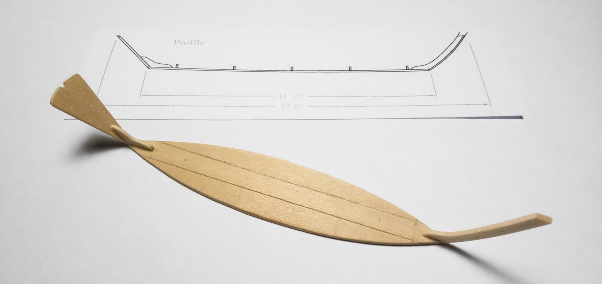
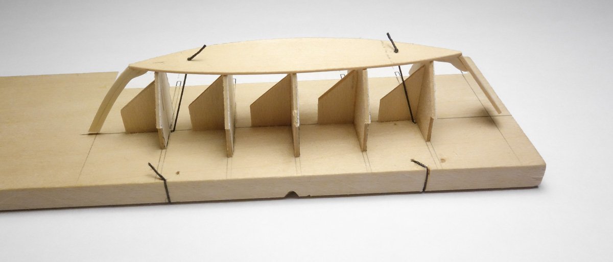
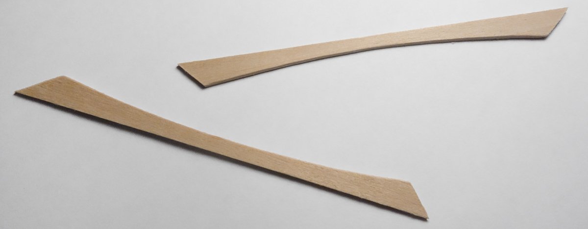
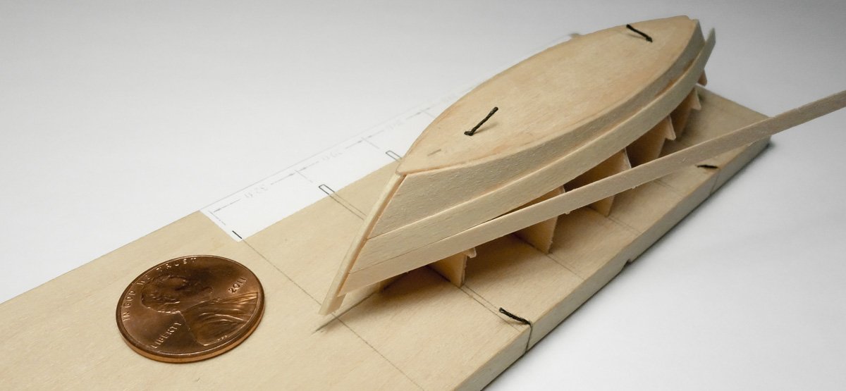
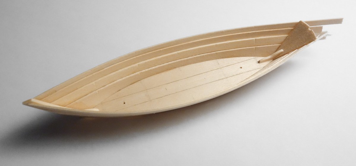
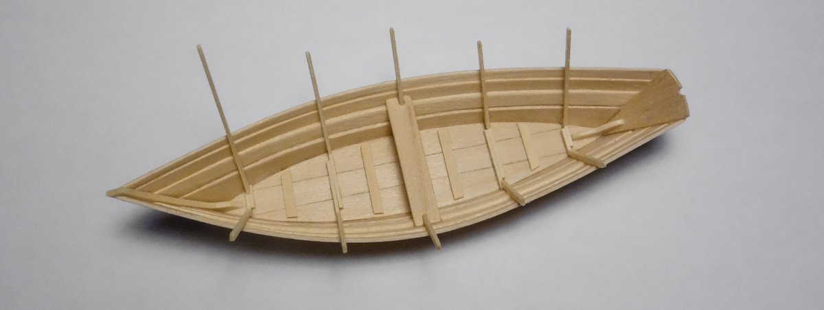
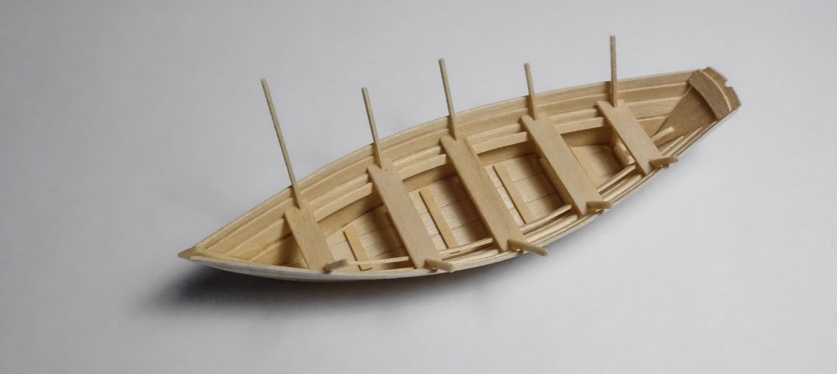
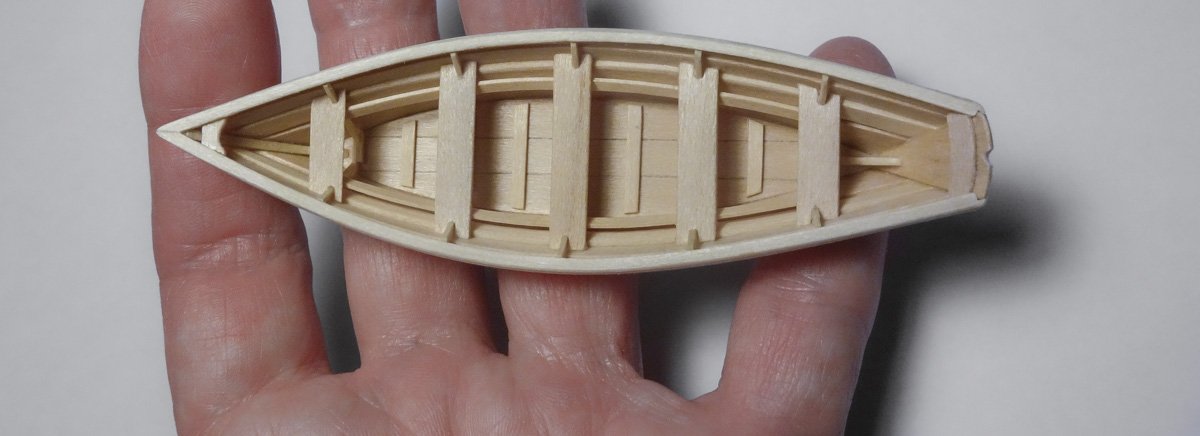
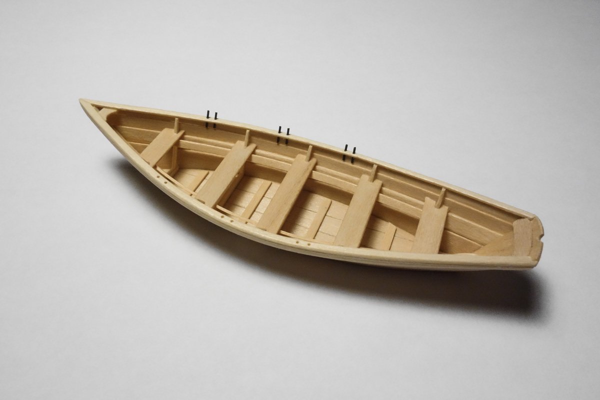
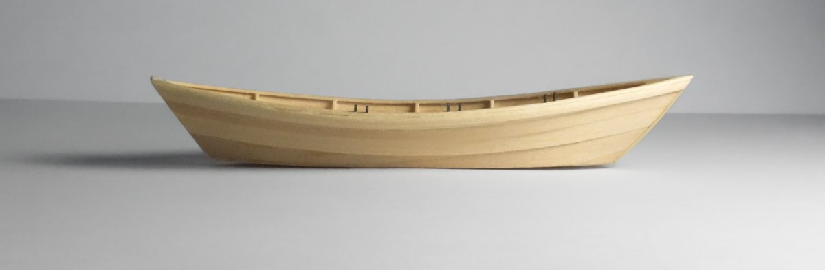
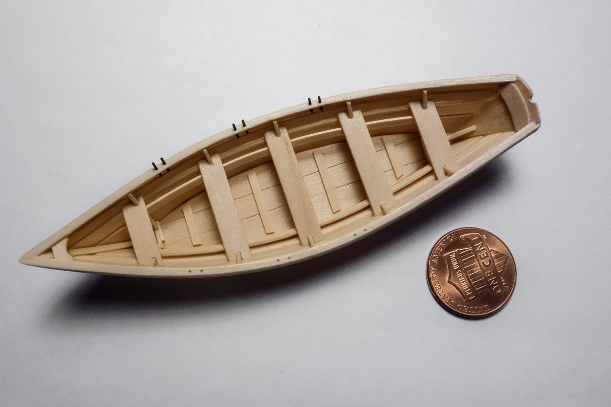
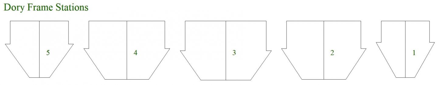
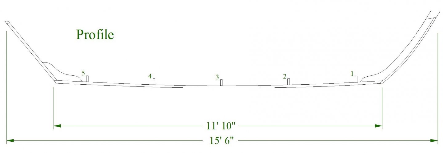
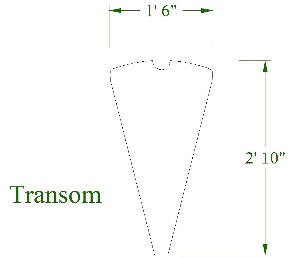
Thanks to all for stopping by and for hitting the like button. Lifeboat This dory is 15’6” LOA, which translates to just under 4” in 1:48. I begin by cutting out the frame stations and mounting them to a build board. The stem is made from two thin pieces of basswood laminated together. They were first soaked in alcohol, then pre-bent and finally glued and formed over a template. The lamination eliminated the problem of kinks in the bend and the line of contact acted as a rabbet line in landing the strakes. The transom, stern knee and bottom planks are made and sanded. The bottom is cut from 1/32” sheet stock as a single piece. It is scored to imitate individual planks, then marked for frame and cleat positions. The four pieces are assembled. The bottom/stem/transom is flipped onto the frame stations, aligned and pulled down tight with thread. The holes where the threads pass through the bottom are located where bottom cleats will eventually cover them. No glue is used in placing the bottom. Next the garboards are cut. The plans provide the shape of the garboards – hallelujah! There are four planks per side to go on. The garboards (as always) are the most trying to place. The most difficult aspect of this little boat was simply its size and fragility. A number of times I had to fight back the urge of returning to childhood and smashing the thing to smithereens. After walking away a time or two, I got the garboards on by placing them simultaneously, working my way back from the stem and edge gluing them to the bottom planks as I went. This kept the stem and transom straight and it also kept the bottom centered over the frames. Both edges of all strakes are beveled and are set to provide for a slight overlapping edge - not a full lapstrake. Here is the hull fresh off the form. Because I did not pre-bend the strakes the hull tries to straighten out and in this photo looks more like canoe than a dory. Putting in the first thwart opened up the beam back to where it should be. The floor cleats are glued in and the crossed futtock frames are placed piece by piece. The seat risers go in and the remaining thwarts. The stern cleat is placed. The gunwales and caps go on and finally the breast hook. Thole pin holes are drilled and the starboard side pins are temporarily placed to see how they look. The pins are 0.02" phosphor bronze. They will be pulled before paint is applied. And that’s that. In the next post the dory gets some color, oars, a baler, becket and whatever else comes to mind. Thanks for taking a look. Gary
- 424 replies
-
- 28
-
-
Nice looking kit and a very interesting vessel. I look forward to watching your progress. Gary
-
You’re off to great start on this beautiful yacht Jim. The extra care that you’ve taken in the fairing and lining off process is always a good investment. She’s looking good! Gary
-
Good to see you back at Germania Keith. I like that you're sourcing old doors for the decking material. When I think of modelers from centuries past, I envision men rooting around in the wood pile for whatever they can find that could be put to use. There is something satisfying about reusing the old for the new. It gives the model an added story and history. And your drum sander looks sophisticated enough to me. Gary
-
You're moving along quickly on this model Nils and it is looking sweet. Your engine and fuel tank turned out great as well as the wooden enclosure surrounding it. Very nice. Gary
-
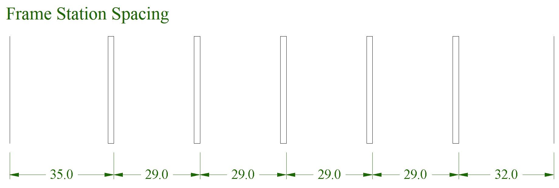
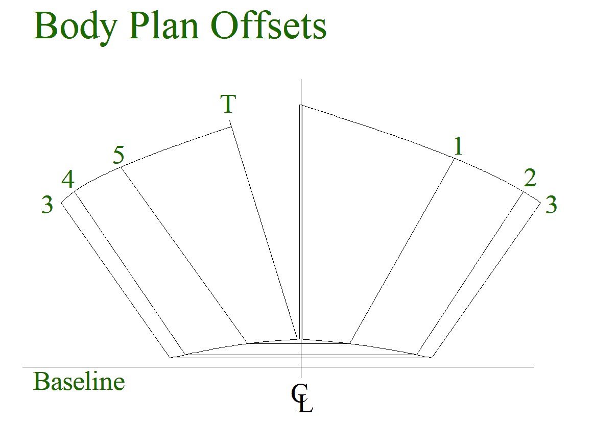
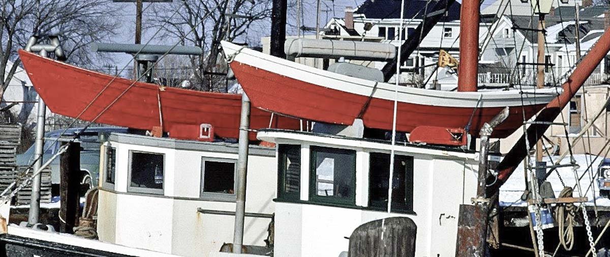
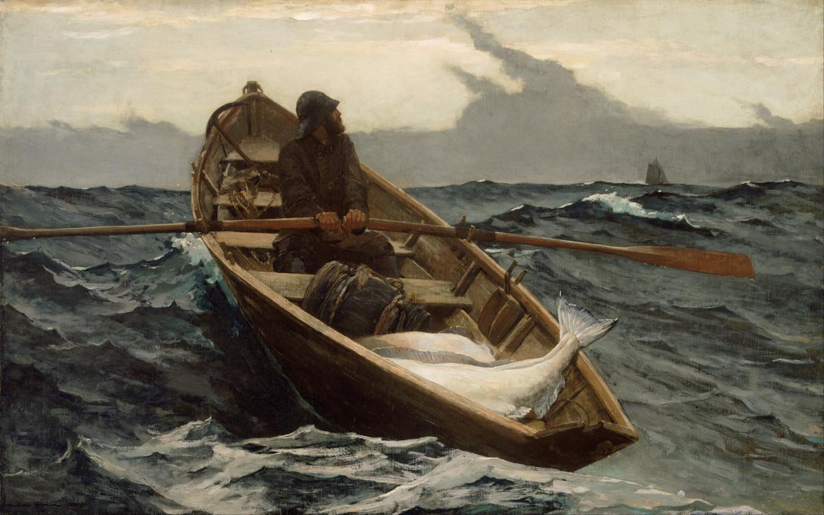
Thanks John - glad you stopped by. Thanks for the kind words Druxey. The solder is a great material for this sort of thing - soft, flexible, doesn't kink and it's available in a many diameters. Thanks for looking in and for the comments Gary. I'm happy with the way the valve turned out, but I threw out three other attempts before it. I'm still not willing to admit how much time I spent on it, but the word absurd quickly comes to mind. There's probably a entire roll of electrical tape wrapped around it in various places, it's just difficult to see. Thanks Keith. Hello Wefalch. Thanks for stopping by and for the nice compliment. It is interesting that you mention the 1970s as the time period when the lamp-board coloration changed, because that is what I noticed when reviewing photos of these boats. My evidence was anecdotal at best so I made no mention of it. Yes, I am aware of Marcels' exceptional work though I didn't realize he had his own web page. I have learned most of what I know about weathering from modelers like him and the model railroad folks in general. Hello Keith - glad to have you looking in. I first saw the use of solder in modeling a few years ago by a guy that had used it as a tire inflation air hose on a 1:48 service station diorama. Colored orange/brown, he had it strewn across the ground and over objects in such a natural way, that I just had to try it for myself. I now use it when ever I can. Here is a little preliminary CAD work and info on the rooftop dory. The lifeboat of choice for these small draggers seems to have been the classic Banks Dory. These dories were sturdy little boats and very stable even under heavy loads. They could also handle some pretty rough water due to the long overhang at the bow and stern. The dories were always mounted onto the roofs of the pilothouses right side up. I’m guessing this was done because the bottom of the boat is so much narrower than across the gunwales and there was simply no space on the roof to mount it upside down. And I have not seen in any photo where these boats were covered by a tarp, so I wonder how this worked in rainstorms or with water breaking over the bow? As a sidebar, the Banks Dory was originally built in the mid 19th century in response to the needs the fishing industry of New England and the Canadian Maritimes. Designed to stack on the decks of fishing schooners, they would be launched off the "mother ship" once they arrived at the distant fishing grounds. The dories would trawl the surrounding area for ground fish with multiple hooks on a single long line. And as the name implies, the fishing grounds were the chain of nutrient rich underwater plateaus on the continental shelf from the Grand Banks in the north to the Georges Banks in the south. Tens of thousands of these boats were built during the era of the fishing schooners. In 1911, a single boat shop in Amesbury, Massachusetts produced over two thousand boats. There were many high production shops along the Massachusetts North Shore in Essex, Gloucester and Newburyport as well as in Lunenburg and Shelburne Nova Scotia. But there were many builders of these boats throughout the region. The dories were easy, quick and inexpensive to construct. It’s hard to think of any small open boat more iconic of a by-gone fishing era than the Banks Dory. The public domain image below is of the famous Winslow Homer painting titled “The Fog Warning.” It is one of my favorite paintings by the artist. It is an oil on canvas work that Homer produced in 1885 at his Prout’s Neck studio in Maine. It has a foreboding quality to it as the fisherman faces a long hard pull over rough seas back to the schooner in a race to beat the fog before it envelops him. And it’s a darn nice painting of a Banks dory as well. I seem to have slipped off topic. Sorry – back to the model. The length of the flat bottom on these dories describes the size of the boat. So here, I’m building a 12' dory even thought LOA is 15'6". It has a 56” beam and a maximum width of 30.5" across the bottom. The plans for this little dory comes from the fine book Building Classic Small Craft by John Gardner. I start by drawing the body plan from the table of offsets provided. From that I produce the frame stations. And then the frame spacing. From the plans I draw up the template below for the bottom planks, cleats and frame positions. A profile is traced from the plans. And finally an expanded transom is drawn up. This lifeboat will be right around 4” or 100mm in length and because it is mounted upright, it will be fully detailed. I hope to show you a completed dory on the next post. Thanks for stopping by. Gary


- 424 replies
-
- 15
-
-
This model is looking really great Sea Hoss. The colors are very pleasing and the boat has a nice overall feel to it. Very nice. Gary
-
Beautiful work Jean-Paul. I like your careful and meticulous approach to building this model - nice and clean and everything just so. I have no doubt you will produce an excellent longboat. Look forward to your future updates. Gary
-
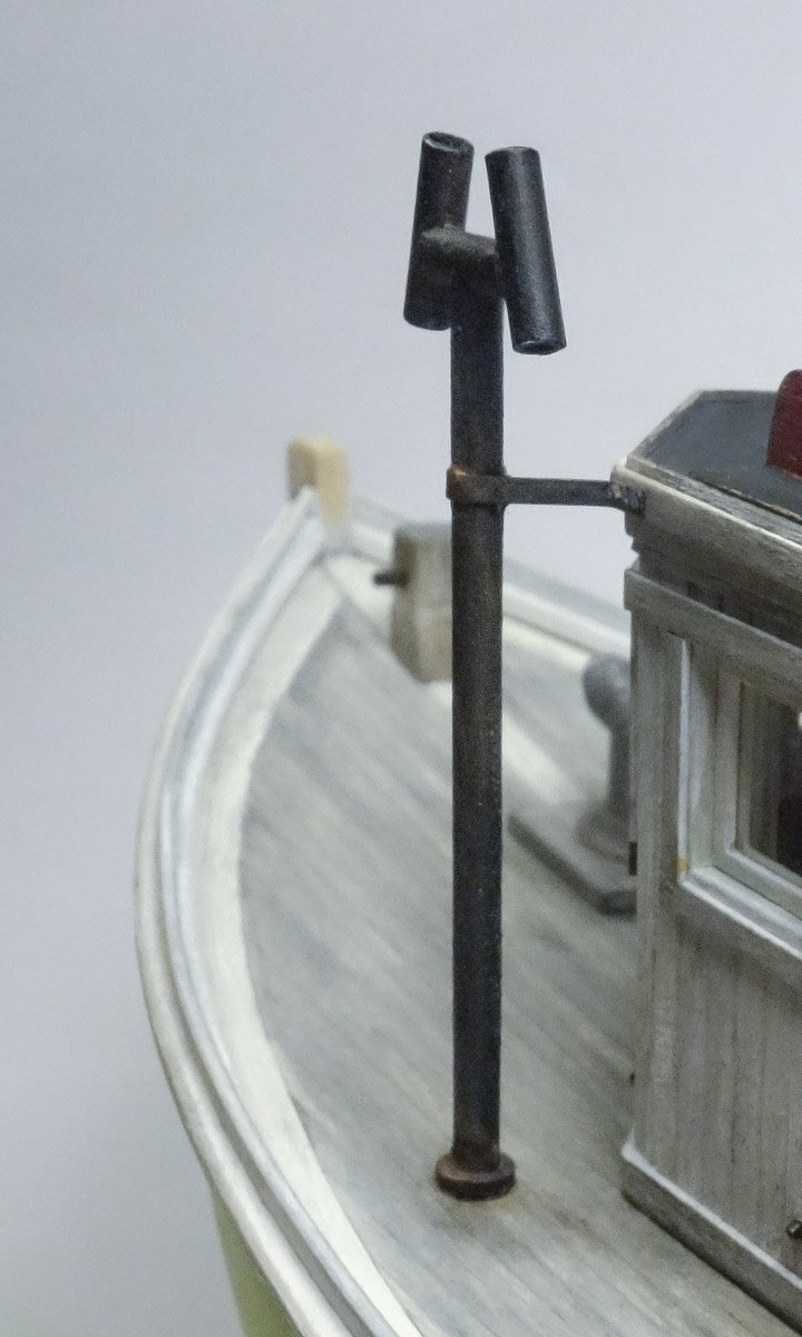
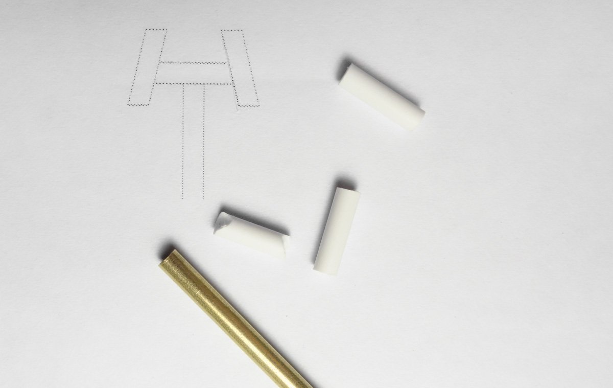
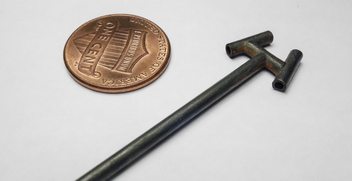
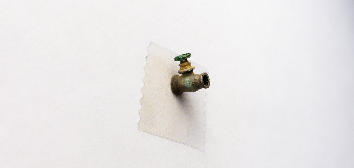
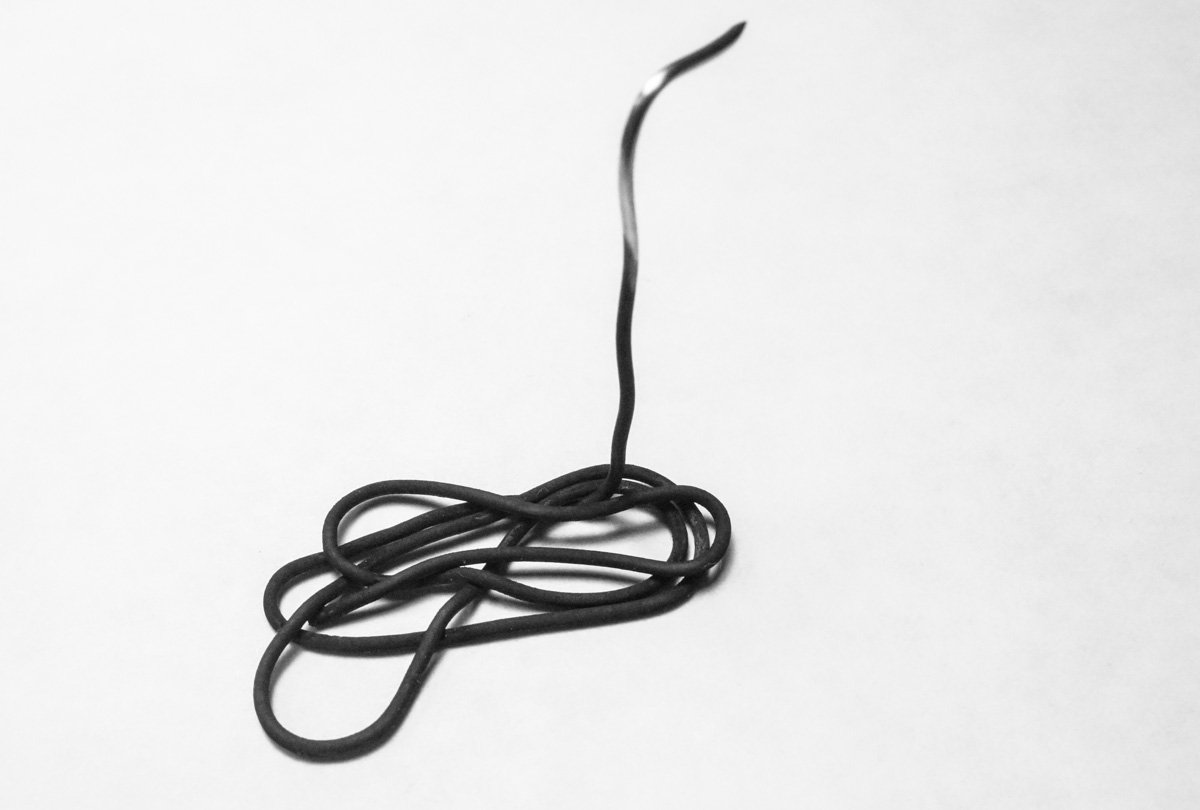
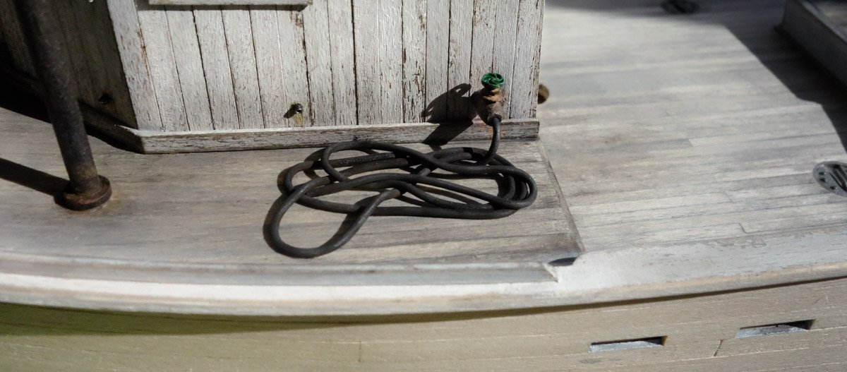
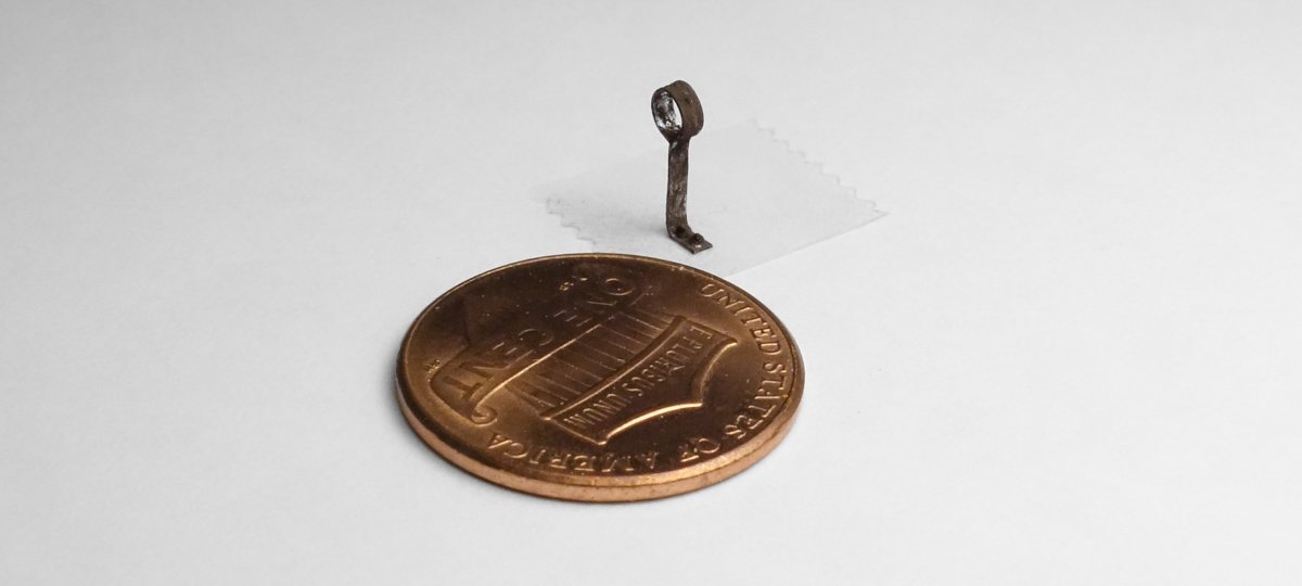
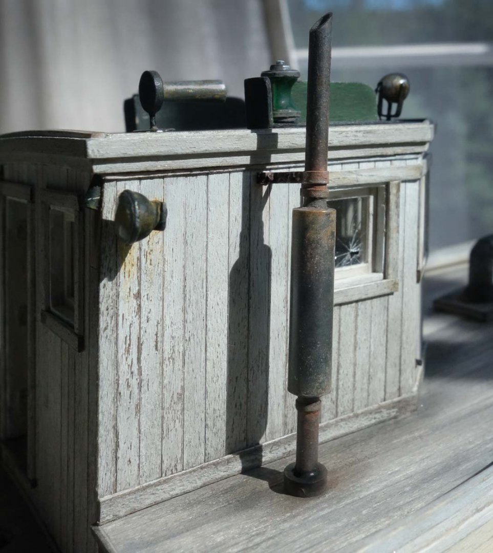
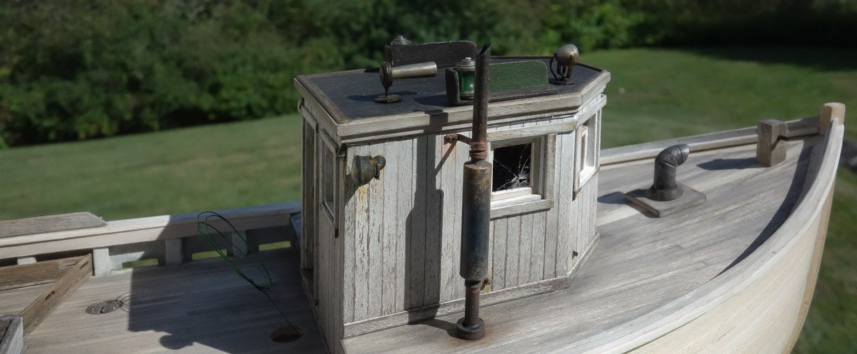
Thank you for the comment Jim and I'm glad you’re enjoying the log. Yes, those foggy, soggy salt air mornings are tough on iron and steel. Thanks for your support Druxey. I do take that as a compliment Greg, thank you so much. But it reminds me of an incident from many years ago. I was displaying an HO scale diorama at a modeling show that depicted the surface structures of a hard rock mine – headframe, ore bin, hoist, boiler, etc. The structures were weathered and there was a good deal of rusty machinery and assorted debris strewn about. A guy who had been studying the model for about 5 minutes or so came up to me and flatly stated the reason I “junked it up" was because I didn’t have the skill to do it right. I said - well, OK then. I understand this type of modeling isn’t everyone’s cup of tea, but it’s just a different style of modeling and it has been fun applying it to this fishing boat. Thanks again. Oh come on – give the guy a break. He’s just trying to make a living in a difficult climate of rising fuel costs, diminishing fish stocks and increasing regulation. But I agree, he should fix the window and change the oil. Thanks for stopping by Keith - I appreciate your support. Thanks Mark - that's the best outcome I could hope for. Thank you Alexander – I appreciate your fine compliment and support. Thanks for the complement Tom – sometimes you just get lucky. And thanks to all for stopping in and hitting the "thumbs up". Here’s a small update on the galley stove stack and deck wash down hose. First the stove stack. It is made from brass and styrene tubing that scales to about 5 inches in diameter – more or less. The pieces are cut and glued together with epoxy, then primed and finally brush painted with black enamel. The goal here was to mimic black iron pipe. So before the enamel completely dried, I rubbed it down with a paper towel that had the slightest amount of paint thinner on it. I then added a bit of rust coloration to the underside of the “T" joint. When I first looked at the close-up photo above, I noticed that the wall thickness of the styrene tubing is too thick and out of scale. I wear my OptiVisors the whole time I’m modeling and yet I didn't see this. The brutal honesty of macro photography can make you see things you really didn’t want to see - but it often shames me into going back and doing a better job. So I use a tapered round needle file and ream the ends of the tubing to a wall thickness that’s a little closer to scale. And a bracket for the stove stack made from .005" brass shim stock and a couple of styrene bolt heads. Next is the water shut-off valve for the deck wash down hose. It is meant to represent a 1” bronze globe valve, which is physically larger and can pass a greater volume of water than the typical residential style garden hose shut-off. It scales to just over 6” long and its larger size is advantageous in a couple of ways. First and most obvious is that it makes it somewhat easier to model even though its actual size is still just a tad over 1/8". Secondly, it will help in keeping it from getting visually lost as other details are placed near and around it, such as an overhanging rooftop dory, a life ring mounted above it, shrouds with wooden ratlines and so on. The valve body was fashioned from a piece of scrap white metal. The bonnet and gland flanges are stacked bits of styrene and the hand knob is an injection molded 1:160 freight car brake wheel from Tichy Train Group. It was primed and then colored with pigment powders. The hose is a piece of electronic silver solder. At .032” in diameter, it scales to about 1.5" in 1:48. It was pulled through steel wool a number of times, cleaned with alcohol and then blackened with Jax Pewter Black. The plus for using solder is that I could make it lay flat, look natural and it would stay put as I worked at forming it. The end of the “hose" was stuffed under a coil so I didn’t need to make a nozzle. The valve and hose were then glued into place. From the early planning stages of this model, I had stuck in my head the idea of using a truck tire rim mounted to the pilothouse as a hose holder. But I have never seen any such thing in any period photo of these boats where a reel or holder was used. So, no tire rim – and it really is much easier for the crew to just toss the hose into a pile out of the way. Thanks for looking in. Gary


- 424 replies
-
- 31
-
-
I just read through your build log Jim, and you should be very proud of the way she turned out. Bluejacket produces fine kits, but it still takes dedication, pride and skill to produce a model as fine as you have done. Your second build? - exceptional. Now dig #3 out of the closet. Gary
- 60 replies
-
- 1
-
-
- mary taylor
- solid hull
- (and 2 more)
-
Good to see you back at work on La Belle Poule Mark. I look forward to your updates. Gary
-
Congratulations on completing this beautiful model Alexander. I missed the beginning of this build log, so over the past couple of days I have read it in its entirety. Like your wonderful La Jacinthe - it is the work of a master modeler and a museum piece. Thank you for showing the details of how you built it. Your work is inspirational. Gary
-
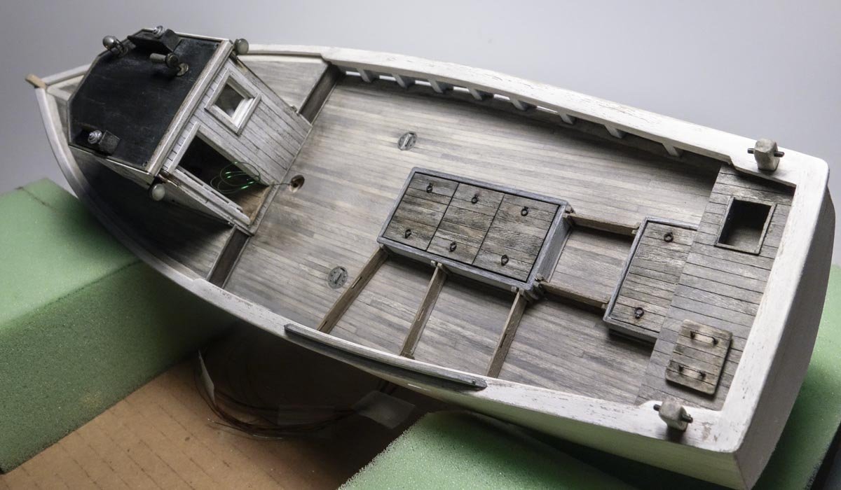
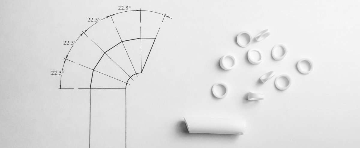
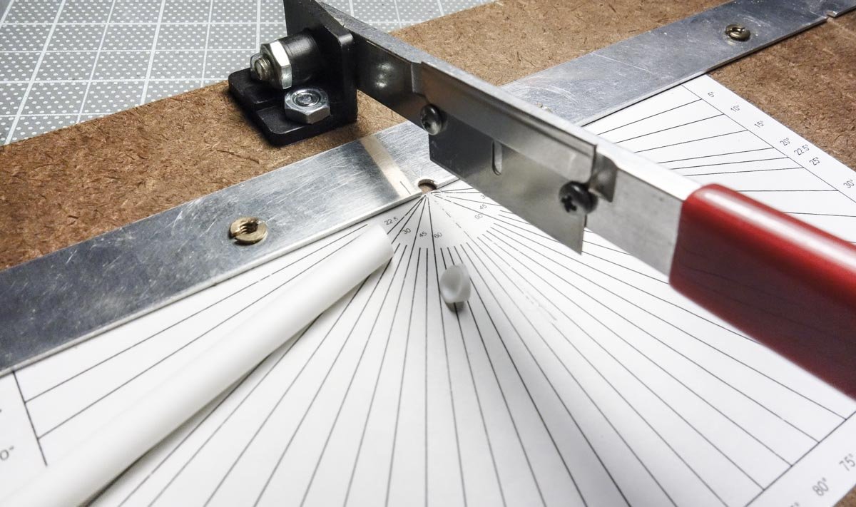
Thank you Nils, Druxey and Tom - I appreciate your fine comments and support. And thanks to all for stopping by and hitting the like button. A few forward deck details. The intake vent cowl for the galley/berth is made from 5/32” styrene tube and is put together from segments. The image below shows the geometry and the cut styrene segments. Extra segments were cut to increase the chances that I could piece together a couple that would work. I used this simple chopper in cutting the segments. I’ve owned the cutter for many years and don’t use it that often, but sometimes it’s just the ticket. I bought this one, but I don’t believe it would take an hour to build one. The pieces are glued together. Note that the first 22.5 degree segment is part of the main duct. The bow bitt is made from a piece of basswood that was cut to a scale 10" x 10”. It was colored with ink/alcohol and there’s a piece of blackened brass rod going through it. It will be glued to the deck and eventually have rope wrapped around it, so where the bitt meets the deck will not be visible. The engine exhaust stack is a scale 4.5” diameter and the muffler is 10.5” diameter. They are made from 3/32” and 7/32” brass tubing. 5/16” styrene tubing is also being used for spacers. It goes together as shown below. Two 1/8” long pieces are cut from the styrene tubing and are used to center the main stack in the muffler. Prior to assembly, the center of the muffler was heated with a mini torch to produce a bluish color. Then both the stack and muffler were blackened. I rubbed and buffed the center of the muffler to reveal the “bluing" but the effect was not as dramatic as I had hoped for - but I’m OK with it. I then put it all together with epoxy. The flanges are wrapped paper. The rusting/weathering is done with pigment powders and more will be added once the stack is placed on the boat. A bracket is made for the exhaust stack. It is made from the foil that is wrapped around a bottle of corked wine. It kind of feels like lead, but is actually two layers of foil with a plastic core. A couple of styrene HO scale nut/washers are glued on. A brass ring is used for the deck isolation collar and the stack is fitted to the model. Additional weathering is applied. And then the vent cowl and bitt are added. More work will be done to visually set the vent cowl into place - next time. Thanks for taking a look. Gary

- 424 replies
-
- 23
-
-
Very resourceful Nils - that’s going into my notebook. Wonderful engine detailing and so finely done. Very nice. Gary
-
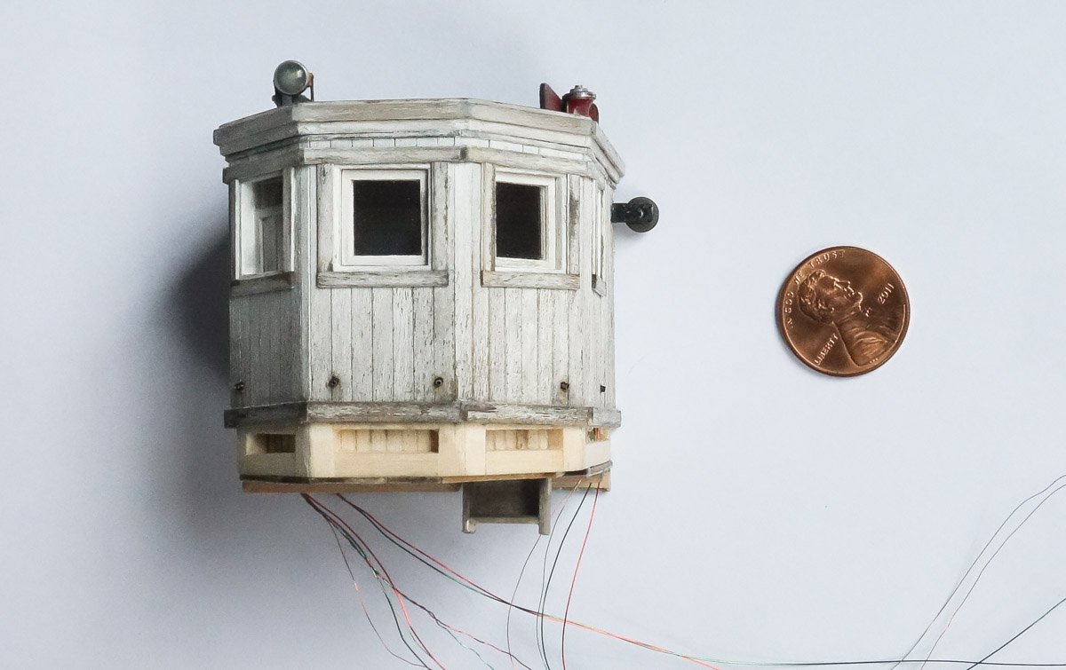
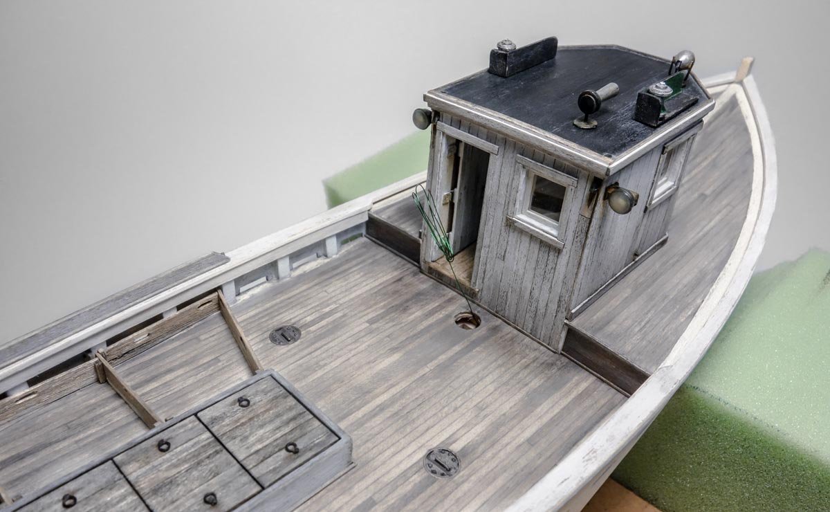
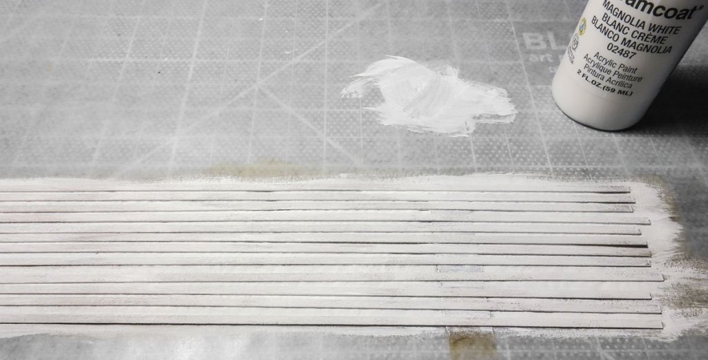
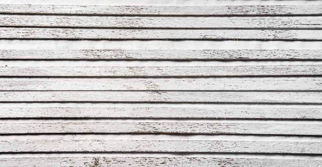
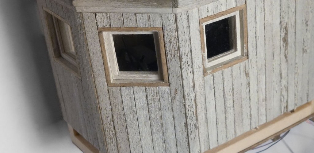
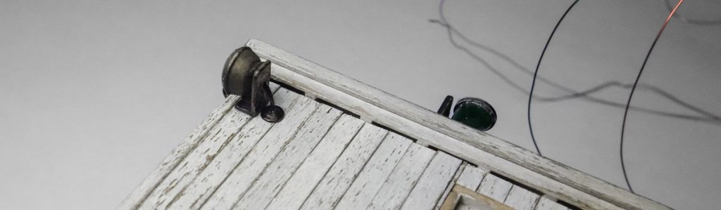
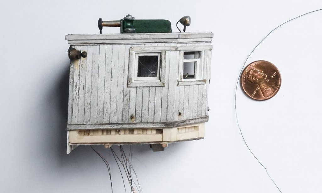
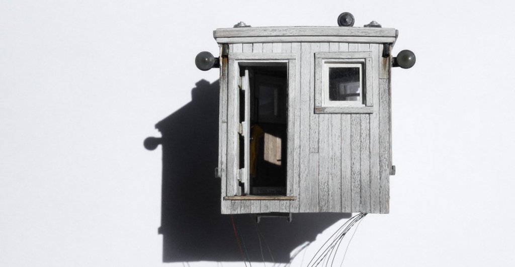
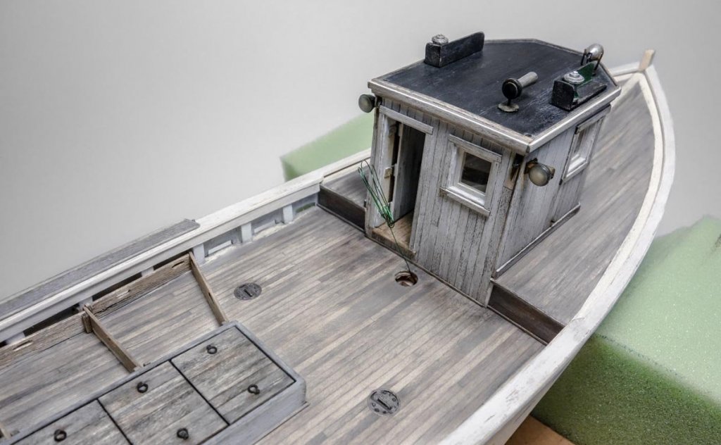
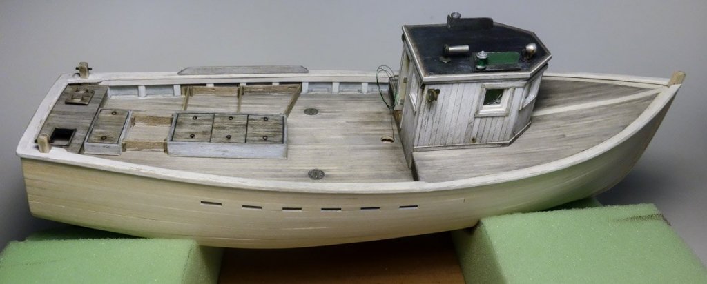
Thank you Alexander, Dan and Patrick for your kind comments and support - I really appreciate it. And thanks to all for stopping by and smashing down on the like button. Pilothouse Siding It’s time to install the roof and siding on the pilothouse and glue it to the boat. First, I thread the wires for the various lights down the interior of the walls and then glue on the roof. I glue it down in a way that I can crack it back off if I ever need to. I then determine the size and quantity of wood needed for the siding and stick it down with double sided tape to a piece of waxed paper. The wood scales to 1 x 4". The basswood is stained with regular hardware store furniture stain. Once dry, I paint the strips with an off-white craft type acrylic. After about fifteen minutes, I pull some of the paint off with cellophane tape. The siding strips are fitted and glued on as shown in the detail below. More weathering still needs to be done to reduce the uniform look of the siding, but this is a good starting point. The two aft pointing floodlights are made up next. I used a pair of 1:48 truck taillight housings that I found in my junk box and attached them to brackets I made up from styrene. I soldered up and inserted #0603 warm white LEDs into the housings and used clear Gallery Glass for lenses. The escutcheon plates are punched from .008” tin. The wires are run down the walls between the interior and exterior siding and the floodlights are glued into place. Exterior window casings, shoe base and eave trim are added. Because the windows slide down into pockets, scuppers are needed to drain the pockets in storms and rough weather. The scuppers are cut from .032" O.D. tubing. The window facing forward requires two scuppers, one in each corner of the pocket. The P/S windows have only one scupper each, which are located at the lower aft corner of the pockets. Only one is needed on these side windows because the pilothouse has a 4-degree pitch to the rear. Oddly, old photos of these boats do not show drain scuppers on every boat, which makes me wonder where the water goes when a window is left partially open and water is sheeting down into the pocket. They must have drained to the bilge or out the side somehow. The photo below shows the additional weathering applied to the siding. Weathered vertical surfaces typically display less damage at the top than at the bottom. Eaves and other protrusions provide some physical protection from the elements at the top of the wall, so paint survives there longer. But it is water that does the most damage. The bottom of the wall is the last to dry out as water runs down from above and keeps it wet longer. And the lower wall gets splash off the ground or in this case, the deck. Once water finds its way behind the paint, the wood begins to rot and the paint to peel. To simulate this wear, I brush on additional paint at the top of the wall and in the somewhat protected areas up high between the windows. I darken the lower walls with a mixture of India ink and alcohol – about one part ink to three of alcohol. I also added some short subtle diagonal markings that run from the right downward to the lower left. I did this to suggest sleet/hail damage and a possible reason for the broken window. This pilothouse is looking pretty beat especially when viewed against a clean white background. When viewed away from the background in an area where there is visual clutter surrounding it, it doesn't look quite so bad. So as I work on weathering, I keep checking it against a clean background to get a better sense of the level of damage I’m inflicting on it. It is easy to get carried away and it’s difficult to turn back. Finally it is glued on to the boat. Some weathering of the deck will be required to make the pilothouse look like it belongs there - but that’s another time. And before the pilothouse is complete, I still need to add life rings, a roof top dory, a water spigot and hose for washing down the deck and maybe a grab rail or two. Thanks for stopping by. Gary


- 424 replies
-
- 28
-
-
What a beautiful model Alexander. The color of the sails blend so naturally with the tone of the pear and contrast of the black hornbeam. Very nice indeed! A true museum quality masterpiece. Your build has been very inspiring to me. You have shown how much can be achieved with little in the way of equipment - just ingenuity, skill, artistry and determination. Thank you for sharing this with us and the steps of its construction. Gary
- 306 replies
-
- 5
-
-
- schooner
- la jacinthe
- (and 1 more)