

bruce d
-
Posts
3,046 -
Joined
-
Last visited
Content Type
Profiles
Forums
Gallery
Events
Everything posted by bruce d
-
I can jump in here with the results of a LOT of digging a few years ago: Pickle never had her lines taken off. All models are 'best guesses' and Adonis is my 'best guess' as to the source of the Caldercraft kit. The good news is that there is a very well researched book that untangles the confusion arising from there being two craft of the same name on the books at the same time and gives a good account of Pickle and her captain, Lt. Lapenotiere. I tried and failed to find fault with his research and conclusions (me failing to find fault is uncommon... sigh.) HMS Pickle: The Swiftest Ship in Nelson's Trafalgar Fleet by Peter Hore, published by The History Press.
-
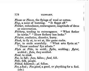
 Me again. It is interesting that the term seems to refer to a specific pattern in some examples. In coachbuilding (see my comment in post #2) it covered the practice of painting a panel or area with a pattern/motif. The text below is closer to this usage. HTH
-
EMCO commissioned Gerald to write a book on using the Unimat. He was a good advocate for the lathe and accessories and was brutally honest when discussing them. I heard that Elliott either merged or was taken over but don't know the story.
-
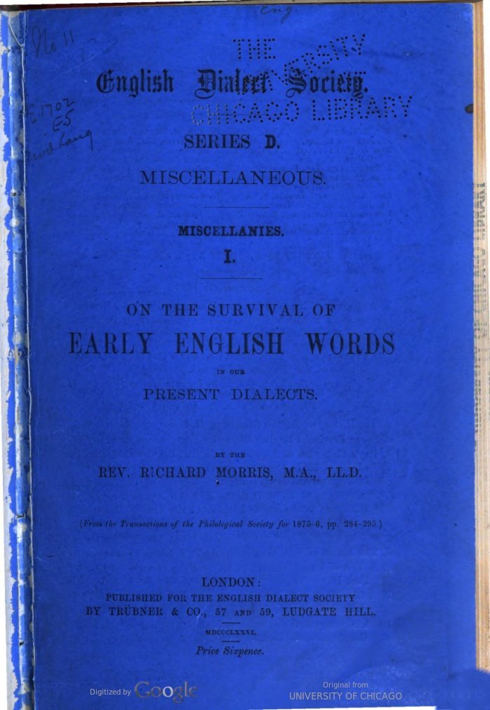
Next to last paragraph. This definition is new to me. flother.pdf
-
Unimat was the Austrian maker, 'EMCO' (Elliot Machine Company) was the UK distributor. They had their own badges but there was no difference in the product. The names are now intermingled in use. I love 'em, prefer the SL/DB over the Unimat 3 but that is just my point of view.
-
I can help with 'flothered': it means the painted ornate fiddly bits. The term was still in use by coachbuilders up to 1900ish.
-
Thanks Craig, you nailed it. No surprise, just sad.
-
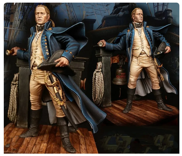
This figure is for sale through a few traders on Alibaba. It is 1/24, resin and has no manufacturer's name: does anyone recognise it as a copy? If so, who is the legitimate source please? Thanks, Bruce
-
Hello Robert and welcome to MSW from Sussex.
-
If I recall correctly, a caption in a contemporary magazine described the car as 'Corvette silver'.
-
Now that really takes me back. The kit was a great source for parts and served as an organ donor for a couple of my altereds and rails. Good kit, mind if I watch?
-
Welcome to MSW from the UK.
-
Welcome to MSW from the UK.
-
Hello Jölle and a warm welcome from the UK.
-
I'm wondering if the mystery items are for a specific task. I have read of a carpenter preparing a ship's boats used for anchor work or artillery transport and assumed it was fitting the needed items rather than making any permanent modifications. Having fruitlessly spent some time trying to find details of any of these modifications I concluded the shipwrights and carpenters were directed in some way that was not recorded. The one area where I know very specific arrangements were made was in preparing boats for launching Congreve rockets but alas, they do not appear to have survived. FWIW, I will dig out a drawing I found showing the proposed method of outfitting a boat of that period with a slide for mounting an artillery piece. If memory serves it used rollers ... who knows if it fits but we'll see? HTH, Bruce
-
Rolltop Desk by kgstakes - 1/4 scale
bruce d replied to kgstakes's topic in Completed non-ship models
Very cool, Kurt. I can instantly think of a dozen questions about this desk so, yes please, I would like to see a log and get a look at your processes. Bruce- 1 reply
-
- 4
-

-
Kinsale played a big role in the 17th and 18th centuries and built at least one RN frigate, HMS Kinsale. Kinsale Dockyard - Wikipedia According to this page HMS Kinsale was the only ship built there for the RN: List of frigate classes of the Royal Navy - Wikipedia Nothing I have found in The National Archives catalogue contradicts this. There was a lot of activity but it was almost exclusively maintenance and repairs. Ireland produced a lot of shipwrights for HM shipyards but I speculate that this was due to a healthy trade in merchant craft. HTH, Bruce
-
Thanks Druxey, you bet. I am not made of the right stuff to attempt doing it in one piece.
-
It looks like Apollo has landed on his feet. He's a cutie!
- 443 replies
-
- 4
-
-
- Indefatigable
- Vanguard Models
- (and 1 more)
-
Pretty impressive, Chris. You are slowly eroding my resistance to card models ... oh dear, another rabbit hole .
-
Update: I'm chipping away at the frames as time allows, will post photos when I reach a natural break. Also, work has begun on the fixture to hold work in progress for stern decorations. The Society of Model Shipwrights is linked with MSW as a chapter club. A talk on building Berwick is now on their channel: Bruce
-
18-Pounder Pivot Gun
bruce d replied to AndyHall's topic in CAD and 3D Modelling/Drafting Plans with Software
These may be of use: Rijksmuseum Rijksmuseum HTH, Bruce -
FM, good advice (as usual) from Allan, and another book by Philip Reed is close to your stated needs: PERIOD SHIP MODELMAKING An Illustrated Masterclass It's on Ebay, AbeBooks and other places as well. In iit he walks us through building Prince de Neufchatel in 1/192 scale. McNarry and his wife were superb modelmakers and won quite a few pots at early Model Engineer Exhibitions in London. HTH, Bruce
-
Size of a printer needed
bruce d replied to Frank Burroughs's topic in Modeling tools and Workshop Equipment
What Allan said, plus check the lines with a straightedge and measure the diagonals (corner to corner) for skew. -
Hello Paul and welcome to MSW from the UK.

