tlevine
-
Posts
1,938 -
Joined
-
Last visited
Content Type
Profiles
Forums
Gallery
Events
Everything posted by tlevine
-
 This sheer plan is for Atalanta but they were of the same class, with very little difference between them. https://commons.wikimedia.org/wiki/File:Atalanta_(1775)_RMG_J4428.png Even with volumes I and II of TFFM, without a set of plans, you will not be successful in building Pegasus.
 -
Echo by tlevine - FINISHED - Cross-Section
tlevine replied to tlevine's topic in - Build logs for subjects built 1751 - 1800
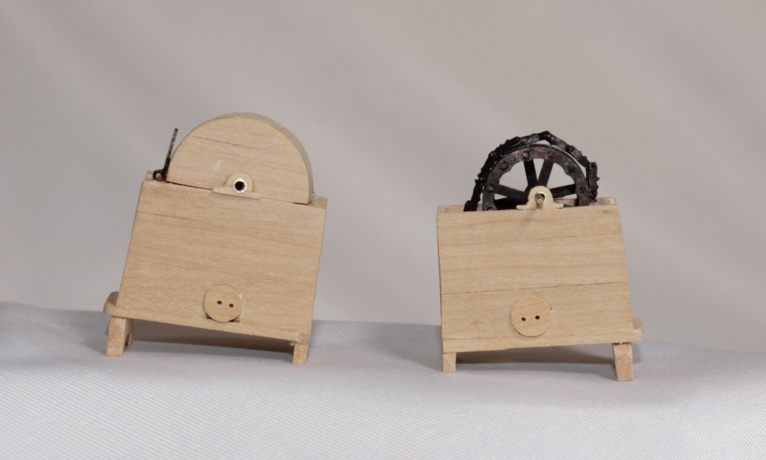
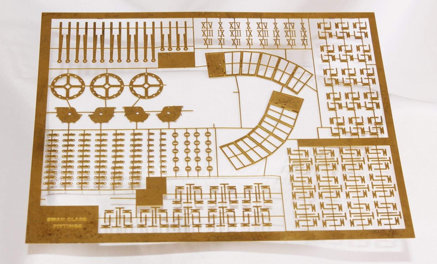
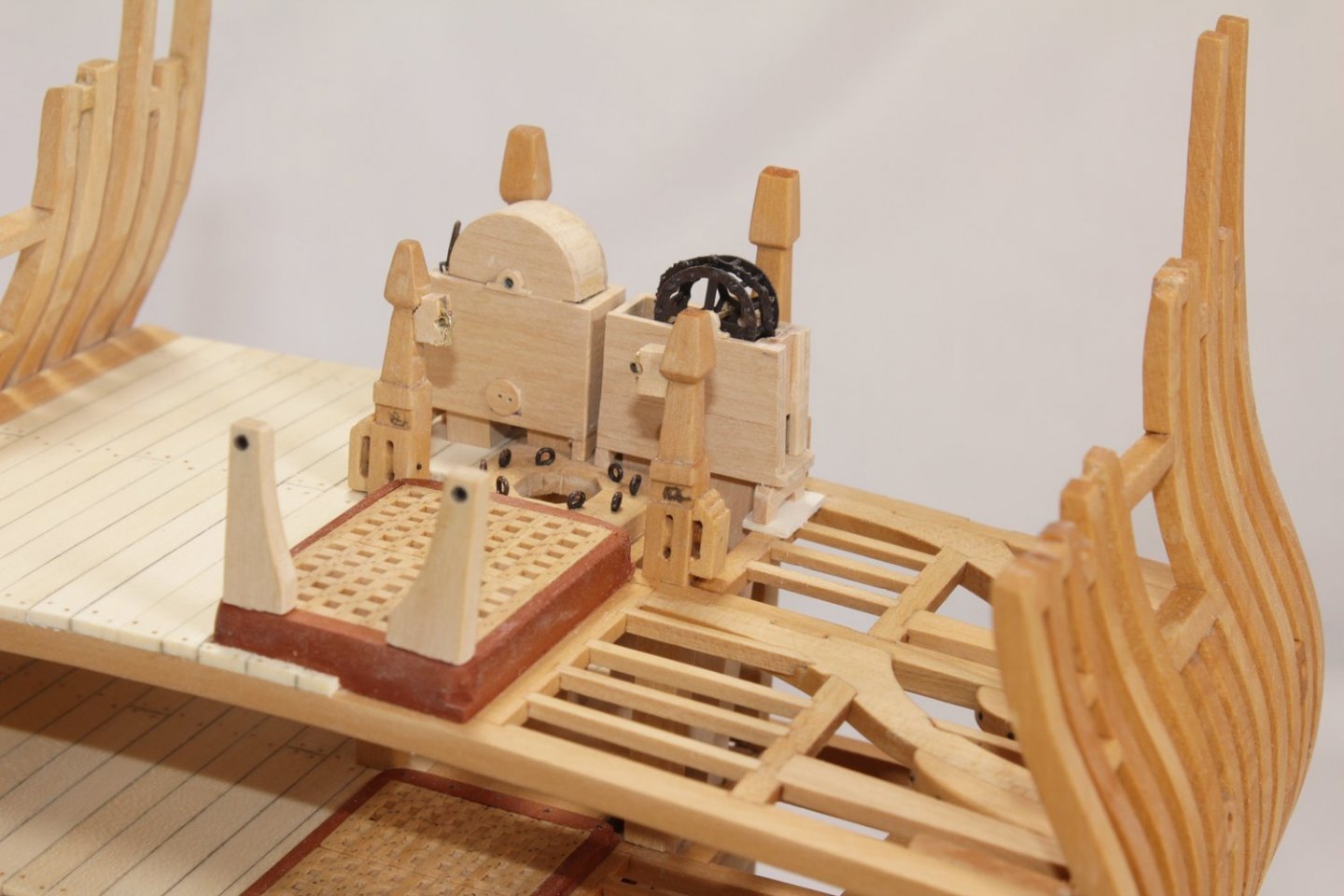
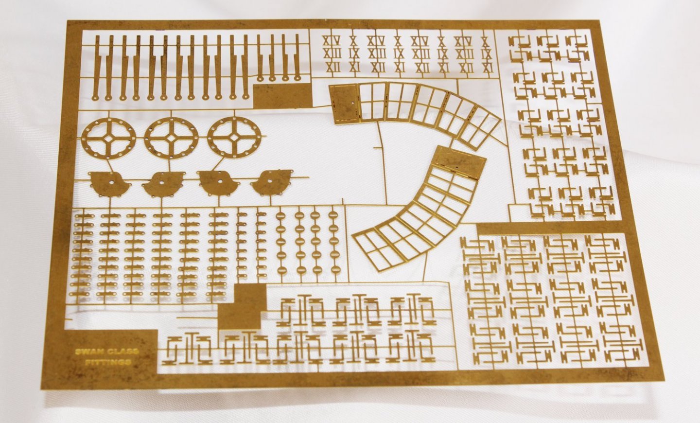
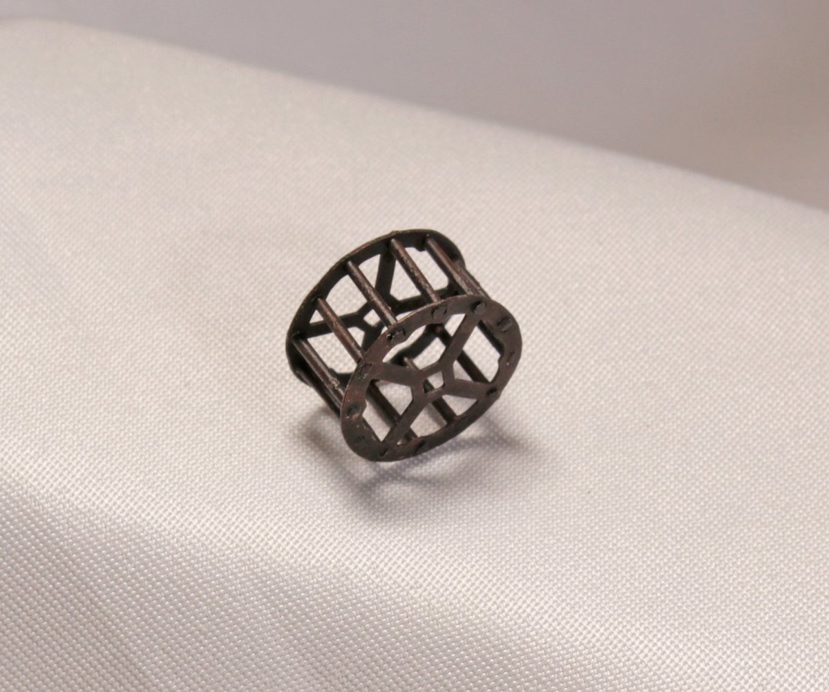
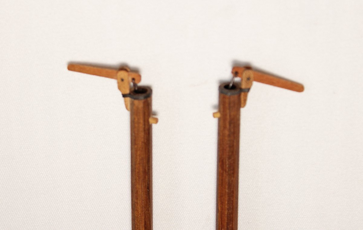
The next items to be make are the cisterns and winches. I decided to show the starboard cistern with its hood and the port cistern open, showing the sprocket wheel and chain. The cisterns are straight forward in their construction. They are simply a box with openings in the bottom for the pumps, and a slide on the outboard side to allow insertion of the pump dale. The inboard legs rest on the mast step and the outboard ones are on the deck. I was lucky enough to have a sheet of photo etch from Admiralty Models developed for the Swan class. They are no longer available. I used this for the sprocket wheel. The photoetch sheet has the rim of the wheel; short lengths of brass wire were silver soldered to them. I also made a segment of chain from pieces of the same photoetch sheet. The next photo shows my tipsy cisterns. The drainage plugs are in place. A rope handle in the plug will be added later. The chain was lifted up to illustrate the detail in the photoetch. The winch assembly is supported by rhodings on the cistern hood, bitt pins and end support pillars. The hood and pillar rhodings are repesented by brass tubing. Those on the bitt pins are inset into a spacer block, as seen in the last photo. These will all be blackened.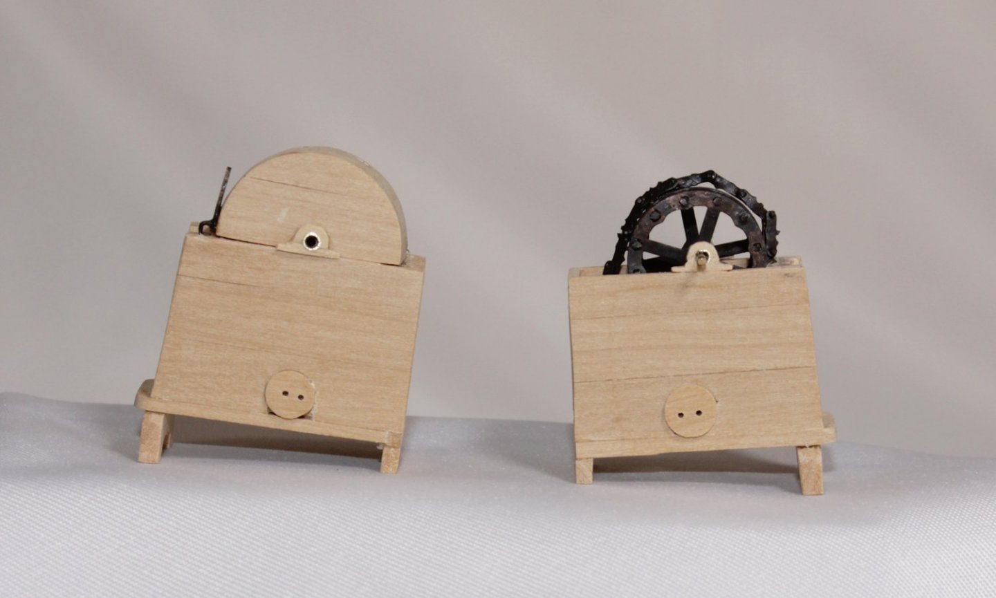
- 52 replies
-
- 19
-

-

-
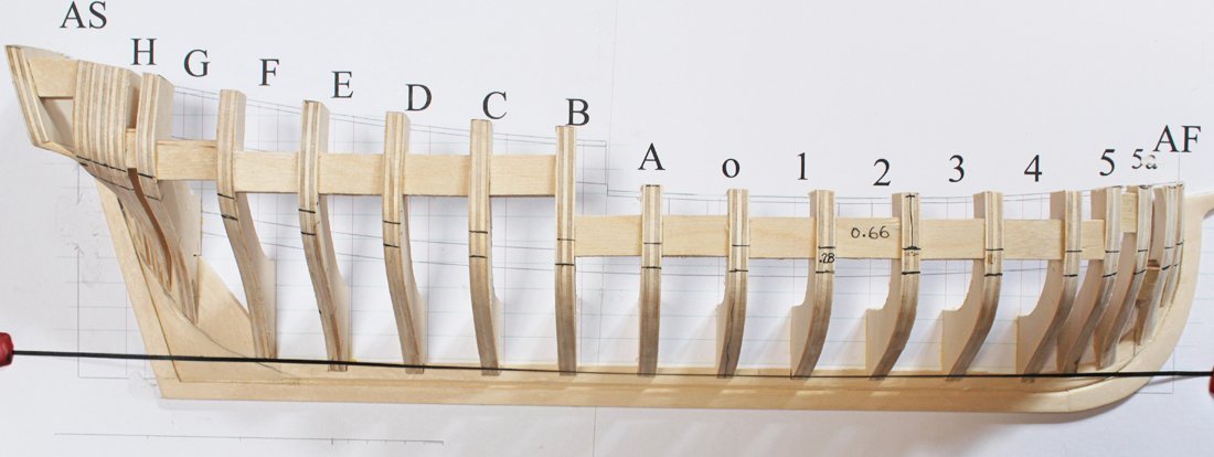
This is the picture from the manual. As you can see, either the top or the bottom of the wale is accessible with a machinist's square...or at least my machinist's square. As stated in the instructions, "...mark the top and/or bottom of the wale. This is indicated by curved blue lines on the plan. Unlike the planking on the lower hull, the width of the wale is the constant throughout its length..." Comparing your photo with this one, the only difference I see is that the spacers mid-hull are higher on mine. Looking at your half-hull, I would suggest running either a plank or tape along bulkheads aft of F. In the picture you posted, it looks like more fairing will be required.
-
Looks great, Eric. The concept behind the project was to help remove the fear of scratch building. What's next?
-
NAIAD 1797 by Bitao - 1:60
tlevine replied to Bitao's topic in - Build logs for subjects built 1751 - 1800
Most importantly, your work is incredible. I wish I had half your talent. I agree with you that the color of the wales is too brown. How are you planning on fixing it? -
Mary, welcome to MSW. Great to see another woman modeler. Please introduce yourself to us here: https://modelshipworld.com/forum/3-new-member-introductions/
-
For removing soft solder, I would recommend files or wet/dry sandpaper to prevent damage to the rest of the part.
-
Echo by tlevine - FINISHED - Cross-Section
tlevine replied to tlevine's topic in - Build logs for subjects built 1751 - 1800
I should have mentioned this earlier. For anybody considering this model, I have one word of advise. Do not measure off the practicum. Unlike the drawings in TFFM, these drawings are off scale by up to +/- 6%. I initially thought it was my printer but after three printers gave me the same error... If you need to make a template, import the plan into a CAD or drawing program and, using the measurements cited in the text scale the image as needed to get the correct scale. -
Echo by tlevine - FINISHED - Cross-Section
tlevine replied to tlevine's topic in - Build logs for subjects built 1751 - 1800
Thanks for all the likes. Greg, I also had problems with the locations of the pumps extending into the well. I adjusted the brake pumps location to compensate. I had to do the same thing with the outer chain pumps. The port pump extends all the way down to the channel. I truncated the starboard one for the simple reason that I ran out of wood and did not want to make up another one. The chain pump boxes extend all the way down. -
Echo by tlevine - FINISHED - Cross-Section
tlevine replied to tlevine's topic in - Build logs for subjects built 1751 - 1800
I have had a little more time to work on Echo. The upper deck planking has been laid. Parts of it were laid twice since I forgot to locate the openings for the pump tubes. And speaking of making things twice, my new motto is measure three times, cut once. I discovered that somehow the location of the chain pump openings in the mast step was off by 1/8". I am happier with the remade step anyway. The ringbolts have been installed surrounding the mast opening. The next step was to begin installation of the pumps. There are a pair of brake pumps and a pair of chain pumps. Temporary chain pump cases have been installed. You can see from the picture that they are vertical but form a V-shape when viewed fore-to-aft. The brake pumps are octagonal. I made these in the V-jig that is normally used to shape masts. A chisel was used to knock down the corners of a square blank the final shape was obtained with a sanding stick. The pump was bored by chucking it on the lathe and putting a drill bit in the tail stock. A second hole was drilled for the discharge spout. I wanted a color contrast; they were made from apple. I apologize for the out of focus picture. The pumps are temporarily installed. Next up is the cover and winch for the chain pump.

- 52 replies
-
- 17
-
-
For anyone who purchased this project, the revised plan set it available from the office. Just drop Mary a note at info@thenauticalresearchguild.org.
-
https://www.riogrande.com/product/stoddard-crimped-wire-brass-brush-mounted/338407
-
That is a good suggestion, Capella. I have been doing this for more years than I want to admit and I am still learning new words! BTW, welcome to MSW.
-
First, new drawings have been made of the coamings, gratings and capstan step. The original drawings will work; it simply will not look like the prototype. I will be submitting them to the office so that they can be distributed to anyone who has purchased the project. If you need them sooner, send me a pm. Second, my directions describe how I made them. You are right; pieces of wood 7" x 3 7/8" and 5 5/8" x 4 1/4" would work. Feel free to use different sized wood to get the same result. The extra 1/4" gives me a little "breathing room" to sand the wedges to the final dimensions. It is much easier to take off wood than to put it back. The whole idea is to have alternating wedges so that the whelps fit securely onto a flat surface and are evenly spaced. The recesses made with the alternating wedges is only 1/16".
-
Yes, I do it in sections, drilling from the exterior side of the frame.
-
I absolutely love my carbide bits but I would never consider putting them in a pin vise. Any lateral pressure and they will break. That is just the nature of the metal; it has nothing to do with price. I buy resharpened ones from Drill Bit City. As far as rotary tools are concerned, I just use a small cordless Dremel. It is variable speed. The collet holds the bit steady enough to prevent breakage. For a task like drilling the holes in frames, I put the bit in the sensitive press on my Sherline mill.
-
I have figured out what I did wrong; have no idea why I messed up. There should only be seven rows of grating battens, not eight. Adjusting the length of the head ledges to 42" solves the problem. I hope to have the corrected drawings finished this weekend.
-
If you think you have a headache, I am going crazy trying to figure out what I did wrong and where, as well as make up new drawings. It looks great, regardless.
-
I never noticed the discrepancy until you just pointed it out to me. I would correct my mistake by moving the carlings out so that half of them are exposed. Nobody will see the original mortice. Again, my apologies.
-
I think you could get away with trimming the base. However, the brakes will be too long as drawn so you will need to shorten them. Having said that, the base is one of the easiest parts to build. I would make another one. Soak your base in isopropanol and you will only need to remake the upper center piece. I would "fudge" on the lower and simply shift it over so the holes align.
-
Echo by tlevine - FINISHED - Cross-Section
tlevine replied to tlevine's topic in - Build logs for subjects built 1751 - 1800
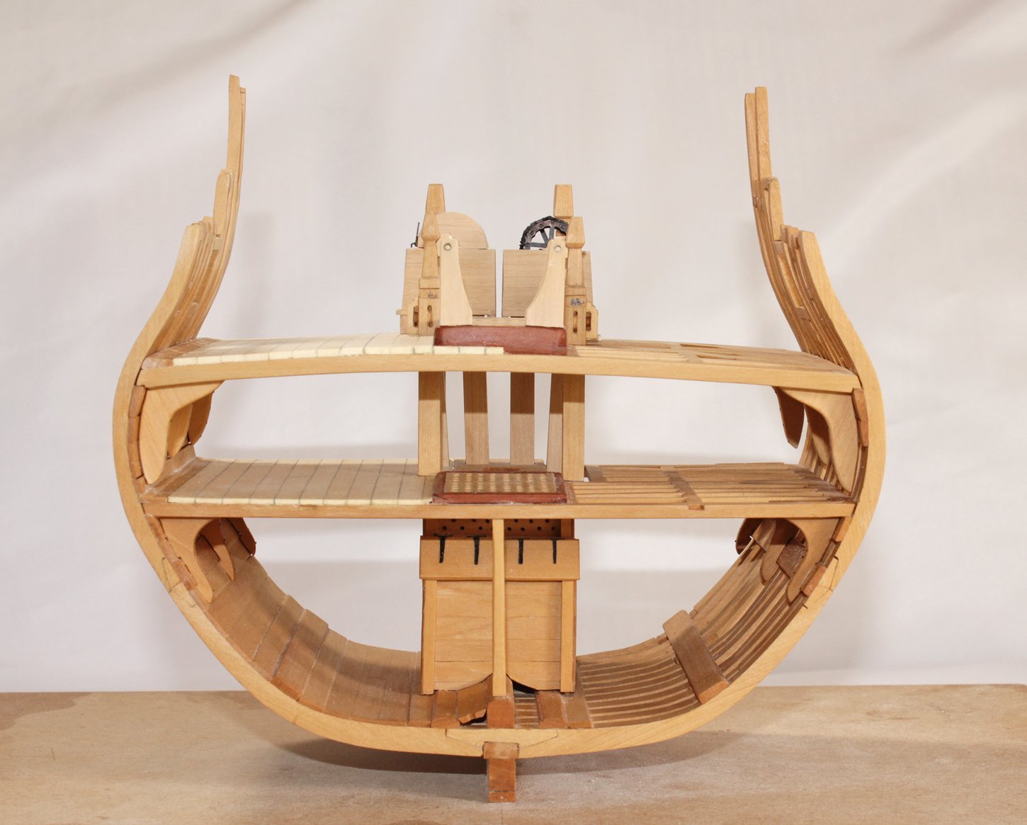
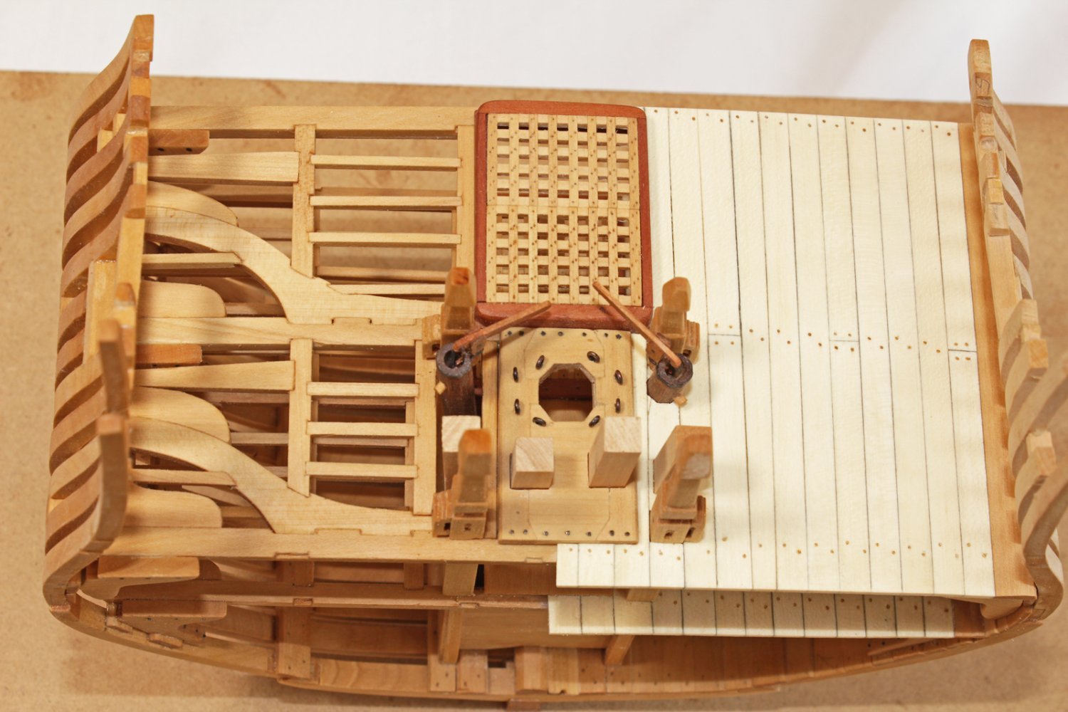
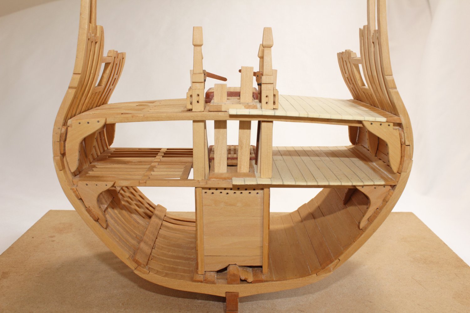
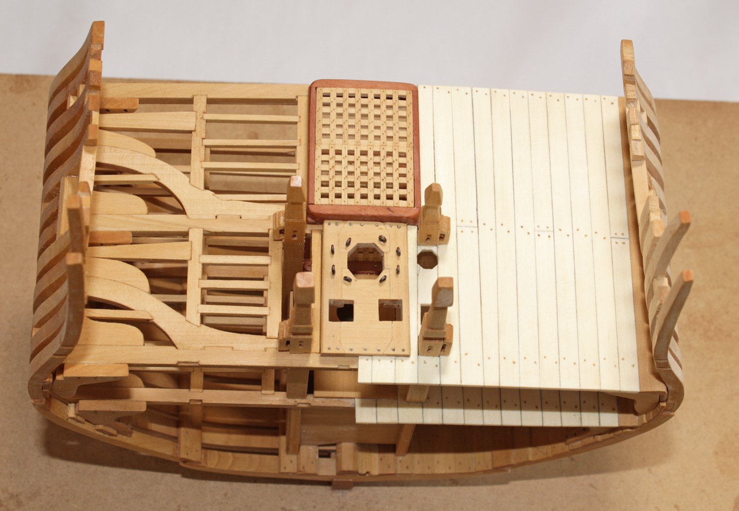
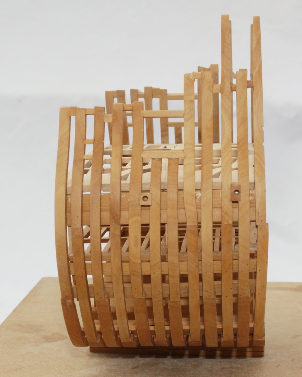
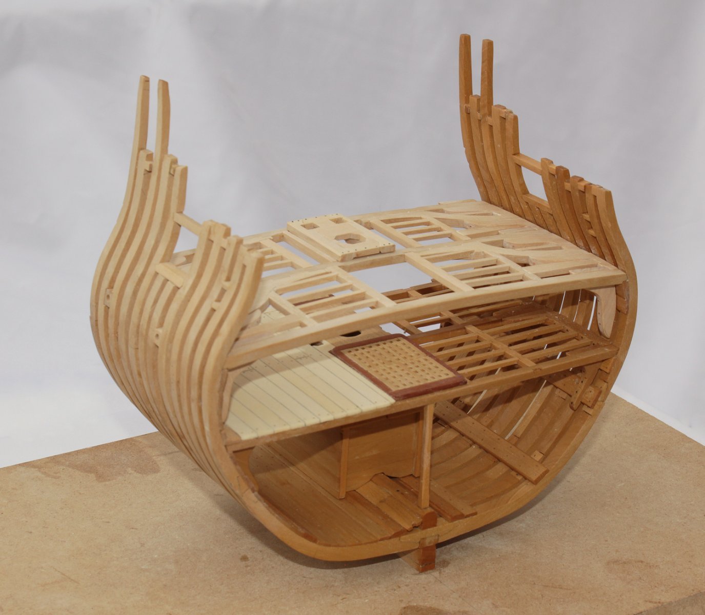
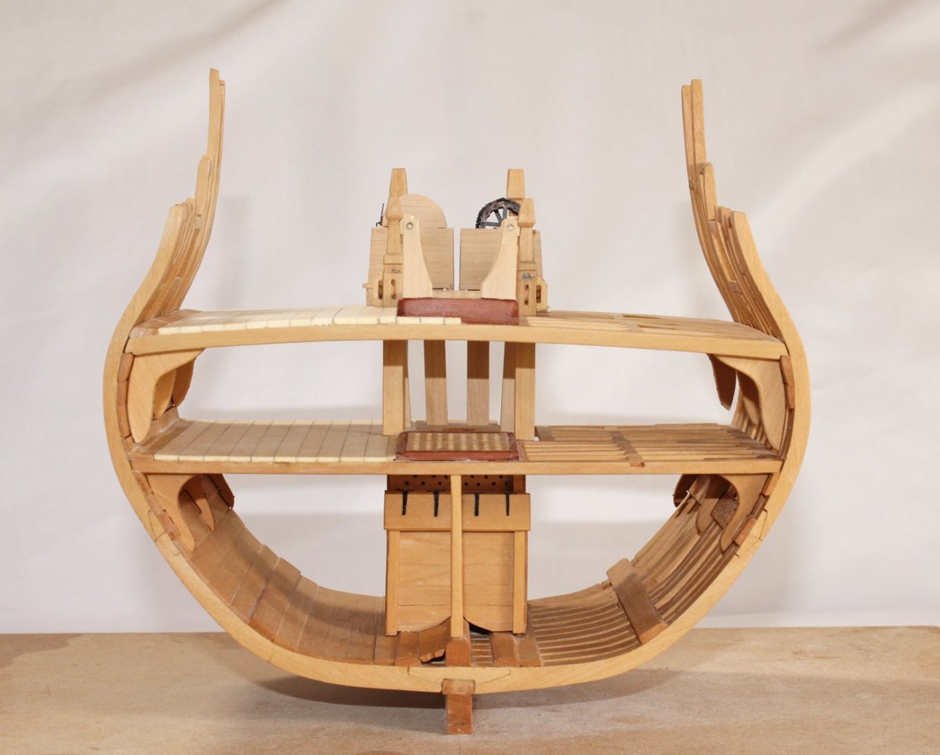
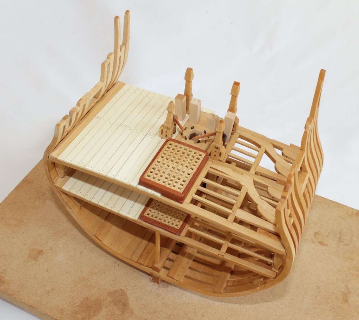
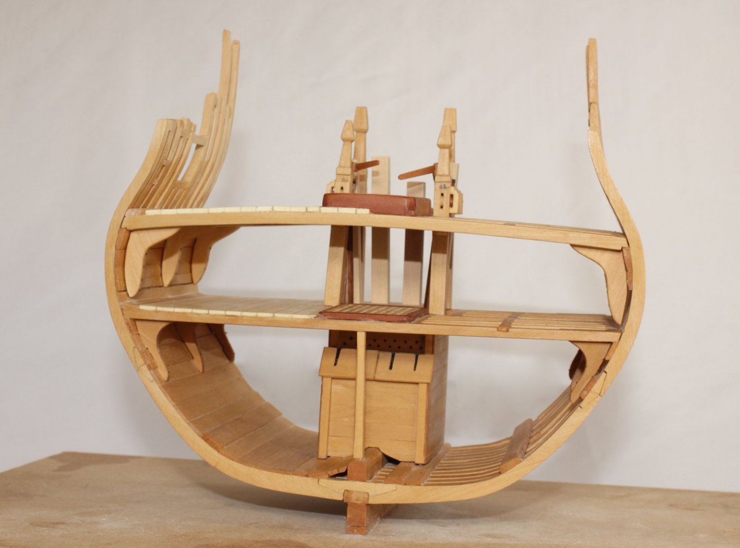
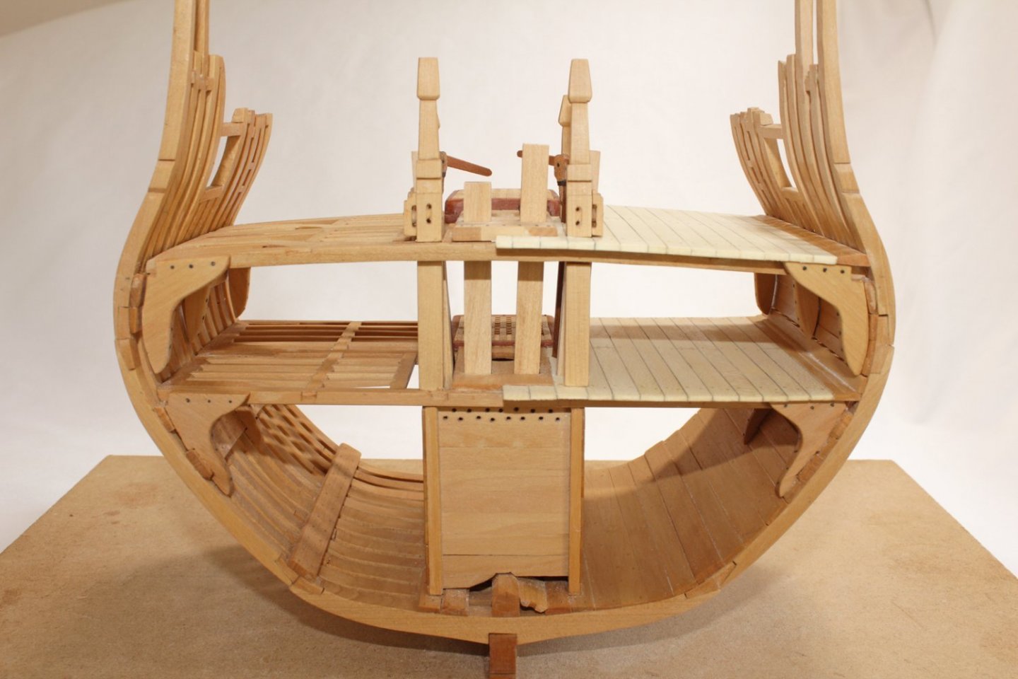
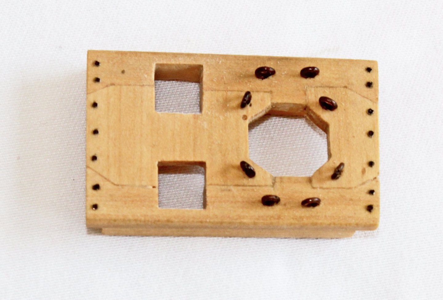
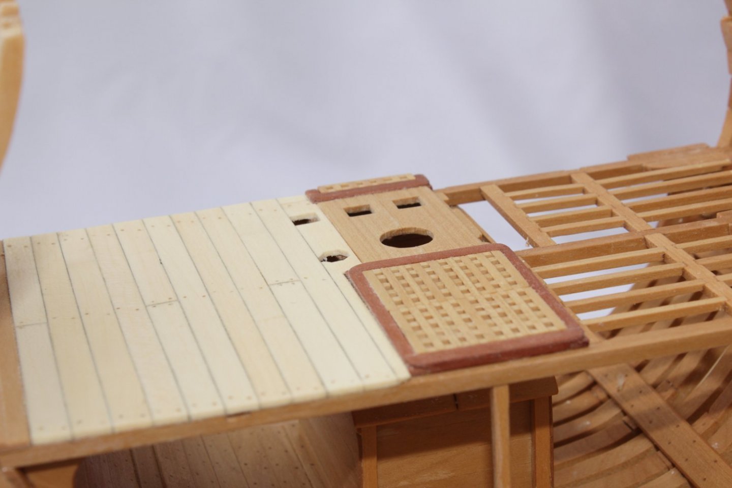
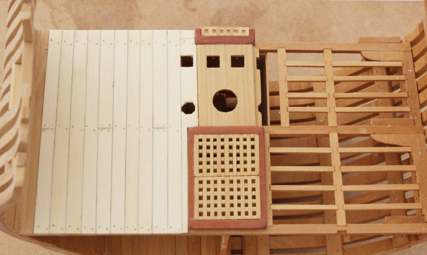
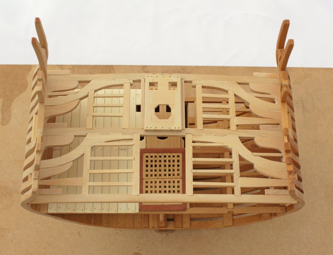
It's only been 3 1/2 years since my last posting! Swallow is on the shelf until Spring. I have decided to return to Echo, hopefully taking it almost to completion in the next few months. I have now finished the lower deck. The port side will remain in frame and the starboard will be planked. The gratings are made in two pieces using the same technique I showed in the capstan construction. The key is to have the grating made first and then fit the hatch coaming to the grating. Everything is made from castelo unless otherwise stated. The coamings are made from cherry. The lower mast partners are in place. The square and octagonal holes are for the pump tubes. The deck is planked with holly and the treenails are bamboo. In this cross section, the hatch abaft the mast partner is just visible, along with a bit of grating. The upper deck framing has been completed. The mast partner are much more complicated on the upper deck. Compare the pictures above and below. The two missing starboard ledges have been installed since the picture was taken. The beauty of a cross-section is that I can slide out the entire deck to work on it away from the model. Finish has been applied to the completed lower deck and the port hull exterior. The Watco's really gives the castelo a warm look without any shine. Next up are the upper deck hatches.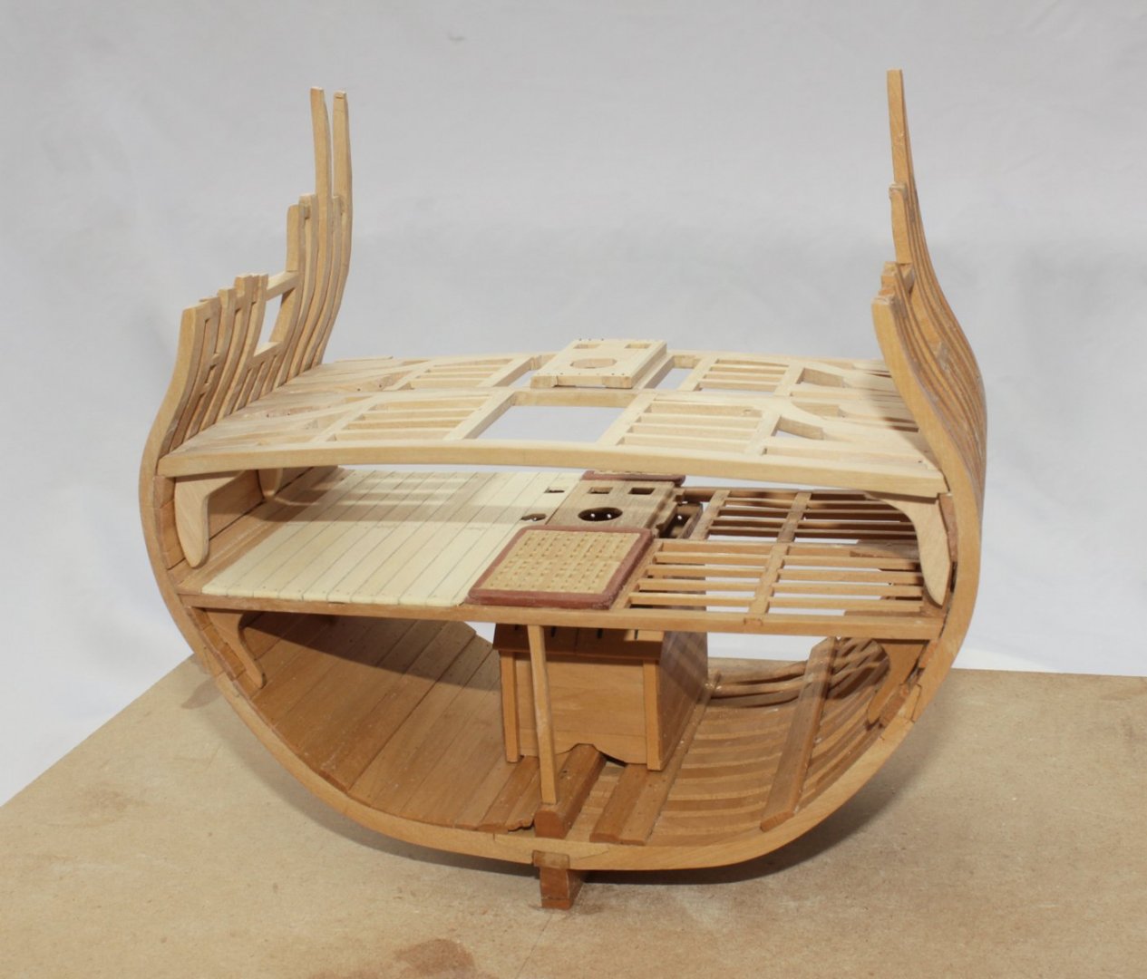


- 52 replies
-
- 20
-
-

-
I am in total agreement with Greg (although my patients only had two legs). Phenomenal work.
-
Here are some new options. https://thenrgstore.org/collections/model-figurines
-
Looks like your schedule is pretty full, Grant. The capstan looks fantastic. Thanks for sharing with us.