


Heronguy
-
Posts
863 -
Joined
-
Last visited
Content Type
Profiles
Forums
Gallery
Events
Posts posted by Heronguy
-
-
Thanks for your comments Ken. So far I find handing the unit off frame is quite easy but I can try the stiffener via diluted glue just to see how it works. Although I haven’t mounted the shrouds and reeved the deadeyes I have tried tugging on individual shrouds to see if the knots slip and ruin the ratlines. They have held fast so I am confident this will work out!
A question - is there a diffence in appearance or performance of “white glue” vs carpenters glue - the brownish stuff. I’ve haven’t tried white glue since it messed up the hull of my Prince de Neufchâtel!
- Canute and John Allen
-
 2
2
-
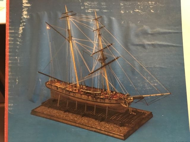
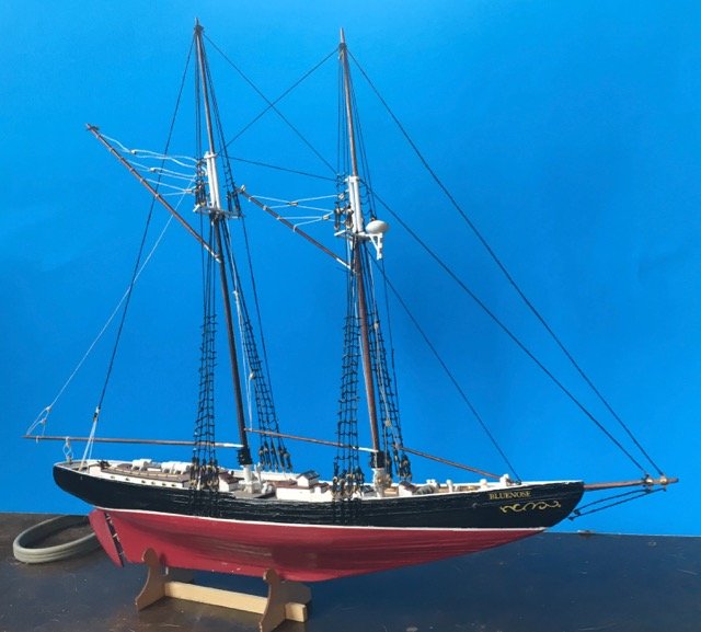
At the same scale as the Syren we can see how much ship she is!
-
33 minutes ago, michael mott said:
Knot having made ratlines for a model looking at the jig leads me to my first question which relates to the sequence of placing the shrouds on the mast. I am given to understand that these are placed over the mast working alternately from port to starboard (maybe the other way round) which this jig doesn't seem to account for, unless I am not understanding something.
Michael
You may be correct although having handled my 1st trial set I can imagine alternating them by making both port and starboard set and then looping them in turn over the mast. I'll try that on my Bluenose II shrouds and report my experience. I'll also look forward to Ken's comments on the matter.
- John Allen and Canute
-
2
-
Dave,
I haven't got that far yet so I can't address your issues. Ken, the creator of the jig, has indicated his success with the approach so the problems may not be so bad. The question of alternating port pair - starboard pair over the mast is an interesting one. Similar to the issue I have with the singleton (odd) shrouds. Historical accuracy may be a gotcha for this approach! For those of use who aren't (yet?) concerned about historical accuracy then this may be a good solution. I'll still reserve judgement at lsat until 3rd impressions.
-
First impression - part 2 (or is it Second impression??)
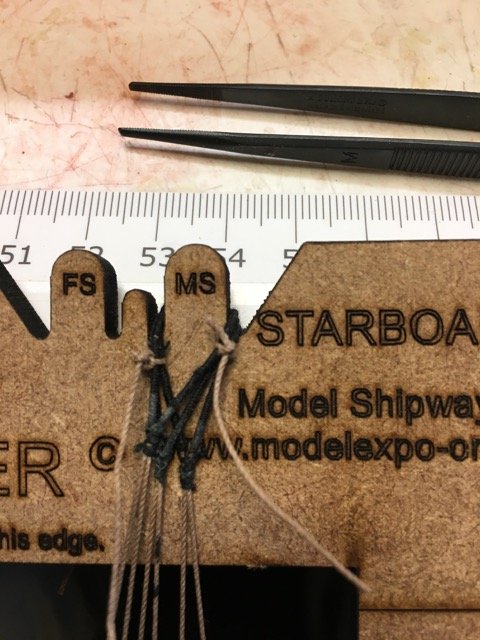
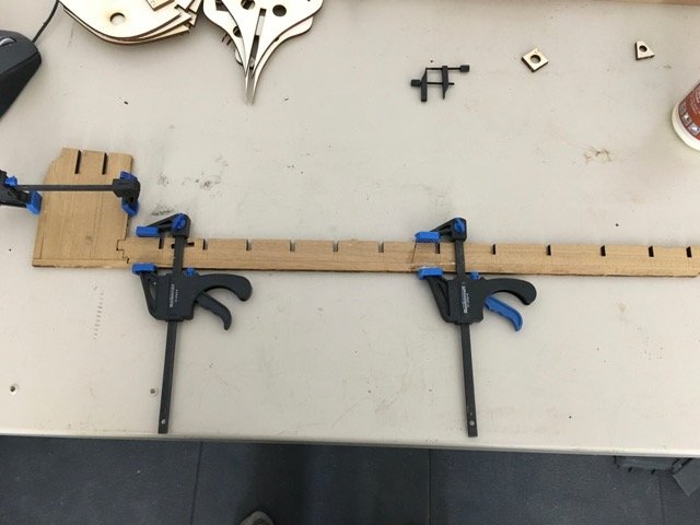
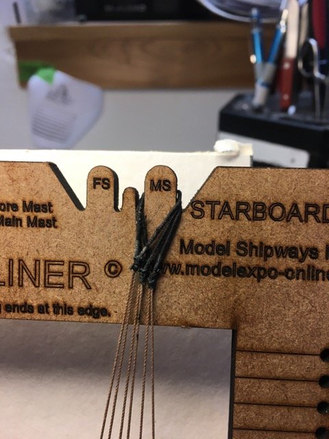
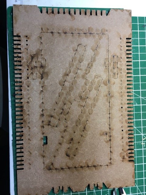
I' have cut my trial shrouds off the Ratliner. It is easy to do and the resulting unit is robust and easy to handle.
Once the ratlines were all snipped then I tied off the loops at the topic order to keep them together and organized.
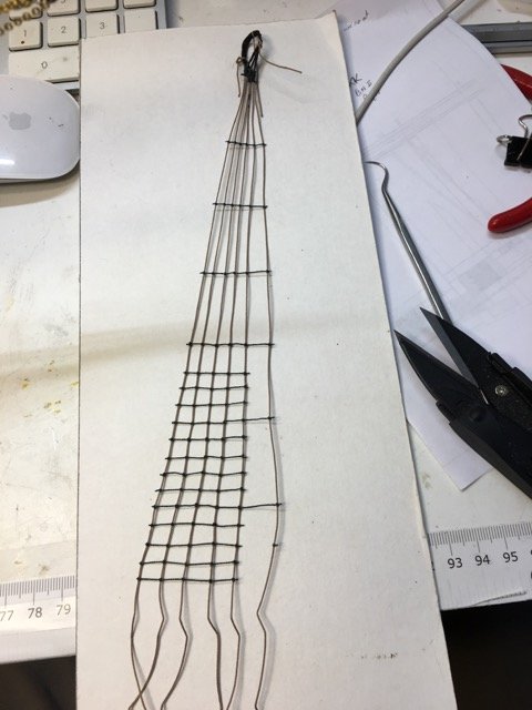
Full removed from the frame.
At this point I decided to try this shroud set out on my Bluenose II. Since I'd already attached the main topmast I had to unattached it.
that turned out to beast (maybe too easy)
Then I draped the shroud set over the main mast
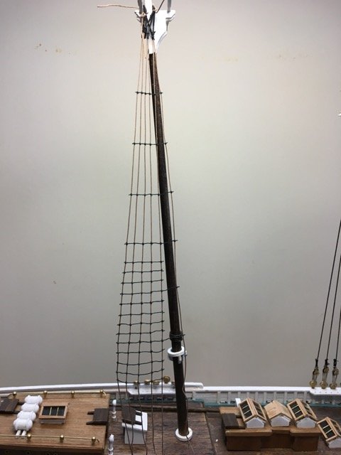
But horrors - it was way too short. Was I not going to be able to use my new favourite tool????
I dug out the plans and laid the shrouds over the image of the shrouds
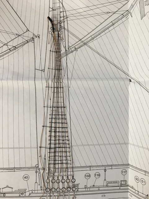
a little hard to see but it looked OK
Even with the extra 1/4 of an inch or so that I needed for the hypotenuse of the shroud-mast triangle I can do this one on the Ratliner - Whew!
That's good in theory (i.e. the plans say I can do it but the ship said I was way out). A bit more measurement and I discovered the problem was in the shipyard - the main mast was too long. I can fix that!
In summary - so far so good. I'll fix the mast, I'll practice tying knots on the edge the Ratliner until I can do it well, and then I'll make the real shroud unit for my ship. I will adopt Ken's solution for the odd-number of shrouds - I'll set up with 6 shrouds but only tie the rat;ones on 5 of them. Once done I'll snip off the 6th shroud (having made sure to seize the 5th and 6th very firmly at mast top.
- Canute, cristikc and CaptainSteve
-
3
-
19 hours ago, Worldway said:
Doug, I'm curious and am probably asking a silly question but does it make a long enough ratline to run from the top of the mast to the dead eyes? Can you adjust the length of them?
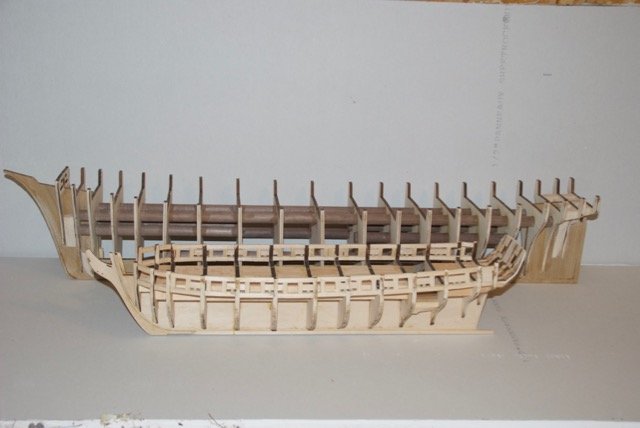
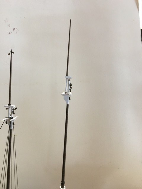
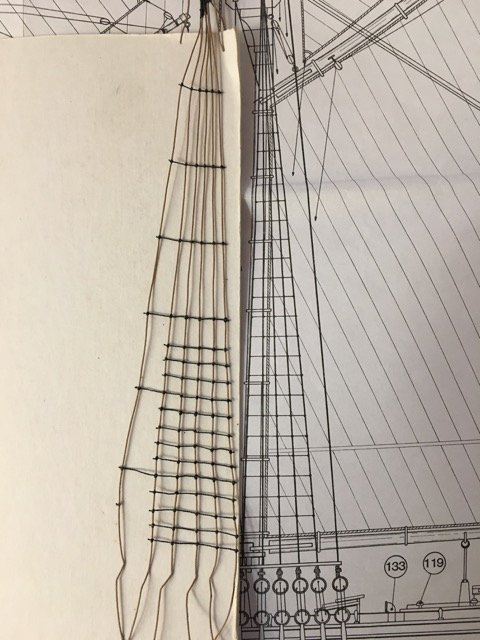
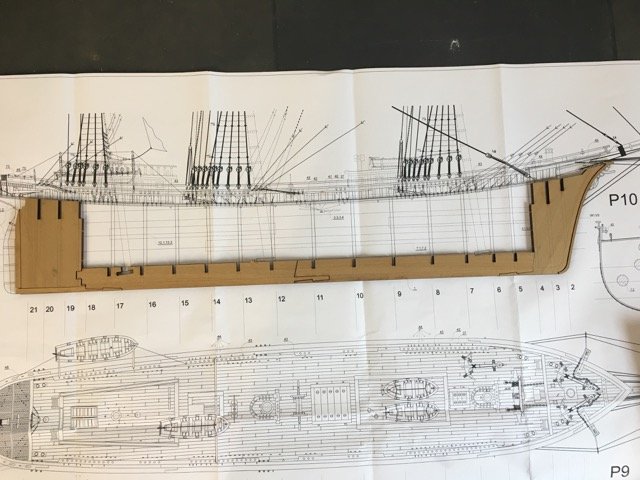
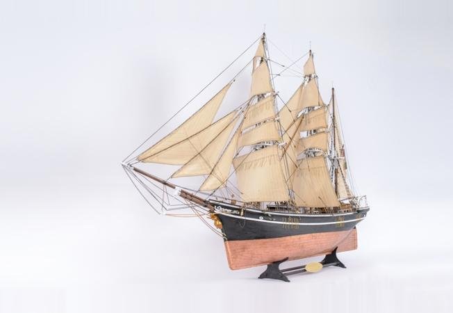
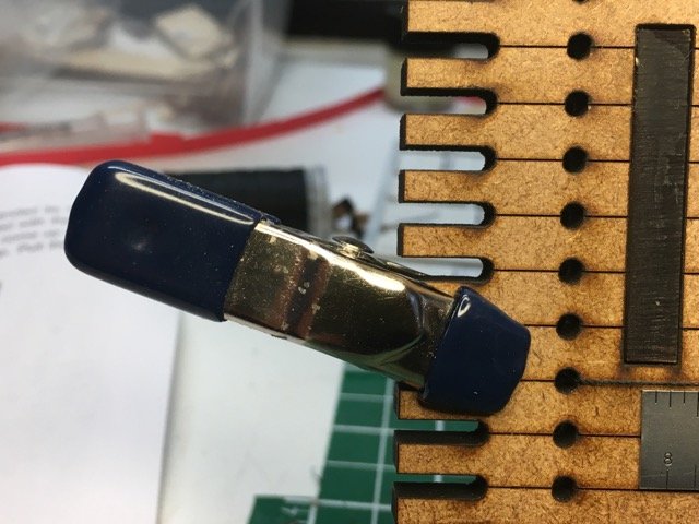
After measuring on 4 sets on plans for 1:64 scale ships I find the Ratliner will handle Bluenose II, Syren, and Stefano. However, even using the extra inch that Ken mentions then it appears that the Prince de Neufchatel main mast can't be handled without some sort of extension. I measure 11+ inches on the plans and when we give Pythagorus his hypotenuse tax the lenthg of shrouds to the sheer pole line is beyond Ratliner.
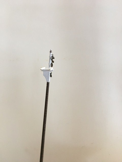
As you can see in this image of the PdN the main mast is quite long compared with main topmast.
I'm glad that the Ratliner will handle 3 out of 4 of my kits.
- Canute, CaptainSteve and mtaylor
-
3
-
On 2018-01-09 at 12:15 PM, Estoy_Listo said:
I'm more inclined towards working boats, but I can see why you're enthused about this build. It looks great.
Thanks. "It's fun to have fun ..." - Dr. Seuss
One might claim these were working boats - just wouldn't want that work myself! Are you currently building a boat?
-
Welcome Derek, David and Don to da D club - Doug
Stefano Guild - sounds like fun! I'm not usually a joiner but I'm in!
-
I can't seem to be happy without a hull to plank. I hope I'll feel that way about rigging some day - if I ever get to rigging one of these little beauties.
")
-
Derek, The frame itself has a maximum shroud length of 10-1/2" to 11". Thats plenty for my Bluenose II from mast top to deadeyes. Are there 1:64 scale kits with longer shrouds??? That really is my question #1 above - I don't know because I don't have much exposure - although I do have some plans I can look at to see for a small sample of ships.
There is a different version of the Ratline for larger scale models - I don't know their maximum though.
Your question asks about top of mast to deadeyes - if you mean very top of mast then I'm sure the answer is no - Do you need to go to the very top of the mast???
- mtaylor, Canute and CaptainSteve
-
3
-
Ken, Thanks for the rapid response. I'm sure my knot tying problem will disappear with practice - thanks for the suggestion.
I understand the the reason for the 3 configurations of the col for different scales - I just wanted the reader to be aware that scale mattered. I'm lucky since most of the kits on my list are 1:64 (or 1:63 in one case!)
The drilling of the custom space holes makes sense now that you say it. I just have this reluctance to drill holes in my tools - I have to get over that phobia!
I thought about the singleton shroud looped back on itself at the mast top level but also trying to follow "normal practice" - as I understand it -
of having the port and starboard singleton's attached at the mast top - like the schematics in Lennarth Peterson's rigging books. Your way will certainly work.
Cotton eh? Oh well have to restock now. I've been purchasing Syren Ship Model Company rigging line which I believe is poly not cotton ???? (UPDATED: Syren Ship Company rope is a blend of cotton and linen - not polyester - sorry I got that wrong!). I thought I might avoid getting my own ropewalk - maybe not.
-
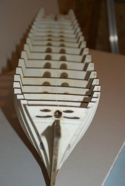
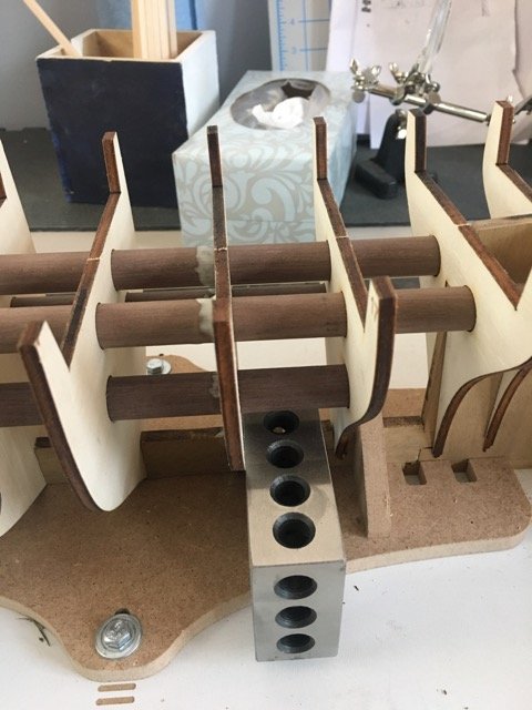
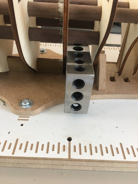
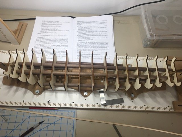
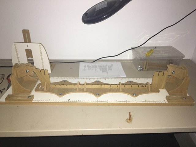
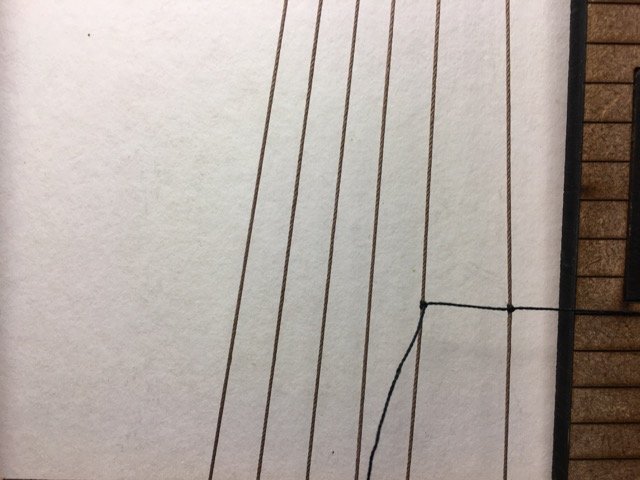
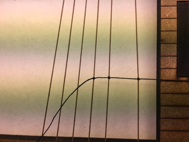
Although the alignment of the bulkheads is controlled by the dowel system, it doesn't guarantee that the bulkheads will be perpendicular to the keel.
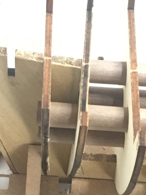
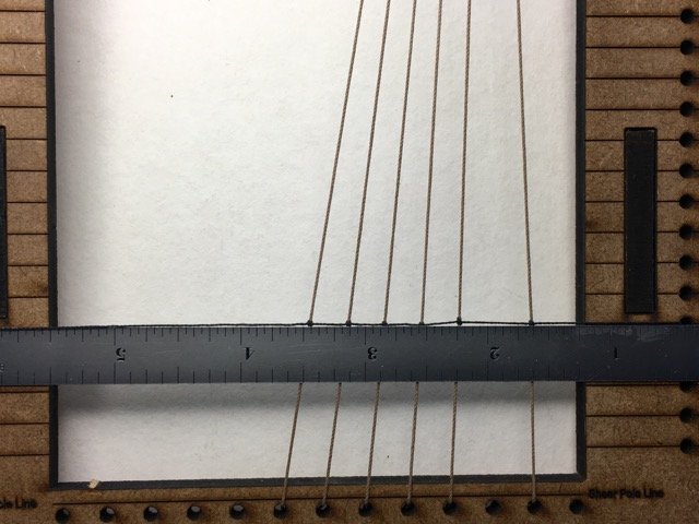
At this stage nothing is glued so we just work through the 21 bulkheads ensuring that everything is squared up.
The vertical line you see above is actually the edge of a steel ruler resting on the dowels and creating a gauge marker that I used to check squareness of the bulkhead against the marks on the building slip. (for the curious only: the X on the building slip just shows me where I lost a hold down nut when assembling the slip)
Glueing is accomplished by painting on diluted PVA glue at each point of contact between the bulkhead and the keel and the dowels. Takes a little while but the end result is a very rigid frame.
- Tom E, rafine and popeye the sailor
-
3
-
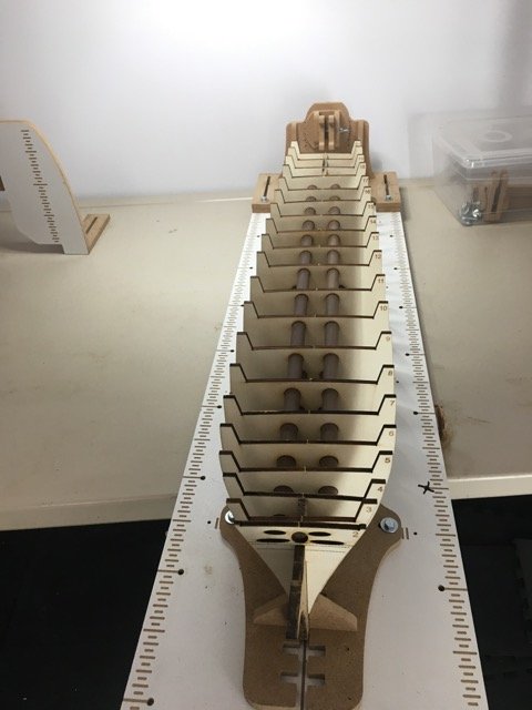
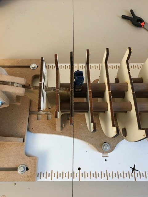
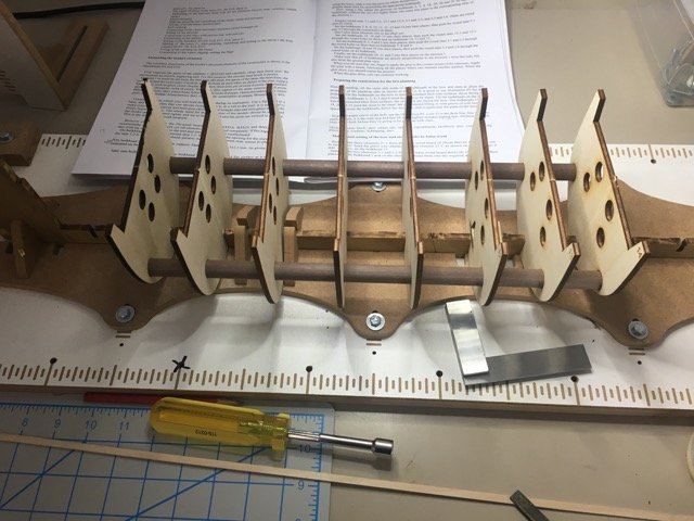
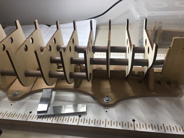
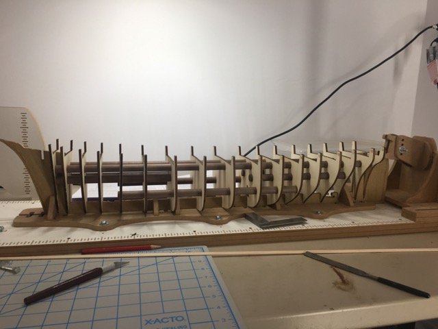
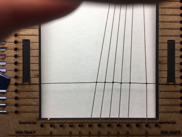
One of the innovations credited to MarisStella is the bulkhead alignment system using wooden dowels.
The bulkheads are dry fitted to the keel and the dowels are inserted through the laser cut holes in the bulkheads. I had virtually no adjustments to make for either of these 2 steps.

-
Unboxing the kit contents was an indication of the challenge ahead - finding room for the build and eventually for the completed model - the hull is 810mm long the completed model will be 1121mm.
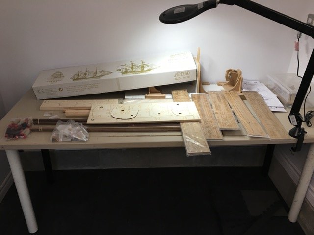
The keel/bulkhead former consists of 7 pieces. Note that the plans are 1:1 wit the model.
In anticipation of this build I purchased a Hobbyzone building slip. I'm hopeful it will prove it's worth. Look here for some other MSW member's experience with it.
- popeye the sailor, rafine and Tom E
-
3
-
Welcome to my build log of the Stefano.
When I saw the 2 current logs for the Stefano I was captivated by the beautiful lines of the ship and decided about a year ago that I would like to try to build it. Now is the time to start.
I'll dispense with the kit contents photos. They can be seen both in Don Robinson's log and in Zoran's log.
The contents of the kit seem to be of top quality. As noted in the other logs the plans are extensive and excellent. There is lots to be learned from building this kit.
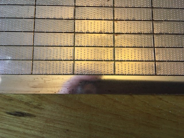
A side note for some of the Syren builders out there who are just dealing with the coppering of their hulls - the Stefano kit comes with photo-etched copper plates with toenail patterns (port and starboard) embossed. I'm not going to miss pounding copper foil when I copper this hull!
In addition to the plans and instructions with the kit I also have every reason to believe that there is very good person-to-person support here on MSW from both Don and Zoran. Don's already helped out a couple of times.
- popeye the sailor, Tom E, zappto and 1 other
-
4
-
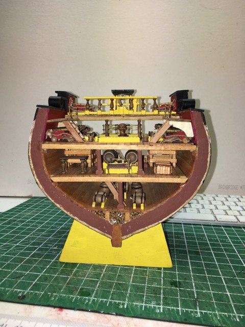
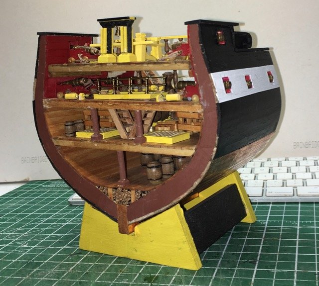
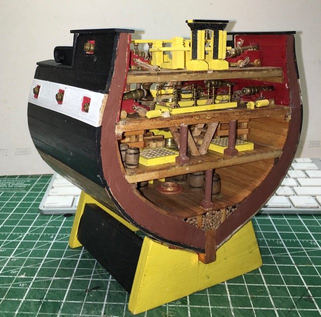
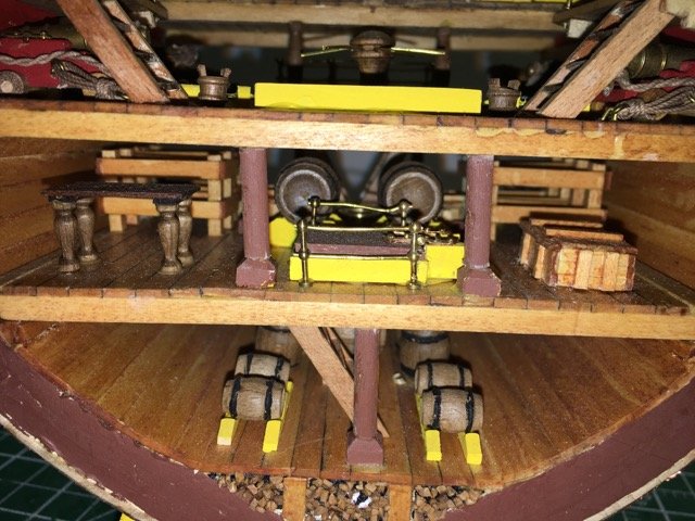
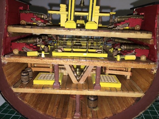
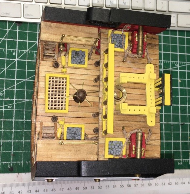
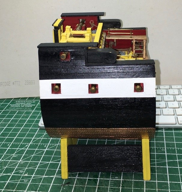
Progress has consisted largely of fittings and cannons being installed.
It is certainly clear that the kit designer was not concerned much about creating a realistic interpretation of the ship with this cross-section. Nevertheless it is still instructive as a model building exercise and I'm having a very enjoyable time with it.
A simple example of the designer's cop out from accuracy is the rigging of the cannons. It would be hard to fire any of these a 2nd time! (You know a year ago when I started this hobby I wouldn't have realized how poorly this arrangement would have been - maybe a year from now I won't build a model with these kinds of glaring errors - here's hoping)
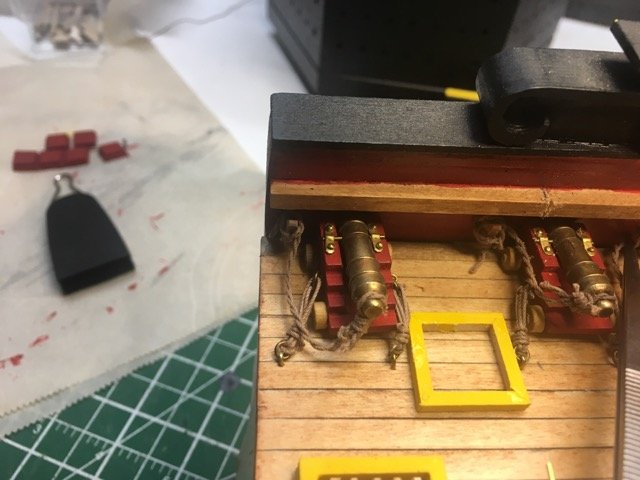
Current state of the build:
-
23 minutes ago, wefalck said:
I think the challenge will be to transfer the assembly to the model ...
You may be right although I gather there are (at least) two schools of thought on that procedure. A great thing about this hobby is that there is lots of scope for personal best practices. Of course one of the challenging aspects of that freedom is finding your personal best practices! A work in process for me!
If I find a solution to problem 2 above I will still have trouble implementing the transfer on my Bluenose II as I have already mounted the top mast!

-
First Impression - Summary and Questions
Positives
- Easy to assemble
- Good instructions for assembly and for usage (a few minor typos)
- Good ergonomics when using - good height and solid stand compared with on mast ratlining
- Helpful design - gets spacing of ratlines appropriate to scale. Correct spacing of deadeyes (at least for my build!)
- Some flexibility is inherent in the design - could do shorter shroud set easily, limited control over shroud spacing by using the "posts" at the bottom of the frame instead of the holes at the sheer pole height, or by skipping spaces.
Negatives
- Tying off the ratlines at the left edge of the frame - may improve significantly with practice.
- Need to purchase different frames depending on scale of model (Model Expo has 3 versions for sale)
Questions
- Is there enough flexibly to accommodate a variety of different ships?
- How to deal with an odd number of shrouds (this is a problem I have to deal with for the Bluenose II)?
- How to deal with the naughty knot problem?
- How easy is it to install the unit on model as opposed to tying it on the model 1st - getting the top row of deadeyes well placed?
So far I like using the Ratliner and I think it should improve the results I can achieve. The show-stopper I am concerned about is dealing with an odd number of shrouds. I need a solution to this issue!
- CaptainSteve, mtaylor and Canute
-
3
-
First impressions. This shouldn't be considered an informed "review" since the I have only once actually put shrouds and ratlines on a modelled that was a 1:96 scale Bluenose II and it turned out pretty badly
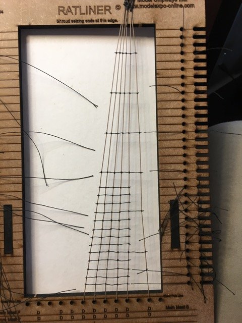
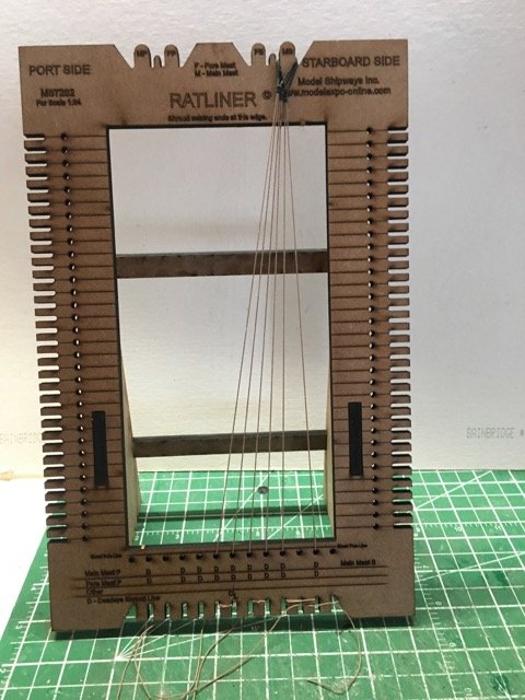
I spent a couple of hours with the Ratliner yesterday. This was just a trial run before I try to use it for an actual set of shrouds.
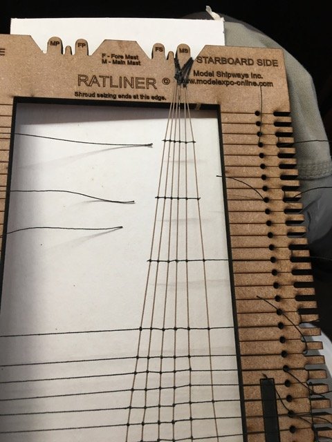
The line for the shrouds was some extra tan-coloured from my Essex cross-section kit. Decent line. The ratlines were black Gutermann polyester thread. Just for fun I served the loop at the top of the shroud pairs.

I'm trailing the starboard mainmast shrouds.
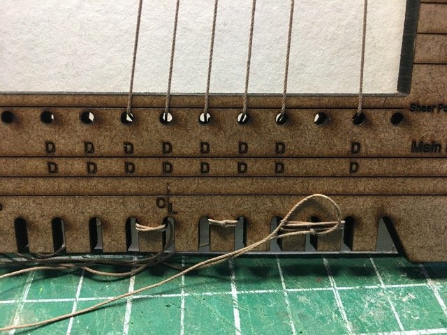
The tie-off at the bottom of each shroud pair. As you can see I also skipped one hole as shown in the examples in the instructions. When I get to the Bluenose shrouds I won't be doing this.
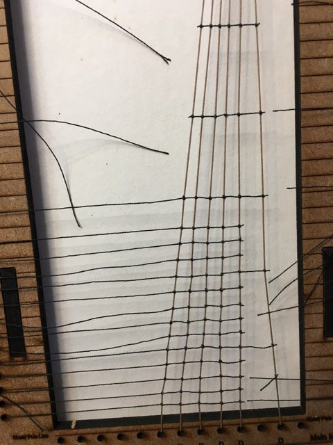
A piece of white mounting board fits nicely behind the front bezel to make visibility of the lines better. The instructions suggest tying every 5th ratline and infilling afterwards. Very convenient height on the desk to tie each clove-hitch knot. After the ratline is tied off on the left edge of the frame I clamped a ruler across to check level and adjusted any knots up or down as required. When Tying each clove-hitch I used tweezers to hold the shroud steady while tightening the knot. I was generally able to keep the shrouds straight but a few I had to adjust the position by tugging on the shroud while holding the ratline steady. It is quite easy to make the adjustments
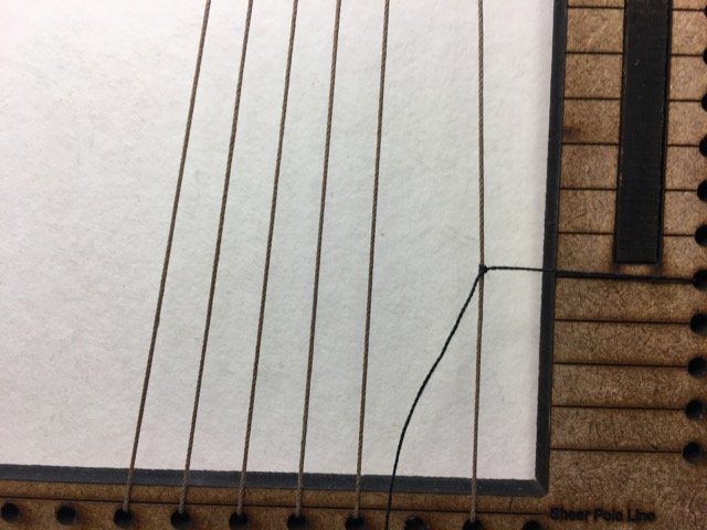
My most challenging issue so far was tying the ratlines on the left edge of the frames. I think this is mainly an operator problem (i.e. me!) but I still haven't figured out a good method. During the work I found the knots would slip or come undone on occasion. I liken the problem to the Christmas ribbon problem - you know trying to tie a knot around the parcel and needing one more hand than most of use were issued. Part of the problem is the "stiffness" of the treads - they like to straight over short distances. Perhaps there is some clever modeller's knot that makes it easier to tie a snug line around a post (I had the same problem trying to belay a line to a cleat at model scale!).
One cheat (when I'd cut a ratline too short to tie a knot at the left edge was to clamp it)
I haven't bothered to do all the ratlines on the test. Current status - knots are glued and drying - tomorrow I'll remove the (partial) shroud set from the frame and see how it feels to handle it. Perhaps I'll mount them on a simulated mast and try to attach some deadeyes. Next post summarizes my 1st impression and questions I still have about the use of the Ratliner.

- mtaylor, Canute and CaptainSteve
-
3
-
I don't know if it makes a difference in fact but the instructions (top paragraph page 13), in reference to the below waterline area, say in
"..... the planking slats are used only to obtain the default width of the hull."
I would think coppering over a smooth area (i.e. no bump due to the 2nd layer of planking) will be more satisfactory as well as more realistic.
-
-
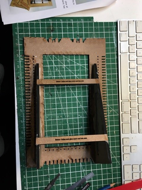
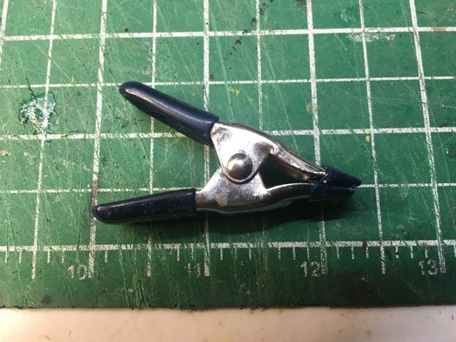
Today was the day that my Ratliner arrived.
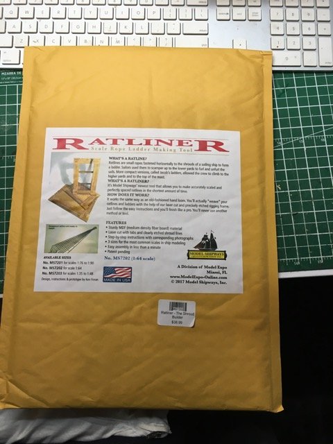
It comes in a padded envelope with a single laser cut MDF board and some stapled instruction sheets (also available online at Model Expo).
2 page assembly sheet
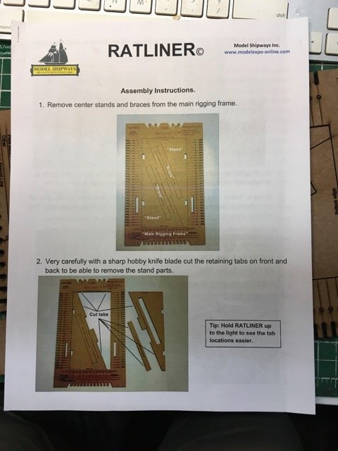
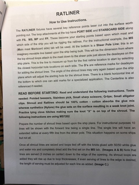
8 page illustrated usage instructions - .
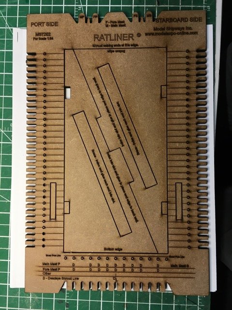
Assembly took under 10 minutes. Now letting the glue set for a day until 1st use.
-
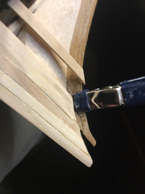
Hi Mike,
I don't know if this will help but my approach is to create a temporary mini-rabbet using a small spring clamp. I also follow Mark's advice to overbend the plank but I don't usually use CA as the clamp will hold it long enough (i.e longer than my thumb can manage!) for carpenter's glue to do its magic.
This works on the stems on the ships I've planked.
-
Barque Stefano by Heronguy - MarisStella - 1:63
in - Kit build logs for subjects built from 1851 - 1900
Posted
The next step is to shape the stern and bow filler blocks. The plans contain 3 views of the stern filler.
Having been raised on the prairies (that's a flat place if you're unfamiliar) I feel challenged imagining 3D shapes from their 2D projections. These filler blocks were no exception. Fortunately the 2 build logs for the Stefano have lots of images to help.
The stern filler is made from 3 balsa blocks. I've taped then together to get a sense of the shaping I had to do.
I did my best to try to create the shapes I saw in the plan.
Don was kind enough to comment on them and convinced me to try harder! There is almost none of the 3rd balsa block that contributes to the final product. I go a little closer with some more sanding and I expect as the stern planking nears the centre of the ship (longitudinally) that I may need to shave a bit more off.
Shaping the filler is only part of the job - it also has to be attached to the frame. As usual with odd shapes normal clamps aren't helpful. Fortunately the elastic bands worked OK.
I also added a couple of small fillers between bulkheads right near the bow and stern.