


Heronguy
-
Posts
863 -
Joined
-
Last visited
Content Type
Profiles
Forums
Gallery
Events
Posts posted by Heronguy
-
-
Thank you Tim. I've followed you love/hate relationship with your build (I know it is a bit strong to describe it that way). I must assume that your standards are much higher than mine - I really like what you're accomplishing with it.
-
Thanks Pat,
By the way, my name, Doug, is in my signature, like yours

I agree that cost/benefit analysis is valid. I don’t assign cost to the learning and the setup phases - is a personal choice but not fair to assume for others.
In in terms of benefits I don’t know how I’d have milled the bracket without CNC. I suppose if it wasn’t an option I’d have settled for the soldered bracket and perhaps even practiced more to do a better job. I was pretty pumped by my milled piece though - that’s worth something for me!
-
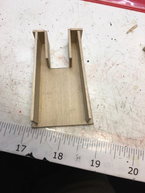
I put the ship's boats aside for a while and went on to the deck furnishings.
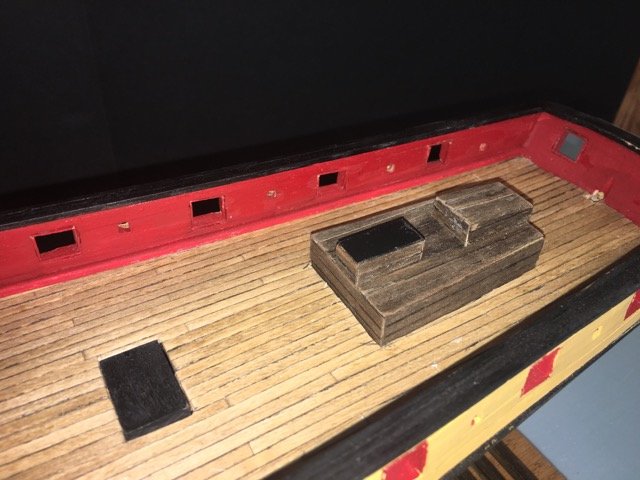
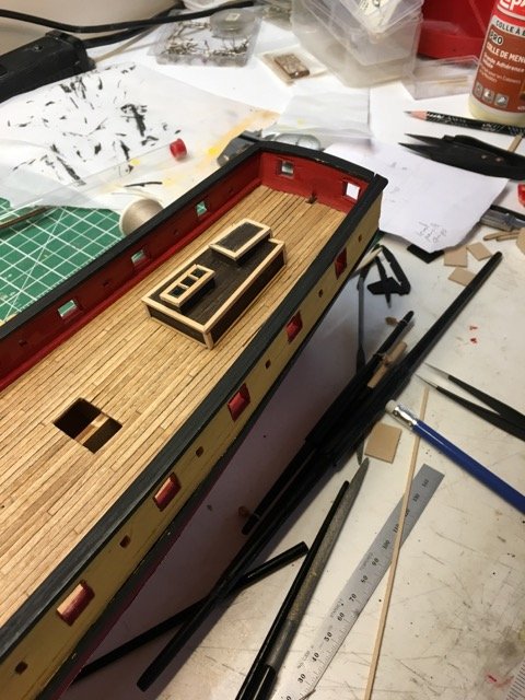
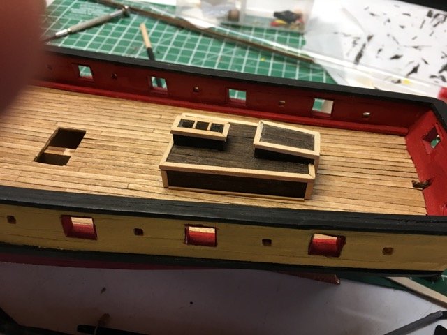
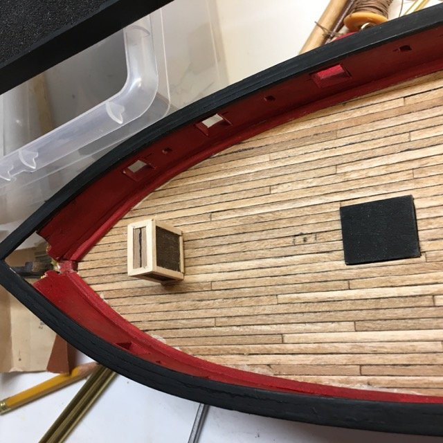
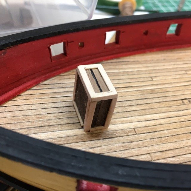
They look so plain (especially the forward companionway) that I am tempted to try to do better. @Tim I. did such a great job on his interpretation of the cabin and companionway in Philip Reed's book (Period Ship Modelmaking - An Illustrated Masterclass) that I will try to do similarly.
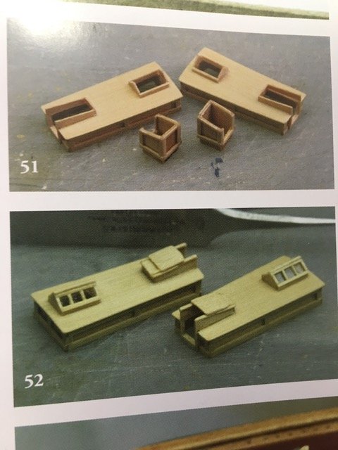
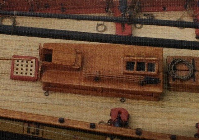
Just started on that process
- GrandpaPhil, rafine, robdurant and 6 others
-
 9
9
-
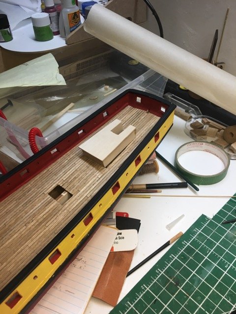
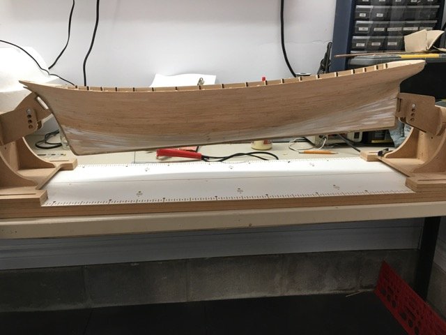
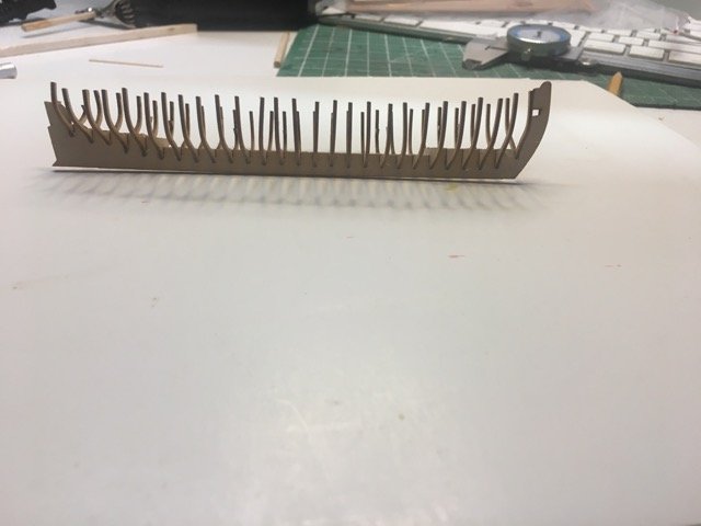
Since the last post I've planked and painted the inner bulwarks and planked the deck.
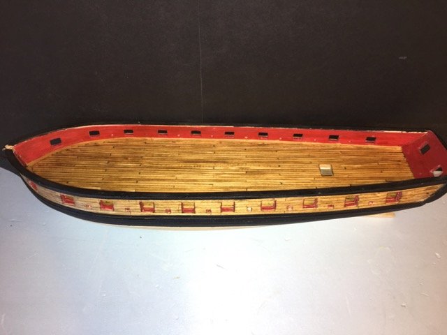
-
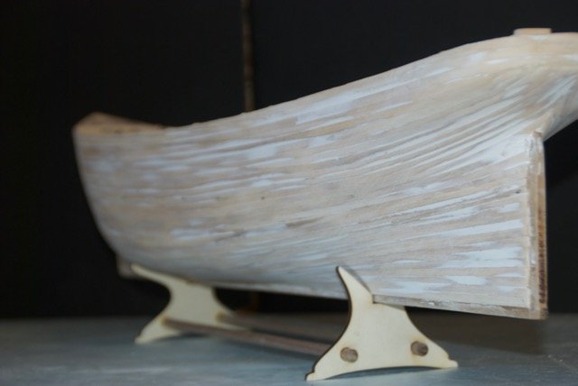
1st planking was completed a while ago and 2nd planking is well underway.
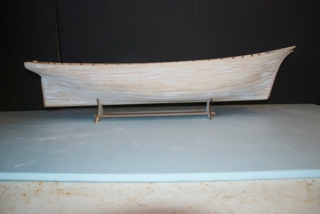
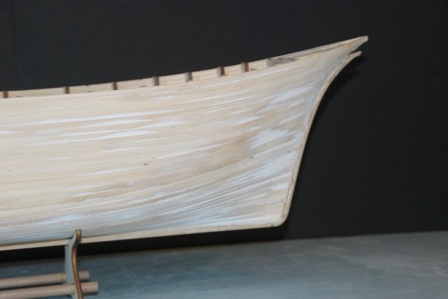
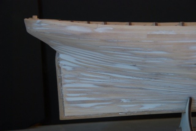
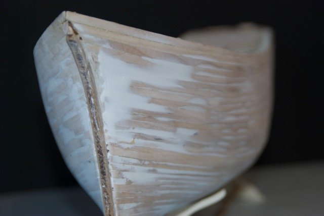
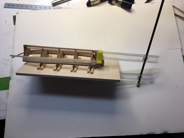
The challenge with the 2nd planking was clamping around the stern where the filler block didn't allow the clamp jaws to rest. Since the filler block will be removed in a future step it seemed far to cut a channel now to provide clamping surface.
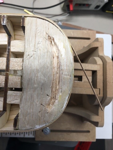
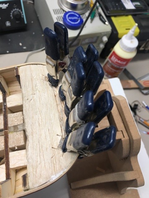
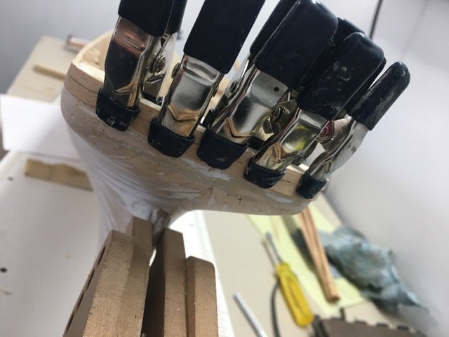
When that wouldn't work I tried elastics to provide some clamping force.
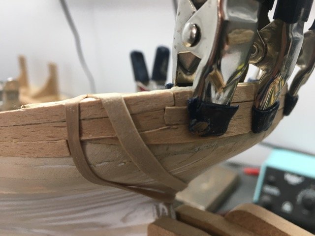
But soon the clamps wouldn't work. On this site I recently read (and of course forgot to note from whom I got the idea) that using a planking iron to heat the plank accelerated the setting of the wood glue. This turned out to be a brilliant idea. I've been using it to attach each of the 100mm planks. It takes about 10-15 seconds for the adhesive to set. It works especially well on the curvy bits. I think the moisture in the PVA glue, when heated, helps the wood to adopt the shape of the surface it is pressed on. I have not used any CA adhesive.
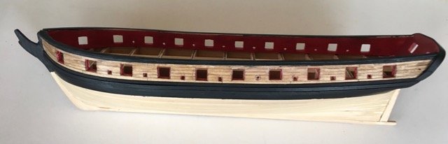
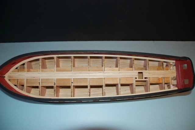
Thank you ????? I wish I could find the post I read to give proper credit. I am grateful! Planking has just reached past the waterline. All the planks so far are full width. I'll shape the ones from here to the keel as required with the likelihood of some stealers and/or drop planks. Below the waterline the hull will be coppered (a 3rd layer!)
- John Allen, rafine, David Lester and 3 others
-
6
-
I'd love to hear how others on this site are using their CNC mills and lathes. I have a lathe on order and although I debated CNC vs DRO for the lathe I eventually decided on the CNC version since the computer interface provide the equivalent of DRO information another seem to me to be opportunities if controlling X and Z axes concurrently on the lathe (I'm thinking balusters for railings for example - I might want to produce many identical ones).
-
Pros and cons of CNC Mill
The advantages obtained by CNC capability on the mill include:
ability to move the cutter in any of the 4 axes simultaneously (e.g. milling an arc)
precise control over movements
ability to reproduce multiple identical parts
the joy of watching the machine do the work
The disadvantages include:
having to specify milling intentions in a very primitive programming language (g-code)
learning curve of the CNC programming language (g-code)
cost of the system
Things I still have to explore:
CAM software for designing parts (I’ve played with FreeCAD and ben frustrated, will try out Fusion360)
Path generating software ( to take CAM model and generate the g-code to machine the part.
Things to be aware of:
There is no magic in the systems at present You still have to know how the part can be milled. You have to specify the order things happen, the tools to use, and you have to know the capabilities and limitation of your particular mill and tools.
-
Last summer I was fortunate enough to get good deal on a Sherline 2000 CNC mill. As a former software developer I was intrigued with the idea of computer control but as a novice ship builder and novice wood/metal worker I thought It would be most likely that I would just use it in manual mode with the hand wheels while I learned some skills.
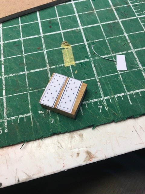
One of my 1st "projects" involved making a weaving accessory for my spouse. That involved a simple pattern of drill holes in a board. The CNC program was pretty trivial but it was cool to stand back and watch the machine do the work (my management credo: "I love work - I can sit and watch it for hours").
But what about ship modelling use. The 2nd project was working on a "riveting Jig" based on the Syren jig defined by Chuck P. More drilling but to tighter tolerances.

This took a lot longer due to learning about milling machine backlash adjustments as I tried to debug a systematic error in the positioning of the holes in the 2nd and 3rd rows.
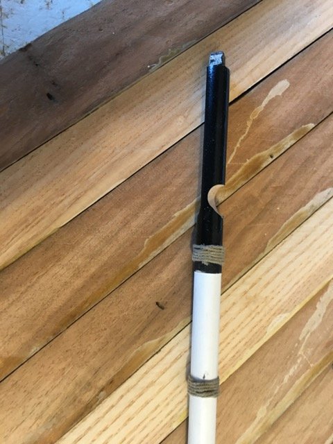
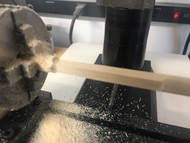
More recently I wanted to square a section of the main mast on my Essex cross section. This was exciting as it was an opportunity to to use the rotary table that came with the mill. This was another little job that I wanted to do precisely and, since I can lose count on the hand wheels quicker than I can turn them, I used the computer interface in manual mode (so the computer drives the CNC steppers in response to individual move instructions - basically gives you DRO capability - no need to count hand wheel turns). I practiced the moves on a spare bit of doweling to be sure before I put the already prepared mast near the cutter.
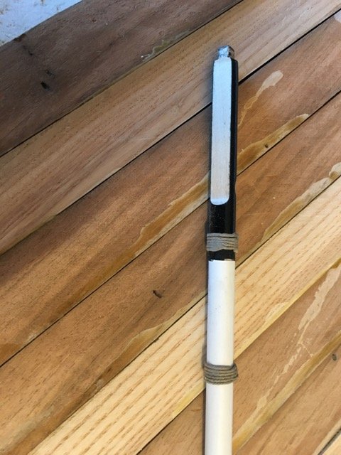
It was going well until I jogged left instead of right! One ruined mast.
To be fair I could have made the same mistake with the hand wheels but the damage would have been minimal. Time, I decided, to write the CNC program to square my mast.
I realize that all of this stuff could be done with the mill in manual mode, but as I said, I love "work watching".
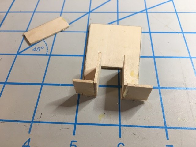
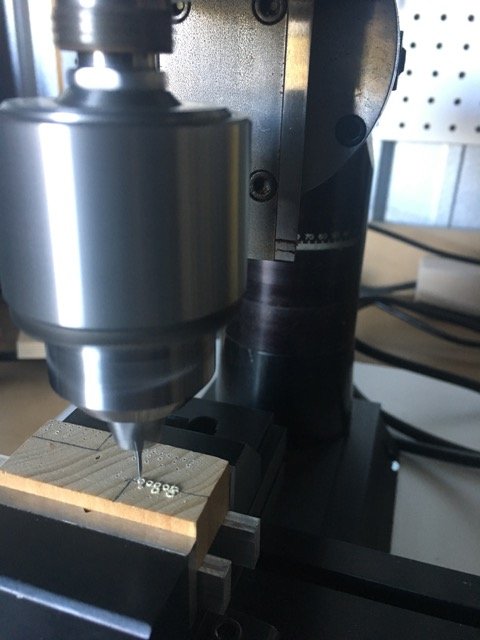
Last week I finally came up with a need for the CNC mill that I couldn't have done otherwise.
The brackets to hold the stunsail booms to the yards (if I've got the correct words ) for the Essex cross-section were horrible(plywood) and making them
out of brass sheet silver soldered didn't turn out too well, so I decided to try milling them.
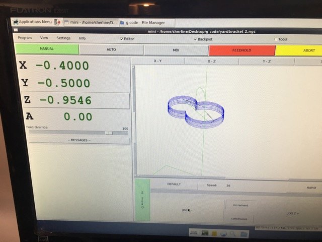
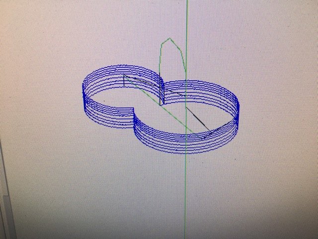
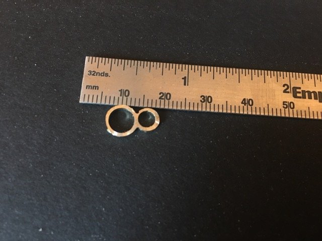
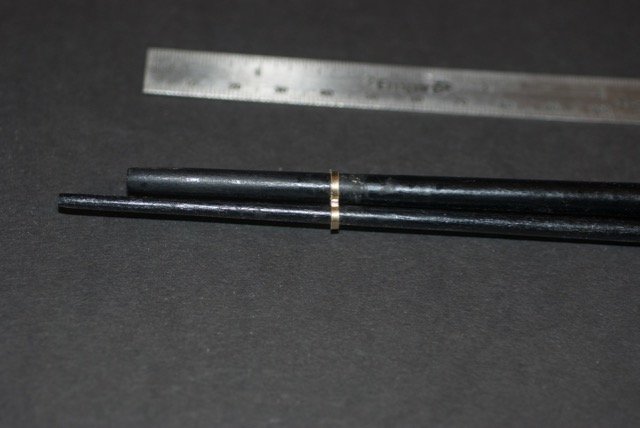
I really like the result. The milling took over 40 minutes the 1st time (with a 1mm end mill I used a really low feed rate). The 2nd 3rd and 4th ones one took 12 minutes and I ramped up fedd rate and depth of each pass. There were 2 small manual steps after milling the basis shape. I drilled the holes for the spars rather than having the end mill do that part, and I flipped the piece over to mill the substrate off freeing the bracket from the stock.
-
-
38 minutes ago, SJSoane said:
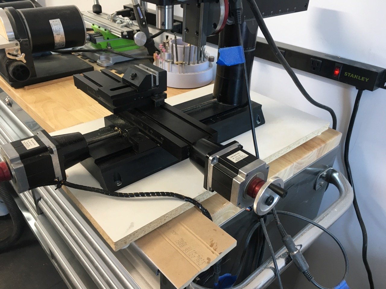
I mounted my lathe and mill on laminate MDF as Doug just showed; nice surface for cleaning up. And after previously experimenting with tools in drawers, I more recently tried mounting them all on the wall, where I could see them all. I prefer this method now.
Mark
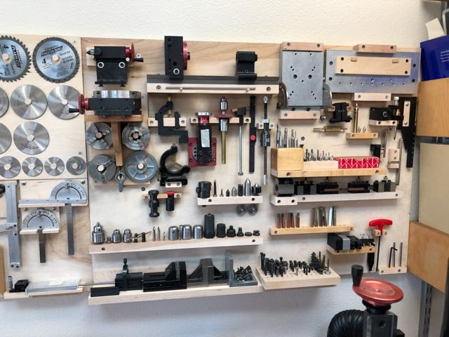
Nice Collection and Presentation!
-
My mill is just mounted on a cheap piece of "shelving". Laminate surface is easy to wipe down. I added rubber feet. I have to move the front one as I've moved the mill onto a roll around tool that is a bit narrower.

- Canute, mtaylor, Landlubber Mike and 2 others
-
5
-
Lot's of choices as usual!
I have a 2000 mill that I bought 2nd hand and have not seen any need to consider the "8-axis" adjustments. As you point out with a tilting table already in your accessories it is even less likely to want the additional "axes". I have read that the re-alignment of the mill after rotating the head has to be done carefully which adds to the time to make the changes.
My mill is inch version as well but I have just ordered the metric leadscrew (and the 18" table) so that it will be compatible with the 17" metric lathe also on order. I have also read opinions that support the longer lathe (see John Earl's comments for one).
I would have accepted the recommendation to add DRO option except that the mill I purchased is CNC and that pretty well removed the need for DRO. I've chosen the CNC lathe package as well.
If space is not too much of an issue I think having both the mill and the lathe will be an advantage to avoid reconfiguration of a single machine.
- Canute, Landlubber Mike and mtaylor
-
3
-
-
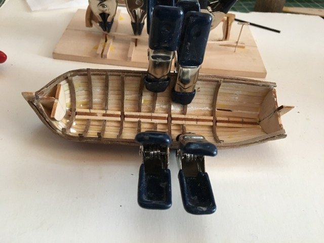
Pushing on with the little boats. I won't use either for the PdN build but I'm taking each a bit further.
I'm now convinced that I can build a Model Expo ship's boat (and I have a kit on order to prove that conjecture). I think I've made enough mistakes on the one's 2 I've built so far that I'm running out of goofs to try out
 .
.
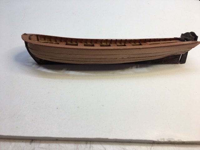
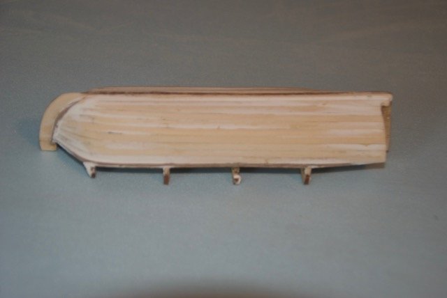
Here's where the "prototype" is at the moment. This one is the 2nd-planked version.
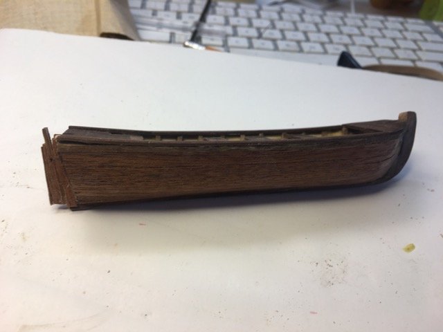
The original Model Expo boat that I was building last year has also come along. I decided to use some boxwood strips that came in a package of miscellaneous pieces from Crown Timber yard for the planking. it was nice to work with boxwood - it was my 1st experience with it. I won't bother taking this little build any further.
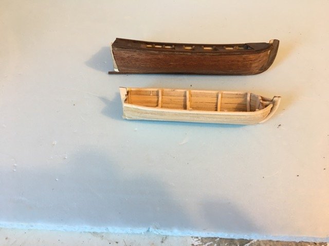
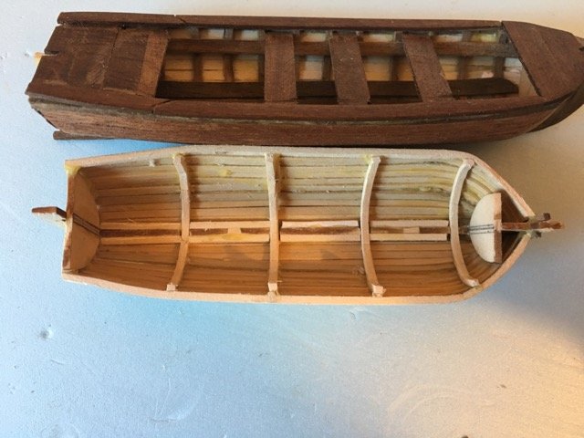
The Dusek's ship boat side project came together pretty well - the planking was a bit more challenging that I hoped so I'll end up filling and then painting the outer hull. I still recommend the kit if you want a little break from other builds. There is still a few details to finish on this build.
-
I have this kit on the shelf. Show me the way!
- EJ_L, md1400cs, popeye the sailor and 1 other
-
4
-
Hi Art,
I'm working through a build of the version you show on the right hand side. I looked at the more recent instruction manual but felt there were too many differences so I continued with the original instructions and John Earl's practicum.
Enjoy your build.
-
Off to a beautiful start! MarisStella kits are good value aren't they - I really like the quality.
-
-
The Dusek's ship boat is a really nice break from the MS boat.
The ribs and keel former went together very easily.
The floorboards are etched onto some thin, shaped pear sheet. Very strong and looks great.
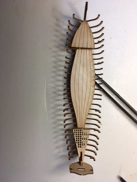
An application of tung oil really brings up the beauty of the wood. The laser cutting is very precise and everything has gone together easily.
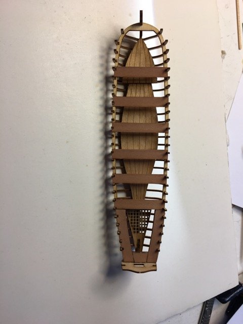
Currently working on the planking. All the strakes are laser cut and spiled.
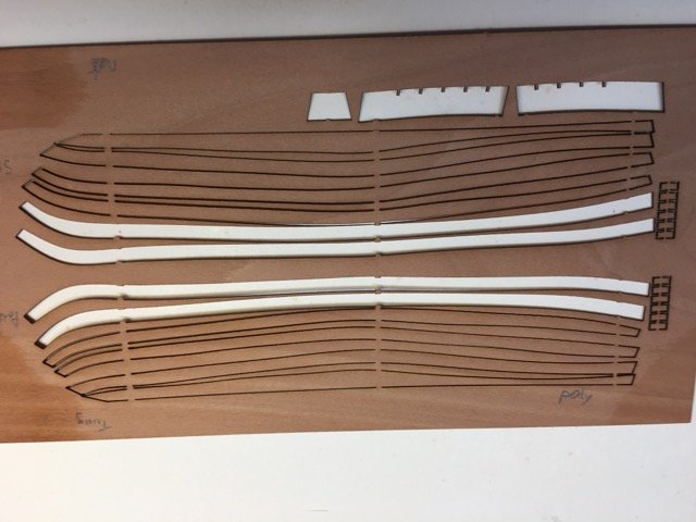
It is still a challenge to get a close smooth fit. I had hoped to be able to finish the hull in natural wood (this pear wood is very nice!) but I think some filler will be required and I may have to paint the hull.
I highly recommend this build and at the price it is well worth it.
-
I've been working slowly on the ship's boat. Although not finished I have made some progress.
As a relief from the frustrations of the MS ship's boat I started a small side project to build the Dusek's Ship's Boat. (€12 with free shipping). I have also gone back the the smaller MS ship's boat to see if I can finish it.
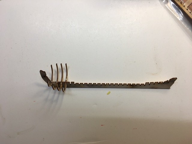
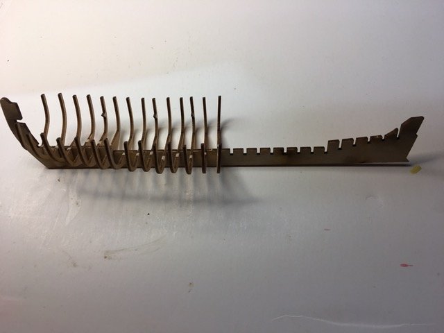
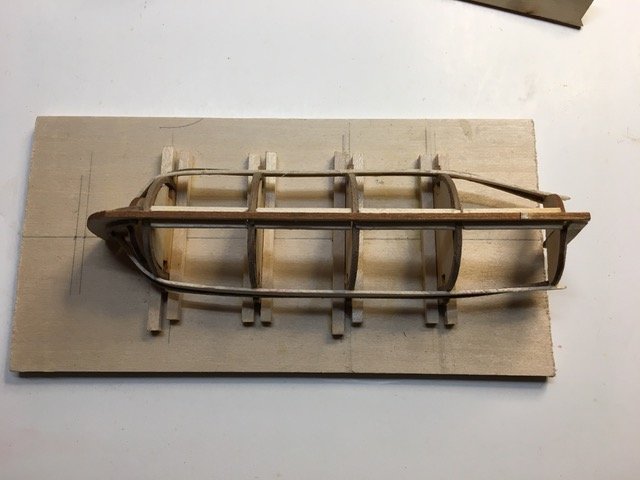
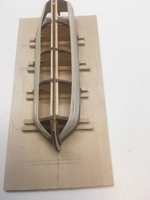
First the 5" ship's boat.
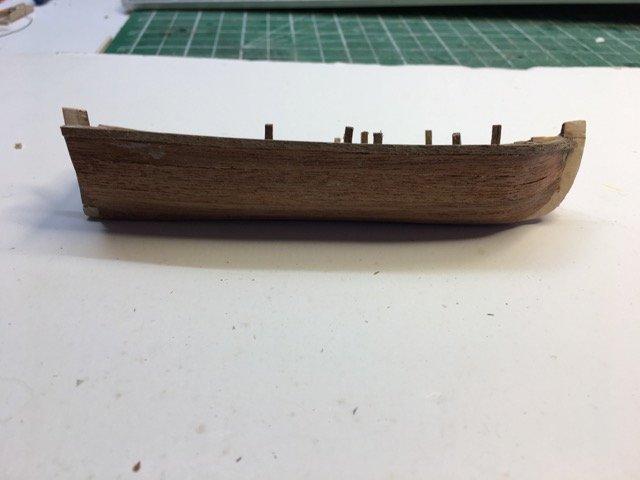
After the ribs were set I added the sheer rail also from walnut.
Notice how far the rail is from the bow bulwark. I just lived with that.
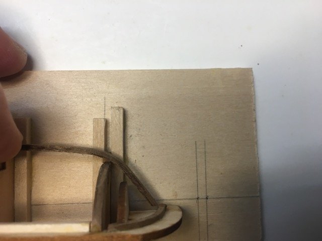
The rails were not very smooth or symmetrical at either the bow or the stern but I just pushed on - too many redo's on this fragile frame are not in my repertoire.
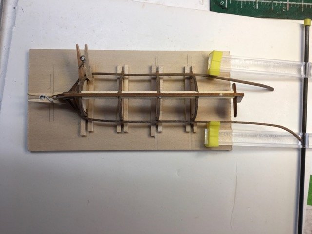
On to planking. I had to do the usual planking job - tapering the strakes at the bow and stern - and find ways of clamping this little guy - mostly finger pressure.
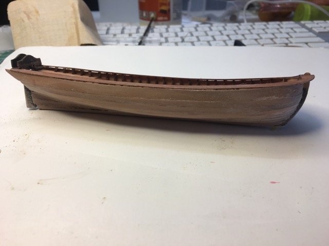
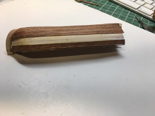
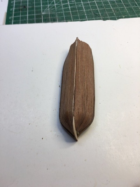
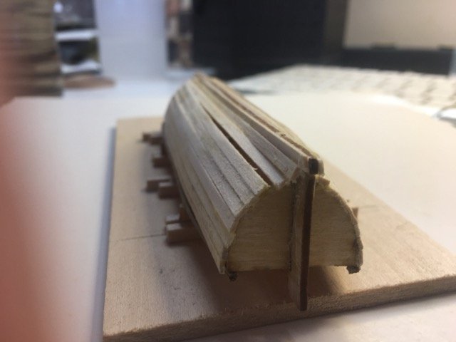
Planking complete but the hull is very thin and still has gaps - I used polyfilla spackling for filler. At least it looked like a boat.
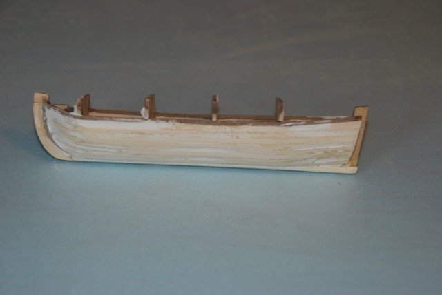
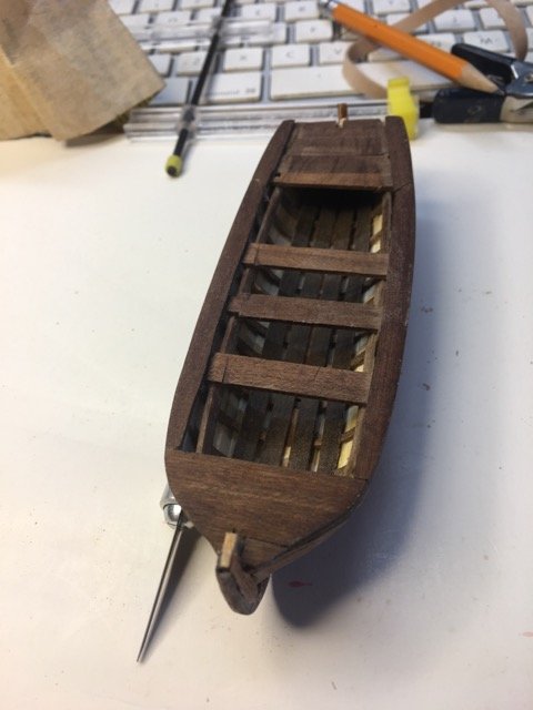
I decided to add a 2nd layer of planking using some leftover wood from the Bluenose II. I'd have been happier to have some skinnier strips but I wasn't going to try to slice them. I think it turned out OK.
I've added a second strip to the sheer rail to create somme overhang outboard, and started to add the rest of the ribs.
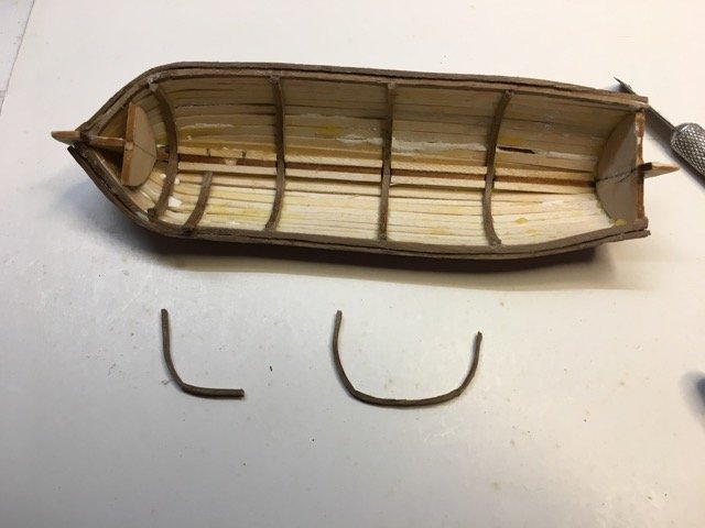
Still to do: Finish ribs, add some floorboards and seats, bow platform and rudder. Then apply some finishes. To be continued.
- popeye the sailor, rafine and Nirvana
-
3
-
-
Quite gorgeous Peter. Great progress.
-
22 minutes ago, Jim Rogers said:
Most frustrating kit in the world.....burned four of them and called “ No Mas” on the basswood. Here is the secret....dump the basswood and get syrene plastic strips the same size. Bends easy.
Thanks for the heads up Jim.
I had to walk away from it a short while ago - frustrated! I take from your comment that it isn’t going to get more fun! Ah well.
-
It will be good to have your observations. I still stumble onto problems when confronted with them - haven’t developed enough experience and insight to foretell them! I’ll get there though.
PdN has become popular. Hurray!
Barque Stefano by Heronguy - MarisStella - 1:63
in - Kit build logs for subjects built from 1851 - 1900
Posted
I'm told its is beech (see Don Robinson's build log). The parts list for the kit says it was to be walnut but it clearly isn't!
The beech is very easy to work with (at least at this thickness - I don't have any other experience with it)