hamilton
-
Posts
1,933 -
Joined
-
Last visited
Content Type
Profiles
Forums
Gallery
Events
Everything posted by hamilton
-
 Wow, so much about my own life has now been made clear!! Thanks for this Jason - much cheaper than a therapist! hamilton
 -
Such beautiful tones in that wood - excellent work - a real beauty! hamilton
- 306 replies
-
- 2
-

-
- armed virginia sloop
- Patrick Henry
- (and 2 more)
-
Hi Dave - just discovered this log. I haven't had time to read through the whole thing (too busy with work!!) but at some point soon I hope to wade in more deeply. Just wanted to say that she looks great and this seems like a really nice kit. When I first started modelling I joined the LSS forum through my build of the Model Shipways AVS. By that time, Bob had stopped actively marketing his kits, and it was my understanding that they were largely unavailable - though it seems that those who built them spoke very highly of their quality, and it seems that he's updated them with some 3D printed materials - very interesting! Anyways, once I free up some time from work I'll definitely be following along here with great interest hamilton
- 306 replies
-
- 2
-
-
- armed virginia sloop
- Patrick Henry
- (and 2 more)
-
Such nice lines on this ship! Well done hamilton
-
Definitely worth it to replace them if my memory of the britannia castings serves correctly.....those guns look really nice hamilton
- 831 replies
-
- 4
-
-
- Armed Virginia Sloop
- Model Shipways
- (and 1 more)
-
Thanks Dave! I certainly do plan on putting in some orders at Crown in the future - I've got a Syren build coming up that I'm thinking of using at least one of his wood replacement packages for just to give it a whirl. To be honest, I'm not sure this build is the one to drop the money on.....not that I "class" the models in this way, but my capacity to obsess is very high already so I'm trying to tone it down.... hamilton
-
Thanks David - I think my anxiety about the planking is less about the method and more about the material! Initially I wanted to replace Mamoli's planking stock for first planking, but it's impossible to find scale strip wood locally milled to metric sizes and the imperial equivalents are just a little too odd to find in real world hobby shops these days (at least where I live) - 5/32 x 3/16, for example is just not a possibility. I also don't want to incur the expense of ordering relatively small quantities online.....so I'm stuck with Mamoli's planking material. I have to make one small adjustment at the transom, where removing the already-installed 1/32 planks is no longer a possibility (using thicker strips for the second planking) but other than that I'll go with Mamoli's material. What this means is that I'll have to add to the supply of .5mm x 4mm strips used for the second planking of the lower hull, since Mamoli supplies only enough of these to plank to the waterline.....I think I have a number left over from other builds, but I need to check.....I want to use copper tape for the coppering instead of the wood tiles included with the kit.... Anyway, back to work! hamilton
-
Thanks Nigel - much appreciated. She's not much to look at now, of course....looking forward to finishing the first planking to get a sense of her real shape. As I prepare for this, I'm noticing all kinds of little flaws, which will need some careful attention....I don't think I've fretted this much over planking a model for a while....It's always possible I'm overthinking it. Last night I ripped the two planks I installed on the forward side of the hull off and replaced them with 1mm thick kit-supplied walnut - a real waste of nice material, but given the fact that I cannot acquire correct substitution strips locally I will have to use it if I want to hull to turn out right.....I'm heading into an extremely busy time at work these next few weeks so I doubt I will have much time at the bench, which is a shame.....but Christmas is coming and I might get a bit of a reprieve sometime in November.......stay tuned! hamilton
-
maybe you mention this elsewhere Brian, but where did you get the swivel guns? they are clearly not the britannia ones included with the kit... hamilton
- 831 replies
-
- 4
-
-
- Armed Virginia Sloop
- Model Shipways
- (and 1 more)
-
So I've been giving it some thought and I think I'm going to strip the planks I laid down last night off the model and start again - thankfully I've not gone too far. My reason is that I think I've been using the wrong sizes of wood stock.....I need to resupply at a local hobby shop and begin again. The main issue is the incremental but cumulatively significant differences in metric versus imperial measures - the material I'm using to substitute for the kit supplied walnut is in Imperial....the width is less of an issue than the thickness....I'm going to invest in some wood strips for each section (bulwarks, wales, lower hull) that are very slightly thicker and then sand to blend where necessary....hopefully this is not too foolish hamilton
-
Hi Simon: I've always been intrigued by this model - looking forward to seeing it come together - with the wood replacements and extra details you're adding it should prove to be real beauty! One quick question - you mentioned in your first or second post that the kit came with a scribed deck - is there no separate decking supplied with the kit? The reason I ask is that I have Corel's Berlin up on the shelf and it comes with plywood decks that the modeller is meant to scribe - this is different from the common method of supplying a thin plywood sub-deck on which individual planks are laid. If Mercury is like Berlin, I'll be interested to see how you arrange the deck planking. hamilton
- 120 replies
-
- 4
-
-
- mercury
- victory models
- (and 1 more)
-
Hi Leo: Thanks for this. I am going to copper the hull, but I'll use copper tape cut into plates - it's much thinner than the plates provided in the kit and it will allow me simply to plank the entire hull rather than trying to cut the second planking off at the waterline. I'm going to experiment with some techniques for weathering the copper when the time comes. Thanks again for the comment! hamilton
-
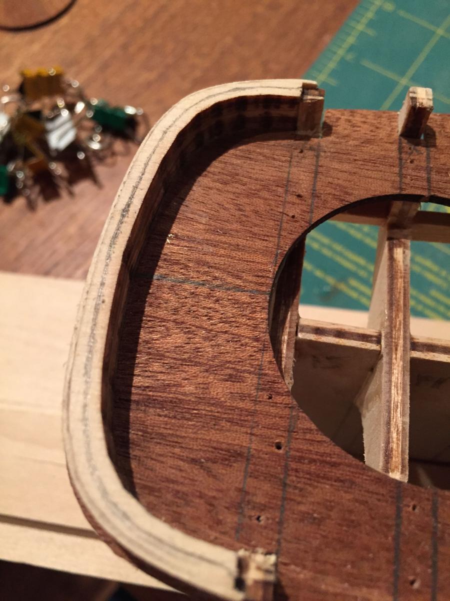
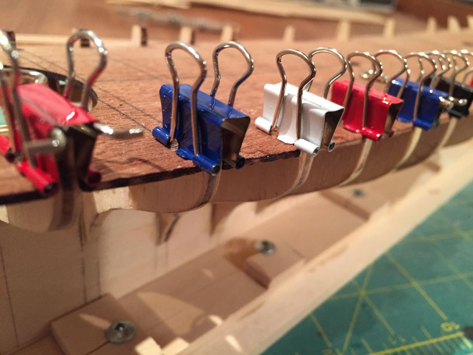
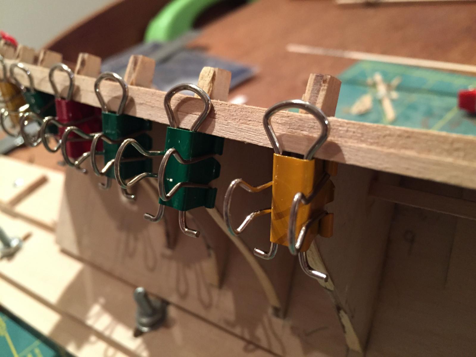
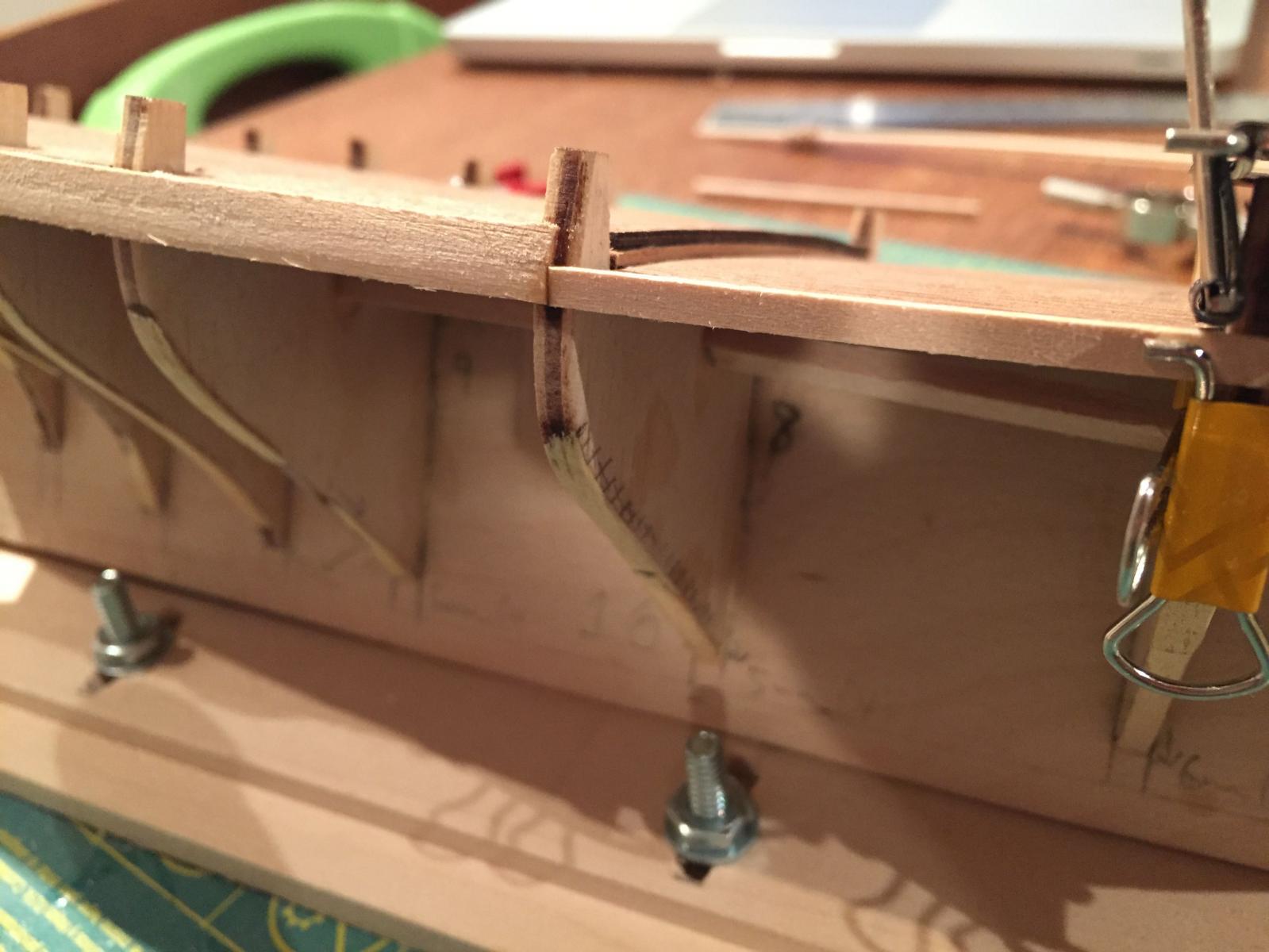
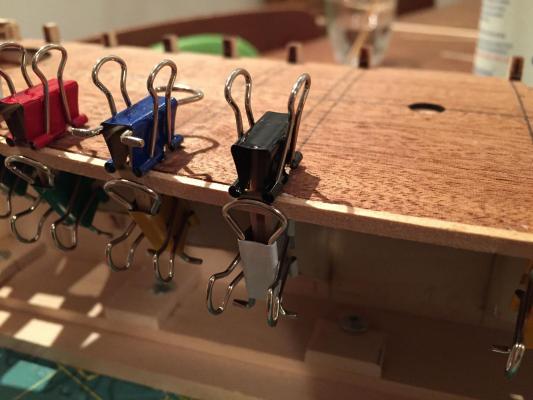
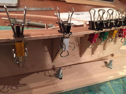
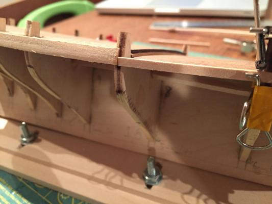
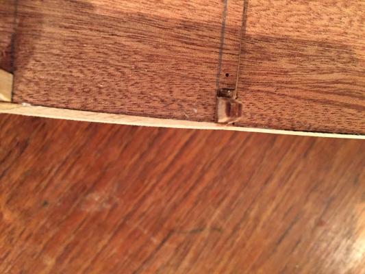
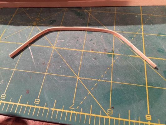
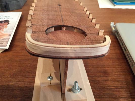
So I did end up making some time for the America this evening. The first part of the night was spent fiddling with the aft bulwark extensions to make sure that the planking will run true. I also marked out the area on the transom piece that needs to be trimmed away. Here it is. I then continued to think a bit more about the planking. As I've mentioned, I'm deviating from Mamoli's approach. The photo on the box clearly shows a defined step marking out the top of the wales and running along the hull at the level of the aft deck. This step disappears forward and the wales blend into the hull planking. I couldn't see how Mamoli's planking scheme would produce this result. Here's what they suggest 1. Lay two 1 x 3mm strakes from the transom forward with the lower edge flush with the top of the aft deck - these are the bulwark strakes. The problem is that there really is nothing to attach these to, since the bulwark extensions will be removed. 2. Lay two 2 x 3mm strakes below the bulwarks - these are the wales. But if these were to run the whole length of the hull, then to create the blending on the image in the box, I'd have to sand down the planks even with the bulwark strakes all the way from mid-ships to the bows. This hardly seemed right 3. plank the remainder of the hull with 1.5mm x 4mm strakes - this seemed fine. I decided to go a different route with steps 1 and 2. For step 1, I first laid one of the wale planks (2 x 3mm) from mid-ships (b/h 8) back to the transom - it had to bend quite a bit there so I thinned it slightly and soaked it to bend around the counter - there ended up being a bit of a kink here which I'll sand out. I used fold-back clips to provide an upper limit to the planks so they would lay flush with the deck. Here are a couple of images I then added a second 2mm x 3mm strake immediately below it with the same run - bulkhead 8 to the transom. The next step was to take a thinner strip - 1mm x 3mm - and ran this forward from the lower of the two thicker strakes forward - this strake is flush with the top of the forward deck. It was then a matter of blending the thicker aft strake into the thinner forward one. It's not perfect at the moment, but with a bit more work i think it'll work ok.... The second planking will have to be done a bit differently, but this is for later....for now, it's bedtime hamilton


-
Wow - the planking finished up great, Brett! It'll be smooth sailing from here, I'm sure! The plastic tube idea is one I've never seen before and never would have thought of - intriguing! hamilton
-
Hi Nigel: Just took a glance through your build log - really great work here! Very clean and sharp hamilton
- 270 replies
-
- 2
-
-
- red dragon
- artesania latina
- (and 1 more)
-
Have fun with it Owen! If you keep a log I'll follow along hamilton
-
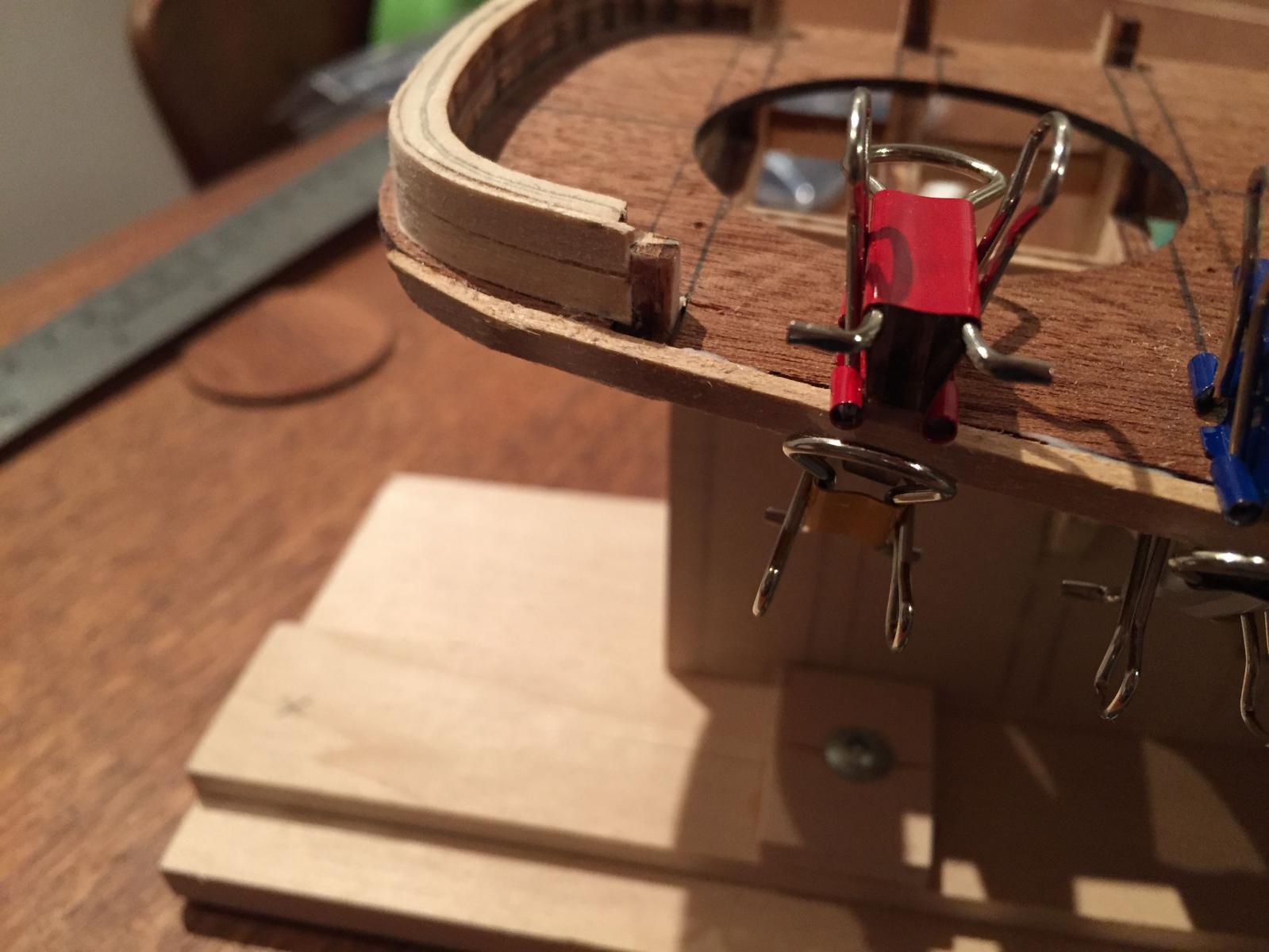
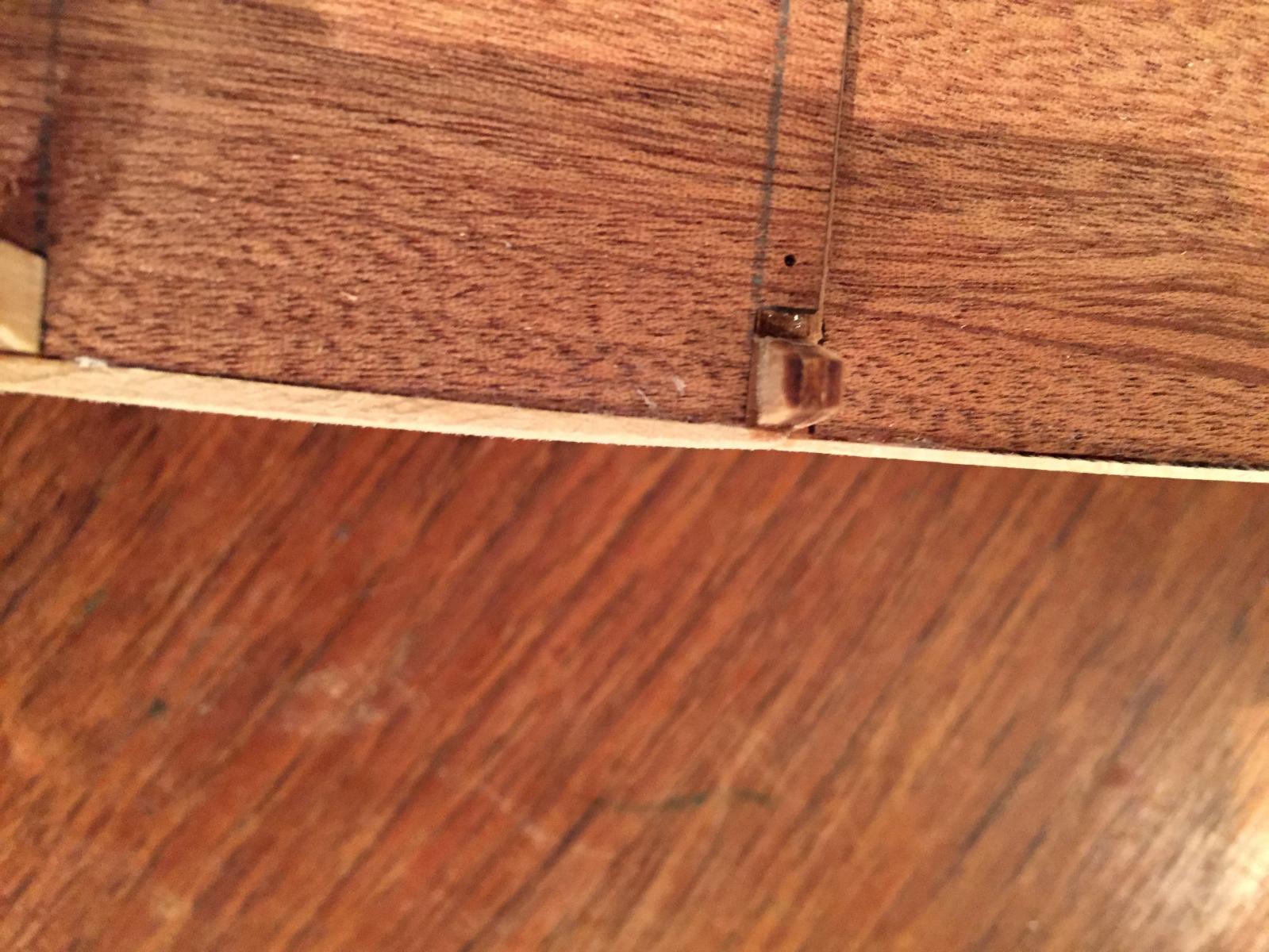
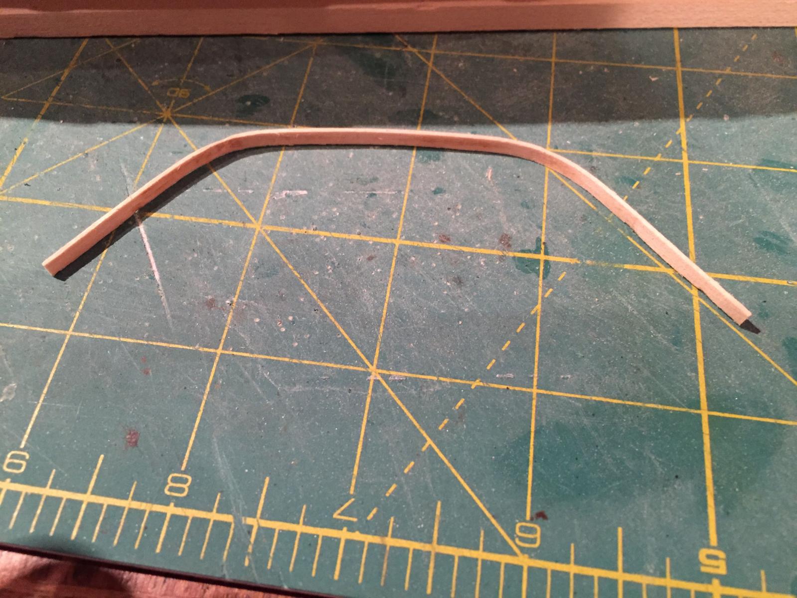
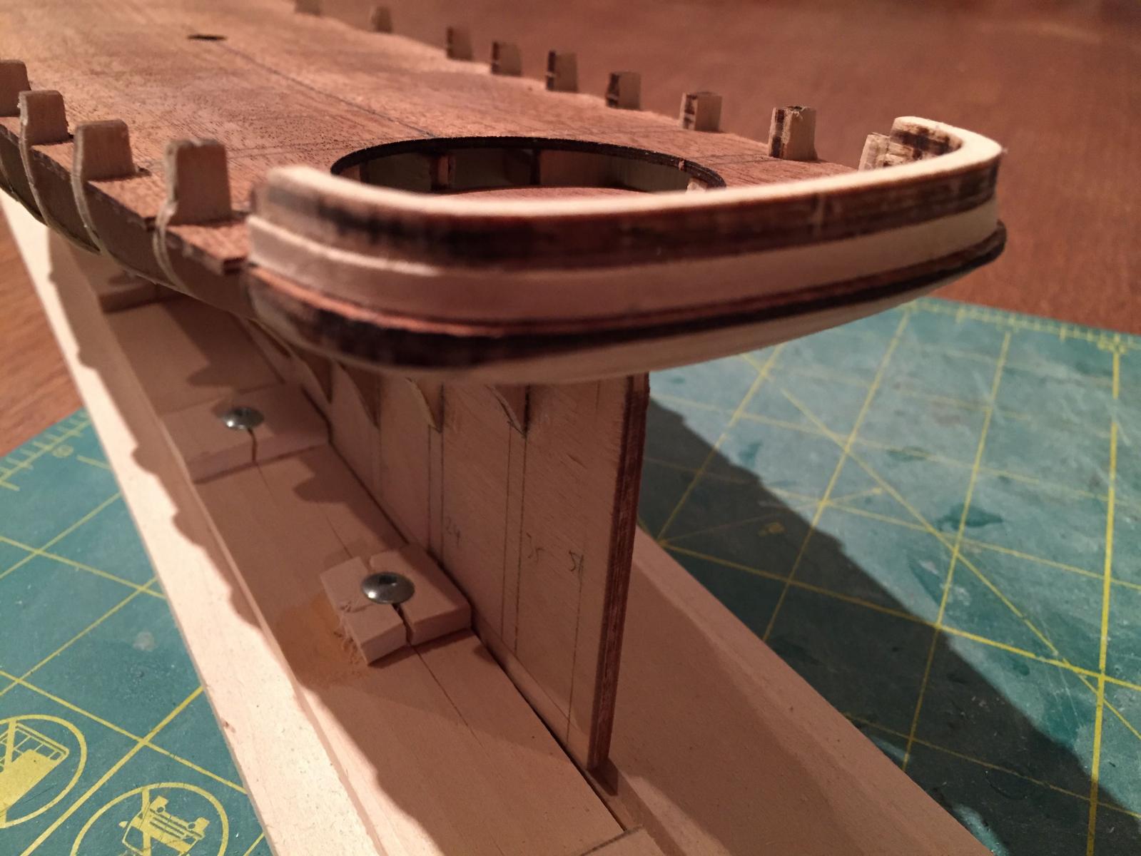
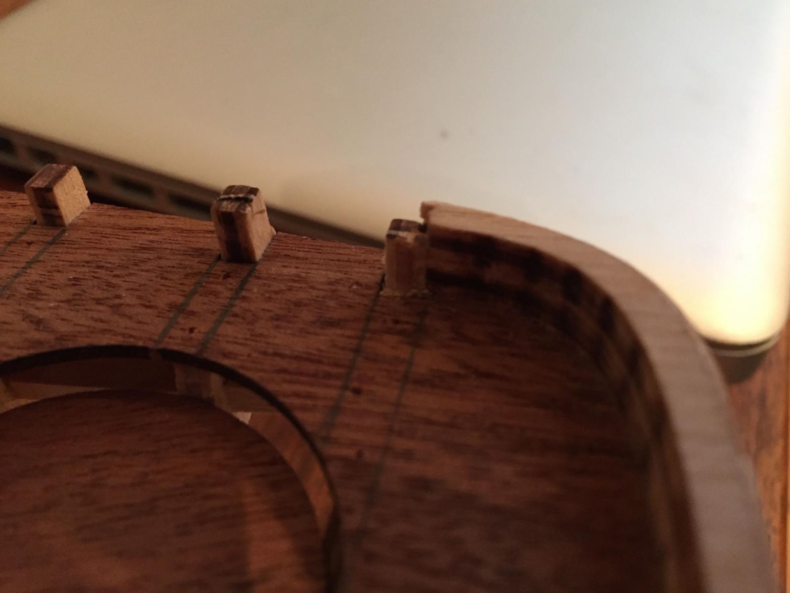
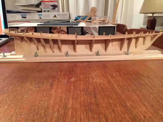
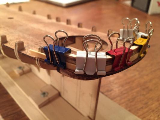
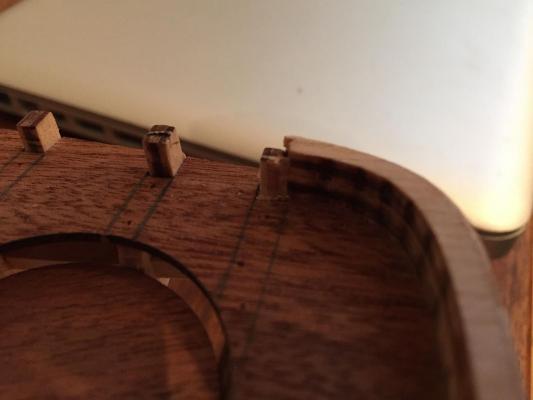
Hello all - a brief update. I've been spending a few minutes here and there fairing and shimming the outside edges of the bulkhead frames in preparation for planking. It's so hard to document this work that I'm not bothering. I'll only say that I tried very hard to be extra careful this time - often I find the fairing process so dreary that I'll rush through it only to pay the price later.....Anyway, hopefully the extra attention pays off! The first bit of planking is also complete - two planks covering the outside of the transom piece. At some point I'll explain how and why I'm going to deviate from the planking scheme suggested in the Mamoli instructions. But for now, suffice to say that I'm replacing the wood for the first planking (and possibly the second, too). Mammal supplies Walnut for the first planking for the wales and bulwarks and thicker lime (1.5mm) for the lower hull. I'm replacing all of this with basswood of various dimensions. Again, I'll save my explanation and itemization for a later update once I've gone into the planking and seen how my approach works (or doesn't!). I used 1mm x 3mm basswood for the two transom planks. I soaked both of them in hot water for roughly 30 minutes and then very gently turned them around the transom piece, using micro fold-back clips to hold the pieces in place. This first photo shows the piece clamped on and being shaped (no glue yet). I left this piece there to dry for about 20 minutes or so and then unclipped it. It sprang back a little and I noticed that the laser burn from the transom piece had stained the basswood slightly - though since this is on the inside, it's not really an issue. Here is it. And here it is installed - sorry for the poor focus! I then repeated this procedure for the second plank. When I clamped the plank to shape it however, I had to angle one of the clips a little bit, which ended up pinching the wood....a minor distortion which I'll correct with some wood filler and sanding. Also - the planks do not cover the entire height of the laser-cut transom piece. There is a space of about 1mm or a bit less that will need to be shaved off. The transom piece will also need to be thinned down to about half its width through the whole piece. I only noticed this aspect of the plans after the transom was installed, so I will have to thin it at a taper from bottom to top. I don't own a good set of micro chisels, otherwise, I'd try to use those to thin it consistently from the deck to the rail......Anyway, here's a shot of the planked transom piece prior to final adjustments (trimming down transom piece flush with planking; filling and lightly sanding the planking for evenness). Finally, it seems, I'll have to make some adjustments to the point where the transom piece meets the extensions on bulkhead 15. First, the extension itself needs to be raised flush to the level of the bulwark planking. This is because the plans show the waterway terminating at bulkhead 15, which unlike the other extensions (which will be removed), will be thinned down flush with the inner edge of the transom piece (I've done this roughly here) to form a bulwark stanchion. I personally think it will look weird to have the waterway end at this point. I think it should run the whole circumference of the deck, including across the stern at the base of the transom. Perhaps I'm wrong, though - I'll need to give it some thought as I approach the deck planking part of the build.....Anyway, here's a photo that illustrates the work to be done... That's all for now - I might get to squeeze another night's modelling out tonight if I can get some work done this afternoon, but I can never bank on having more than 1 night a week these days.....makes progress slow... hamilton

-
Hi Brian: I have to say the rope coils are also one of those things that I often think about doing and then never do! I did them on my AVS some years ago and also for the Corel Flattie and the Glad Tidings. They really help a lot to bring a model to life....I wish I could be as motivated to do them as I am to do the ratlines! Anyway, yours look great! hamilton
- 831 replies
-
- 5
-
-
- Armed Virginia Sloop
- Model Shipways
- (and 1 more)
-
Your build's looking great so far - I have to say I laughed when I saw the clip clamps - I just made a bunch of these on the weekend in the lead up to planking my Yacht America. Looking forward to seeing how your BN comes together hamilton
-
Hi Owen - your M-J looks really nice - can't imagine you'll have issues with the sails on BN. I haven't made a ship with sails in a while (Toulonnaise a couple of years ago, I think, was the last one). On that build I recall that instead of just following the sail plans, I used the plans to make patterns on tracing paper and then tested these patterns against the completed spars - this was really just for the square sails, the forward mainsail, the mainsail and main gaff topsail. I found that the sail pattern provided with the kit resulted in sails that were slightly too big, so I made slightly smaller copies of my patterns and then made the sails from those. (I made copies, if I remember, at 95%, 90% and 85%, but I can't recall which I ended up going with). I would definitely pursue this approach again if making another model with sails. hamilton
-
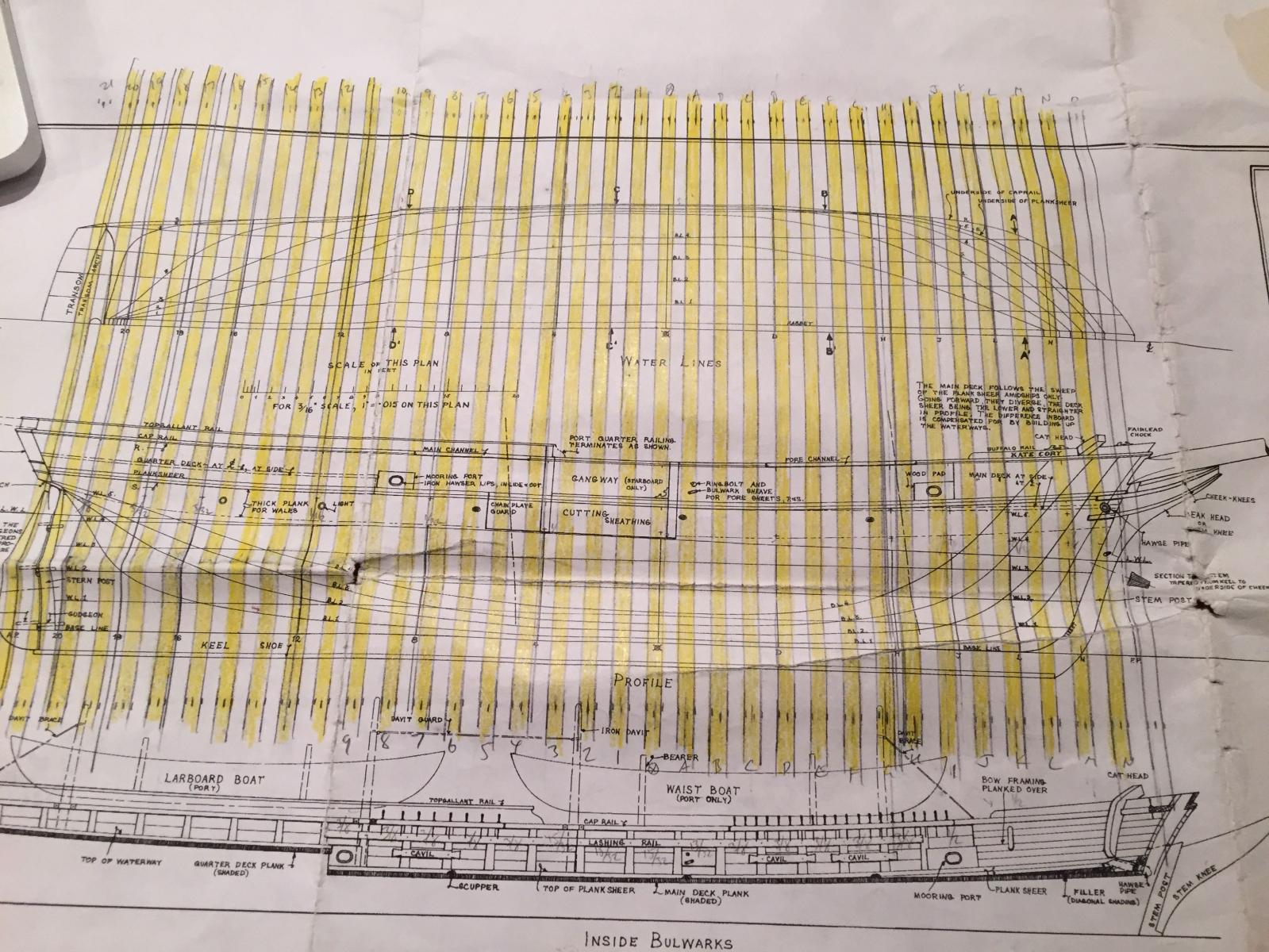
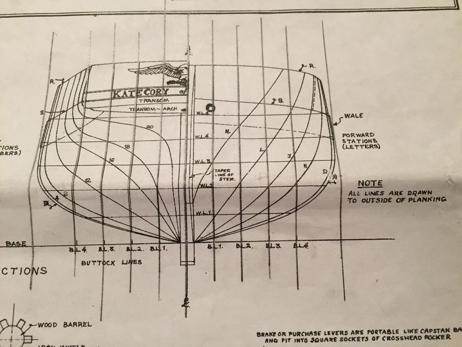
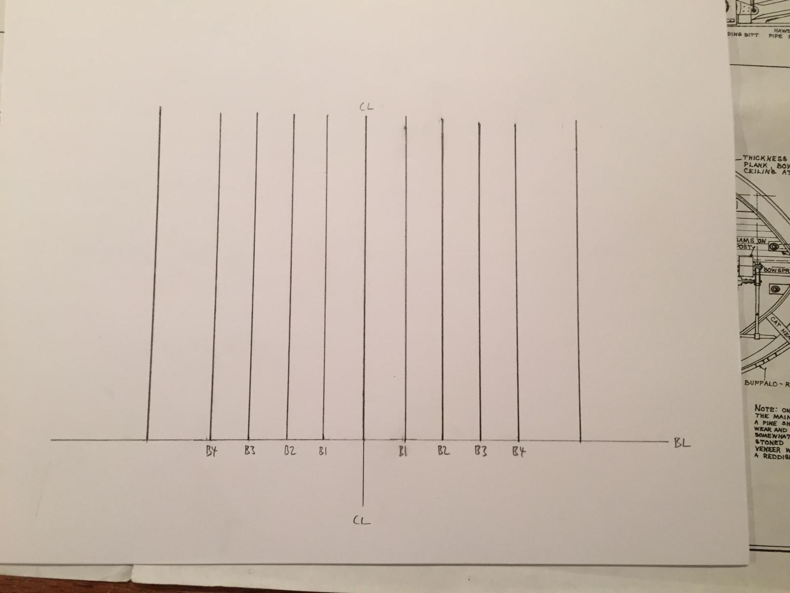
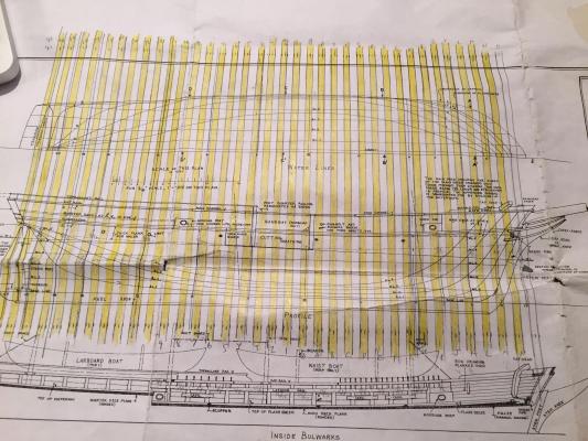
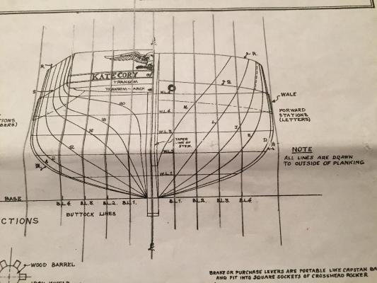
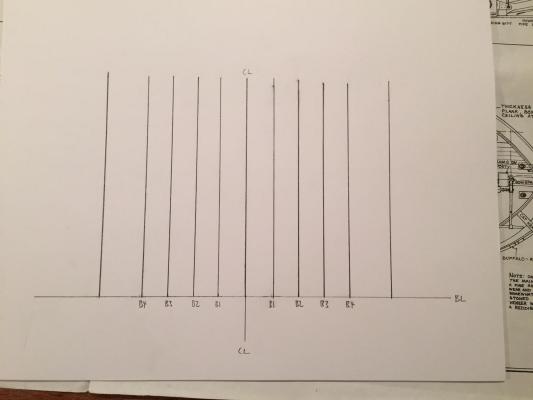
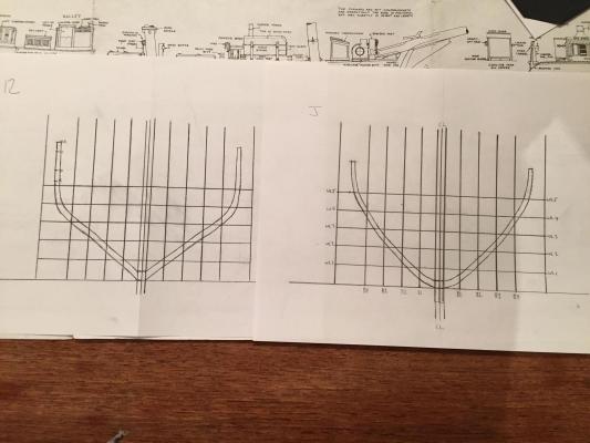
Hi there: I've been building wooden ship models for about 6 years now, and am starting to think about getting into scratch building (despite having several kits on the shelf!!) I've been looking into tools and looking through some of the scratch logs here and reading as much as I can in my few spare hours. One of the great mysteries to me has always been translating line drawings into frame templates. I read the articles here, which at first made me feel like I was back in freshman year trying to figure out what people were talking about. But, as in freshman year, after reading the same and similar things some of it began to click, so I decided to start experimenting with lofting frames from my MS Kate Cory plans, which include all the necessary hull line drawings (body plan, sheer, half breadth). These experiments are not really aimed at producing anything, but more just to gain familiarity with the process. The technique I'm using is derived from Gene Bodnar's Bluenose practicum. I'm posting here and showing some of the process and results because I'm hoping that some of you pros out there might be able to direct my efforts or provide some tips for improving in the craft. Anyway, my first step was to late the frames - this I have to say was largely guesswork - assuming that at 3/16" scale the Kate Cory's frames would be 3/16" wide. Because I'm not interested in actually building the KC as a p.o.f model, I just positioned the frames 3/16" apart. Again, it was more important for my purposes just to locate frames than to achieve accuracy - clearly I would not take this same slap-dash approach on a proper build. Here's the sheer and half breadth with the lines drawn on, followed by a shot of the body plan with the buttock and water lines extended to highlight the grid. I wanted to test out my proportional dividers, so I decided to scale up the lofted frames to 1/4" scale. I set the dividers to 1.5 and then began to reproduce the grid from the body plan on the sheet of paper, using a steel ruler and a right angle ruler to square it off. Here it is in process. Once I had marked the centre line, the base line, the buttock and waterlines and the width and depth of the keel on the grid, I returned to the plans. The stages of lofting the frame were as follows. Frames "J" and "12" were used as samples 1. Referencing the half breadth plan, and using the proportional dividers I marked the distance from the centre line to waterline 1 at the aft edge of the frame. 2. I then transferred this measurement to my grid by placing one side of the dividers (on the scaled up side) on the centreline of my grid where it intersects WL 1 and placed the other end of the dividers on that waterline out to the starboard side and marked the point on the grid. 3. I did this for all the waterlines. 4. I then referred to the sheer plan and, placing the dividers on the baseline at the aft edge of the frame I measured up to (first) the deck line and (then) the underside of the cap rail and marked these on my grid at about buttock line 4. 5. I then took these same locations from the sheer plan, and marked them using the centre line on my grid as the starting point - this game me the location of the outside edges of the deck and the rail. 6. I then connected all these lines into as smooth a line as possible, defining the outside of the frame. 7. I then made another assumption, that the moulded dimension of the frame at the rail would be (at scale) about 1/8" and at the keel about 3/16". These, again, were meant just to give me a basis for my practice rather than to achieve any accuracy. I marked a point 3/16 up from the bottom edge and 1/8 in from the outside edge of my drawn frame at the rail and tried to draw a line as parallel with my first one as possible. This gave me an approximation of a frame. Here are the results of the evening's efforts.... Anyway, I don't know if this gives those of you who really know how to do this stuff enough to go on, but I would love and appreciate any feedback, commentary, suggestions, constructive criticisms or pointers that you may have to offer. Sorry for the lengthy post. Thanks in advance and happy modelling! hamilton
-
I'm thinking of the Echo cross-section as my first p.o.f build - my list of Christmas presents just keeps getting longer!! hamilton
-
Thanks Owen! She was a lot of fun to build, even at this small scale. It took a bit of work to make the adjustments to bring the model more into line with the ship (which I think MS represents more accurately at 1:64). For example, Amati only includes one (thread) bobstay. I added a second and made them from fine chain. The belaying plan on Amati's kit is vague to say the least. The MS plans are very clear in this regard. Anyway, I don't have a build log for the BN, unfortunately. If you keep one, though I'll be sure to follow along and please feel free to send a PM if you have any specific questions or I can try to address issues for you as they occur to me..... I can't recall if sail material was included in the kit - but I can tell you that if it was, I replaced it. Though it's not scale accurate, I prefer to use a slightly heavier and tea-coloured muslin than the thin, white stuff provided in most kits (though it can be dyed). I find the thinner stuff just very difficult to work easily in the sewing machine, many of the mysteries of which still elude me....The kit plans do provide sail patters, so it's easy enough to transfer them to the cloth and sew the seams, etc. There are some tutorials on sail making on the NRG resources page http://modelshipworldforum.com/ship-model-rigging-and-sails.php Good luck with the kit and as I say I'll follow along if you start a log here hamilton
-
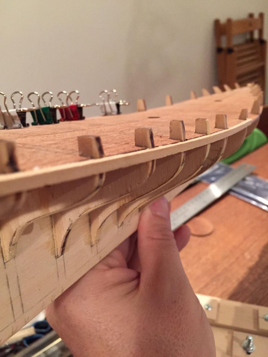
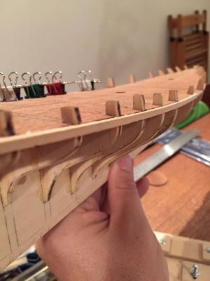
Hello all: The starboard side is now faired. I used one of the thicker strips of planking (2 x 3mm) to test the run of the planks - I thought a stiffer plank might show up areas in need better. I had to do quite a bit of shimming in the aft part of the hull and white a bit of trimming forward. One confusing element is that in the relatively short span between bulkhead 4 and bulkhead 3 the hull sharpens quite a bit. I'm used to bluffer bows so my instinct was to fill in the gap, but I had to stop myself, remembering that this is a racing yacht! Anyway, on to the port side at some point - tomorrow's the big turkey dinner, so it won't likely be until next weekend.... As I was fairing the hull, though, I did pretty much make up my mind to alter the order of the planking as laid out by Mamoli. The instructions advise the builder to first "install" the two bulwark strips (1mm x 3mm), and then plank downward from there, beginning with 2 thicker (2 x 3mm) strips that end up getting thinned down and blending into the thinner hull planking at about mid-ships. This approach was really confusing me, since the bulkhead extensions, onto which you would think to glue the bulwark planks, are to be removed. So effectively, the bulwark planks would be attached to nothing. Hard to conceive. So here's what I've decided to do. I'll start with one of the thicker planks at the stern, with the top edge flush with the sub-deck, so I can actually fix it to the hull. I'll run this plank up to bulkhead 8, which is where the step between aft and fore decks is located. I'll then install a thinner (1.5mm x 4mm) plank below this first one, running it to the bow. I tested this a bit using clamps to fix the first plank in place and discovered that the top of the second plank will be flush with the fore deck - exactly where I want it to be. Once these are set, I'll plank up the bulwarks edge gluing the planks to the ones already installed.... Even writing this down I can foresee a couple of possible issues with my alternative, but why not give it a shot? I can always remove the planks and start again if need be...I'm in no great hurry, after all.... Bye for now - I'll post more photos once I start putting the planks on hamilton
-
The rope coils look great! Really bring her to life! hamilton
- 831 replies
-
- 3
-
-
- Armed Virginia Sloop
- Model Shipways
- (and 1 more)