HOLIDAY DONATION DRIVE - SUPPORT MSW - DO YOUR PART TO KEEP THIS GREAT FORUM GOING! (Only 13 donations so far - C'mon guys!)
×


hamilton
-
Posts
1,931 -
Joined
-
Last visited
Content Type
Profiles
Forums
Gallery
Events
Everything posted by hamilton
-
For me it's about diversity - I don't think I've built the same type of ship twice, though this will come to an end soonish. I'm not really attracted to vessels past the 19th century (no offence to those who are!) though I've built a couple of working boats from the 20th (Corel Flattie and Brittany Sloop, Bluenose). Also, as others have said, it's really about what seems to me to look interesting or capture the imagination. I thought I would be more interested in specific historical subjects than I've turned out to be - for me, it's more about the aesthetics of different hull lines and rigs. It's all fun in any case and if someone gave me an Amati Titanic for Christmas it's not like I wouldn't build it! hamilton
-
Just as a follow up - I've been looking into the 1:48 scale bluenose offered through the Model Ship Builder forum. They offer the plans and a practicum for a scratch build (plank-on-frame). Does anyone here have any experience with this version? I have no experience with scratch building, and this would not be my choice for a first build, but I had thought about keeping it as a future option after cutting my teeth a bit with the MS PoF Emma C Berry and (down the road) the Lumberyard Hannah..... hamilton
-
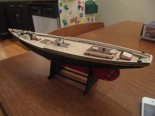
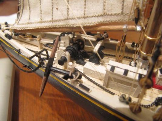
Hi there - I built the Amati 1:100 scale bluenose a while back, but enhanced it with reference to the plans for the MS 1:64 scale ship (scaled down for my build). One thing the Amati kit is shy on is precise rigging and mast/spar fixtures. The Amati kit is not entirely clear on the rig, so the MS plans came in handy - and the Amati kit was cheap enough that I could rationalize the extra purchase. If you don't want to purchase the plans (or otherwise don't care about the rigging), then you can consult one of the many fine bluenose build logs on this forum. Here are a couple of photos hamilton

-
 Thanks Augie! I think I read the same thing in this week's horoscope! Happy modelling! hamilton
 -
Hi Bob: Just catching up on your log - the Hermione's looking great. Your work on the transom is really impressive and the planking is really clean and precise. Looking forward to seeing more! hamilton
-
I'm flattered!! I myself borrowed the idea from another builder on MSW - but because I find myself constantly trolling these pages, I don't remember who! (sorry!!!). I thought the bolts on my keel clamp would end up disrupting the planking at mid-ships, but it turns out that it will be ok. Just to be safe, though I will likely file down the ends of the bolts (or simply invest in shorter bolts!) prior to planking. I'm happy not to have to make a building board/keel clamp every time I start a new model!! In other news, I've started fairing the frames and I can already tell it's going to give me headaches. A couple of the bulkheads really need filing down (4 on the starboard side and 14 on the port, e.g.), while others need a bit more shimming. These are the kinds of issues that seem to show up most obviously once everything is in place - a lot of elbow grease to be expended over the next couple of evenings...... I'm also starting to wrap my head around the planking. It's going to be a bit tricky if I follow the order of things as Mamoli has laid it out....I may deviate from their suggested system of planking and follow what feels more natural (and easier!) to me - or I may try out the system they recommend and see where it starts to break down.....anyways....I don't think I'll be starting the planking for another week or so. Work remains nutty and I can really only dedicate Saturday evenings to modelling......a shame, but the mortgage is not going to pay itself! Happy Thanksgiving to my fellow Canucks! hamilton
-
Hi Byron: She's shaping up nicely. A word on Corel kits - yes the instructions are poor, to say the least, but I've built several Corel kits and I hardly ever used the "instructions" anyway - the plans are all the instructions you need and usually Corel's plans are well done - clear and easy to follow. In many Corel kits I've built there is a parts list at the end of the instruction booklet, and sometimes rigging tables. I found these extremely useful as well. My first step in a Corel build is to go through the parts list and then locate each part on each of the plans its shown on - takes some time, but it's a good way of studying the plans and familiarizing yourself with the model. As I go, I write down the plan sheet number(s) that the items appear on beside the items on the parts list. Have fun with the Endeavour! I've really enjoyed the Corel kits I've built (even the Greyhound, which required a huge amount of bashing), and I imagine the Endeavour is no different. hamilton
-
Thanks a lot Greg - I've actually already ordered Volume 1, which I'm very excited to read. Like Brian, this kind of project is some way off for me, but I'm happy to invest the money in bits and pieces here and there as I work up my courage - looking forward to reading through the first volume! hamilton
-
Hi Nick: Just catching up here - she's looking great - your deck furniture looks miles above what I was able to achieve on my Phantom. hamilton
-
Hi all: I'm not sure if this question is addressed elsewhere, so sorry if it's a repeat (I searched under a few things but came up empty....) Do the first two volumes in the Fully Framed Model series contain plans? Or are there only drawings and photos scattered through the book - I'm assuming no plans (given their availability through Admiralty models and the (former) NMM, but though I'd ask - it has been noted elsewhere, and I'll repeat it (meaning no offence) that it would be nice to see some information on the contents of Vols. 1 and 2 on the Seawatch website....for the interested but not committed buyer.... Thanks hamilton
-
Thanks for the words of encouragement Danny and Daniel - I may try another one of these in the future, but for now, it's nice to be working at a larger scale again! hamilton
-
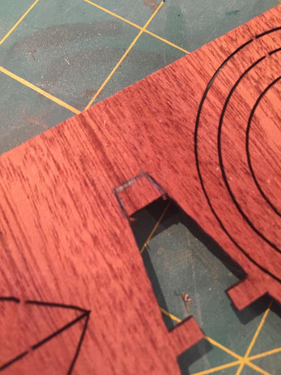
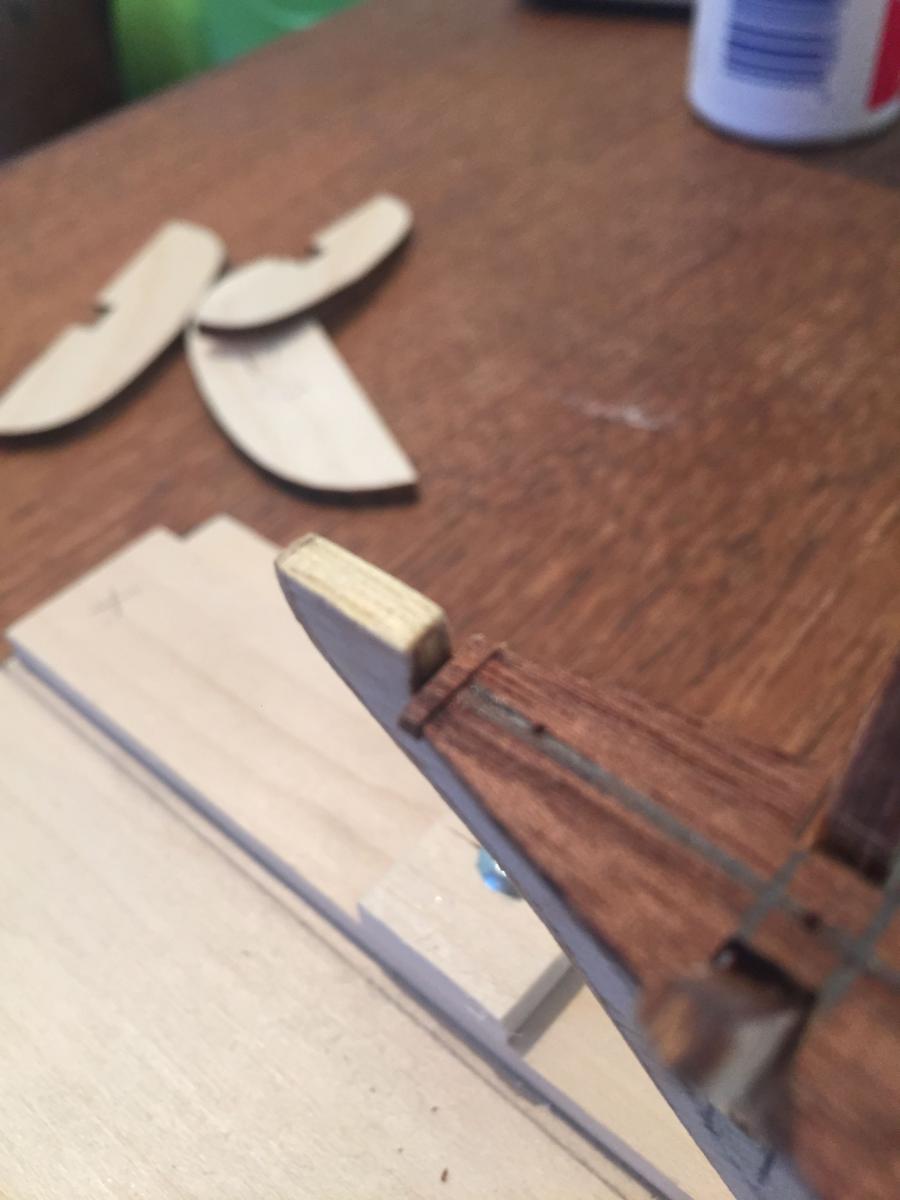
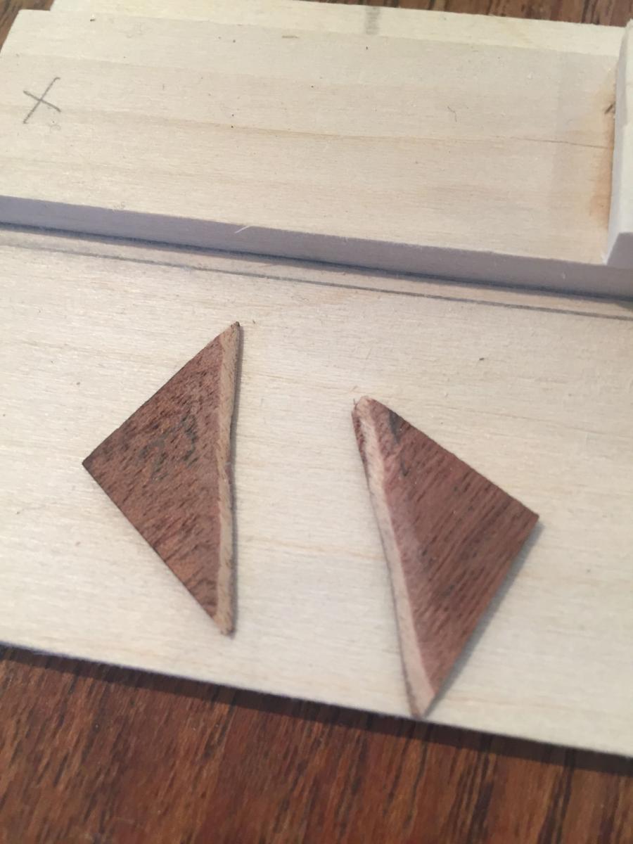
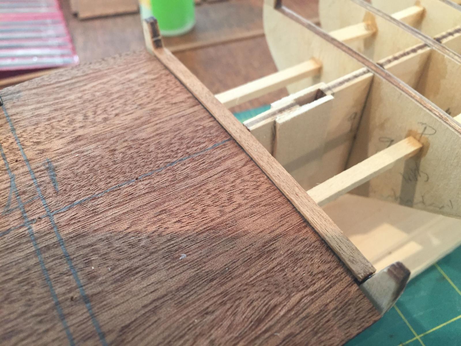
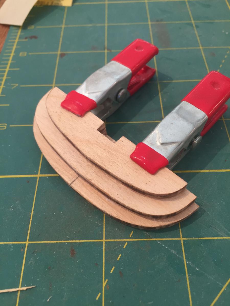
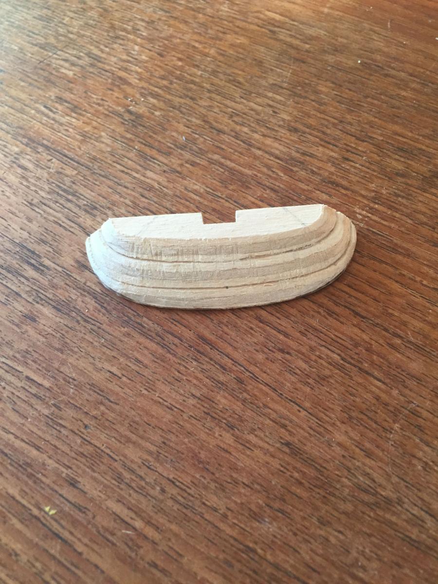
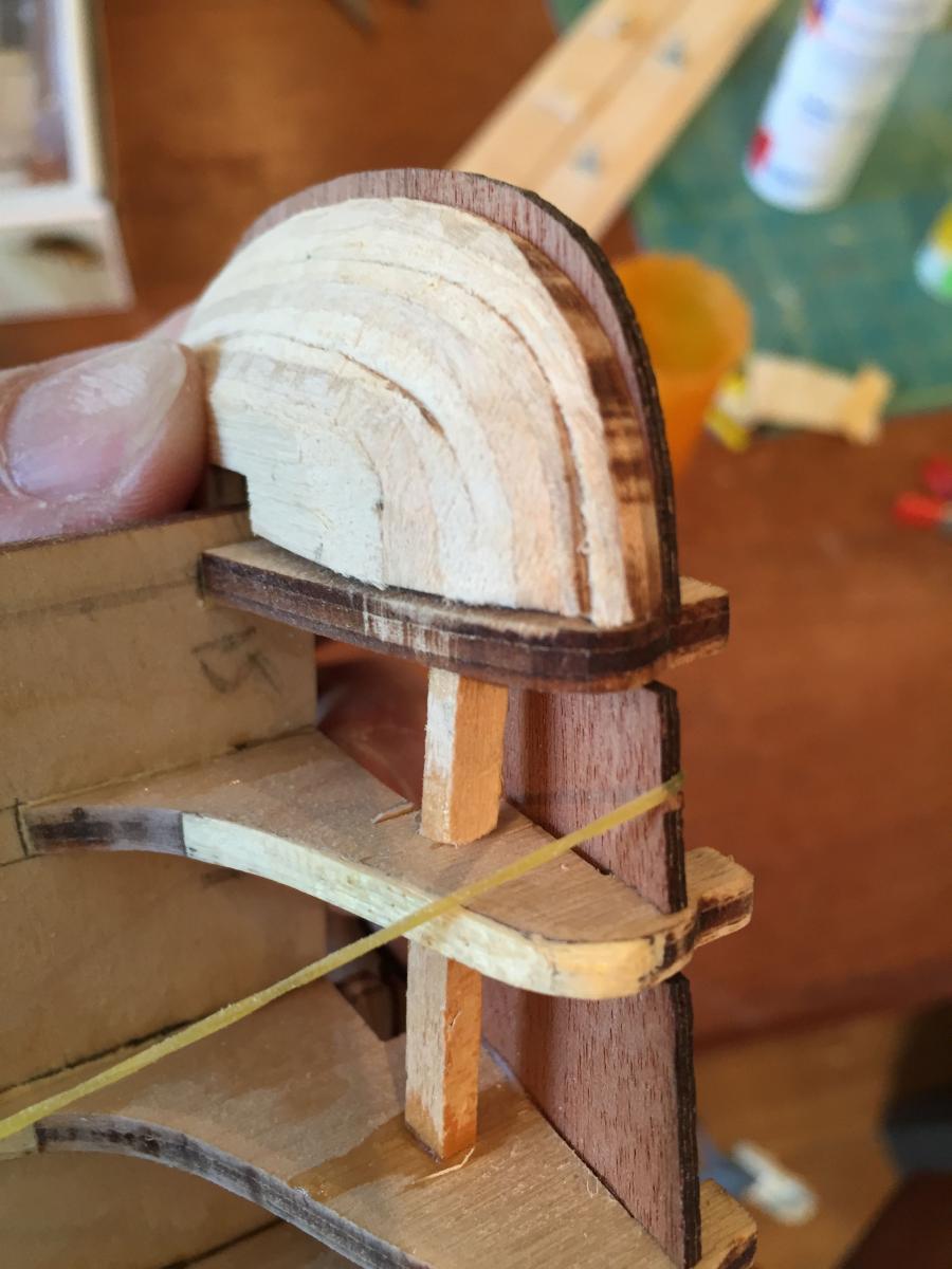
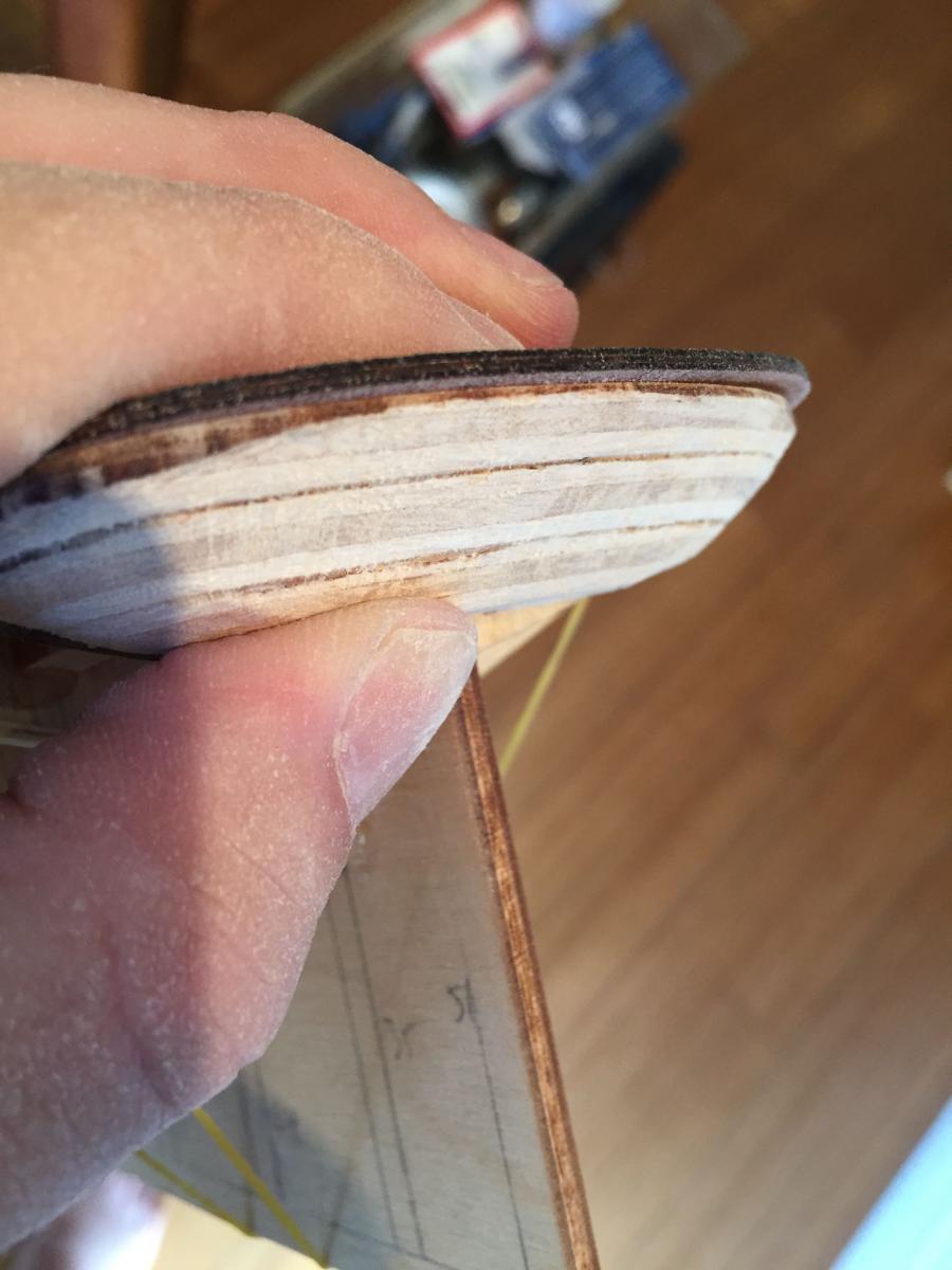
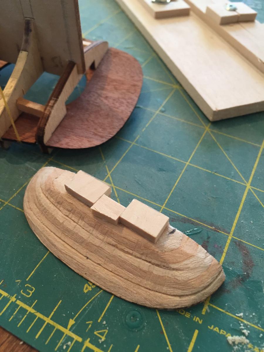
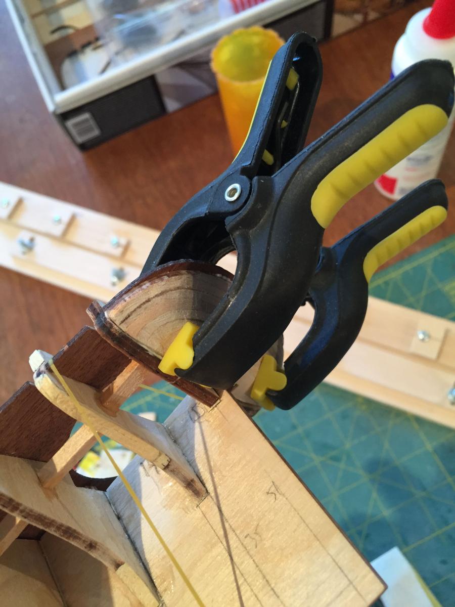
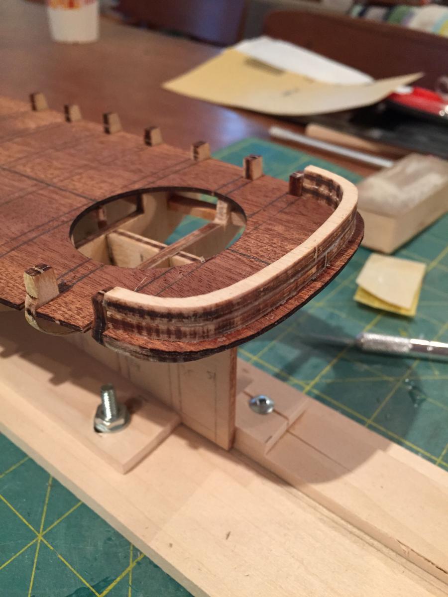
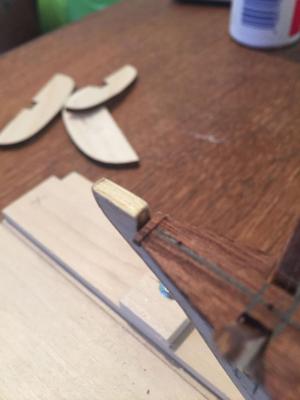
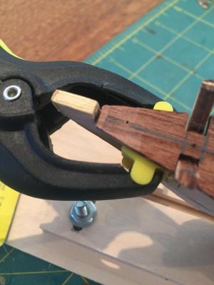
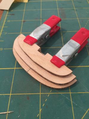
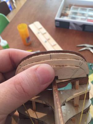
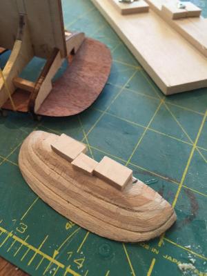
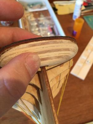
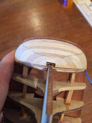
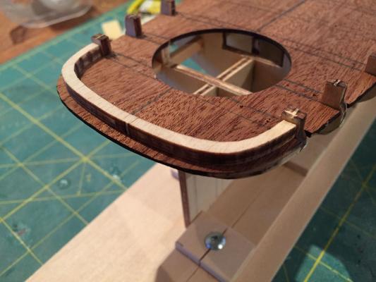
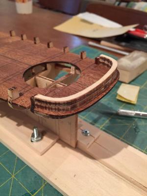
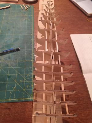
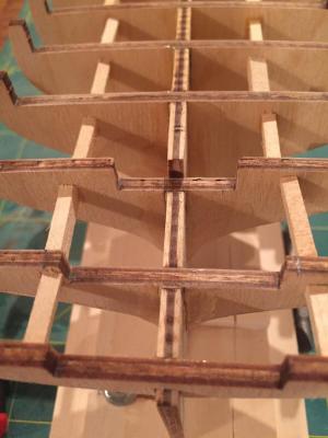
Well thew first major milestone has been reached - I've finished the framework - well, finished but for the fairing - and will proceed soon with the first planking. The last parts of the framework were 1. addition of some fillers at the bow 2. addition of a strip on the forward sub-deck to support the aft deck 3. adjustment of inside edges of bulkhead 14 to fit cockpit sub-deck 4. installation of aft deck 5. shaping and installation of stern filler blocks 6. installation of transom pieces atop aft deck 1. Bow fillers I think I mentioned earlier that the foredeck is a little short of the stem at the bow. Just for my own piece of mind and to provide a secure foundation for the margin/nibbing strake, I cut a small piece from the billet on which the sub-decks came, glued it and sanded it to shape - here it is A couple of bow fillers were also placed port and starboard on the false keel - these were shaped prior to installation, though they likely need a tiny bit more work which I'll take care of during the fairing.... 2. Quarter-deck step filler This is a walnut strip 1mm x 4mm, cut to fit between the bulkhead extensions atop the sub-deck at bulkhead 8. Very straightforward. 3. Adjustment of bulkhead 14 In the last post I noted that I forgot to notice that the inside depression on bulkhead 14 was cut too narrowly to accept the circular sub-deck for the cockpit. I only noticed this after the bulkheads were installed....I had marked the points on the bulkhead top where they would need to be cut to be flush with the cockpit opening on the aft sub-deck. Today, I used a combination of an x-acto saw and a scalpel blade to carve out notches and correct the bulkhead 4. Installation of aft deck Again - pretty straightforward - learning from my experience with the foredeck, I decided to drill the pilot holes through the bulkhead and keel tops - this made inserting the small brass nails much easier than it was with the fore deck, though I still had to use a small hammer, since I cannot find my tac hammer anywhere.....No photos of this, but see later ones of the completed framework. 5. Stern filler blocks This was a very involved process. The filler blocks come as 3 4mm thick blocks that must be glued together to form the basis of the stern filler. Two of these blocks have notches cut into them for the rudder/sternpost, while the largest and closest to the underside of the sub-deck has none. I drew a centre line on the topmost one (without the slot) and used that to line them all up - here they are glued and clamped. Once the glue was set, I held up the assembly in place and roughly marked the position of the flat transom area to distinguish it from the curved sides - this was just a rough estimate to get the shaping of the piece started I first used a sanding block to soften the edges and define the flat transom area more clearly. I then threw a sanding drum into my dremel and rough shaped the filler I noticed as I held the piece in place that it did not sufficiently cover bulkhead 15, so I added some small basswood blocks to it and reshaped it to fit - it is still not perfect, but bulkhead 15 will be faired into the fillers, so I'm not too worried. I used the dremel again to work it into a more refined shape, and then a sanding block to ensure the flatness of the transom area - it's really difficult to get a shot of the thing that clearly shows its shape, but..... I then glued and clamped the fillers onto the sub-deck and bulkhead 15 - there was, at this point, still some final shaping to do, but it needed to be on the hull for this to happen so I could ensure a good fit Finally I drew on the edge of the flat transom area on with a pencil - this pencil mark defines the rough location of the aft end of the hull planking and the area of the transom planking. It looks uneven in the photo, but it's not in reality, I swear 6. Installation of transom pieces on deck The kit includes 2 4mm thick pieces that are designed to serve as the transom above decks. I was worried that they wouldn't fit, but they fit perfectly - leaving the required 2mm lip on the outside which will become a prominent feature of the aft end of the hull once the planking is done. That's it, then - the first phase is done, and now it's on to the planking....we'll see how this goes. In the meantime, here's a photo of the finished framework...... Thanks for dropping by hamilton


- 165 replies
-
- 11
-

-
Yes, Bob - I'm pretending I'm retired!! And yes, Augie - I'm already appreciating it, though I've learned it needs a bit of finessing to stay true....been putting in some work on America today and made quite a bit of progress - almost finished the framework and starting to puzzle out the planking - always a weak spot of mine, but..... hamilton
-
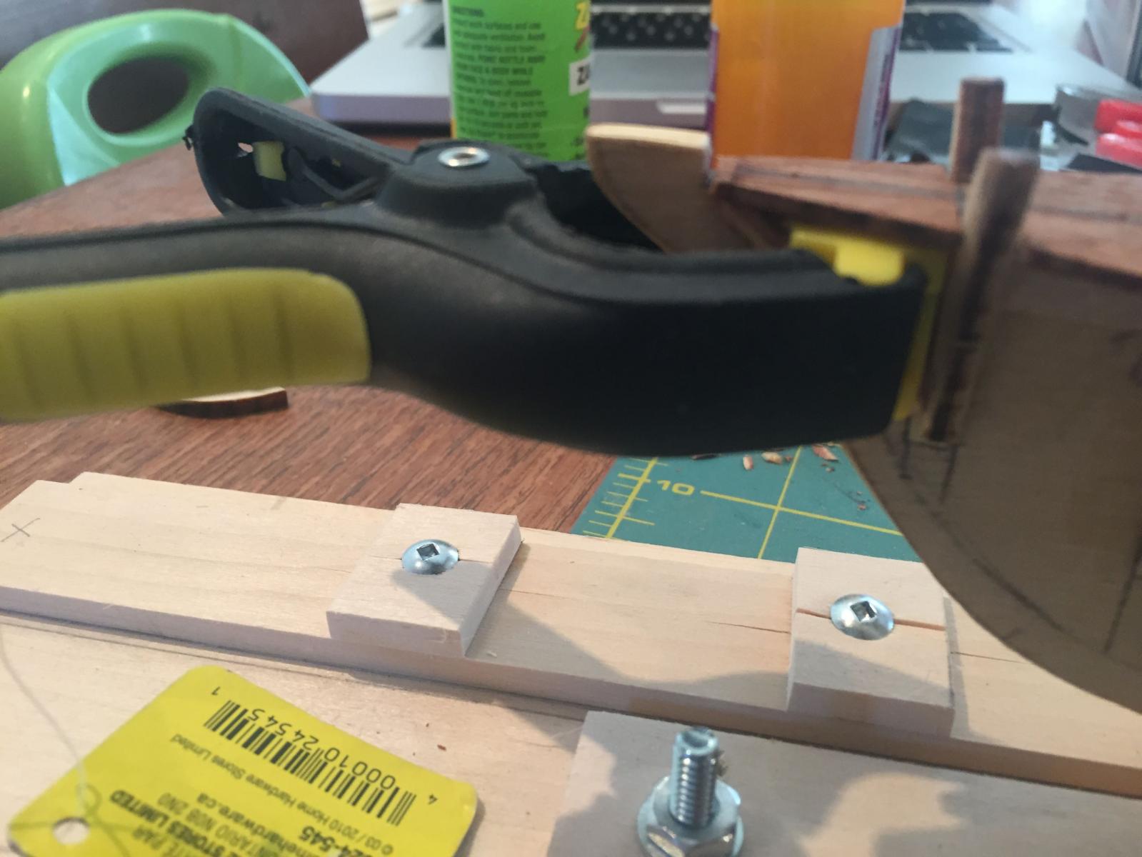
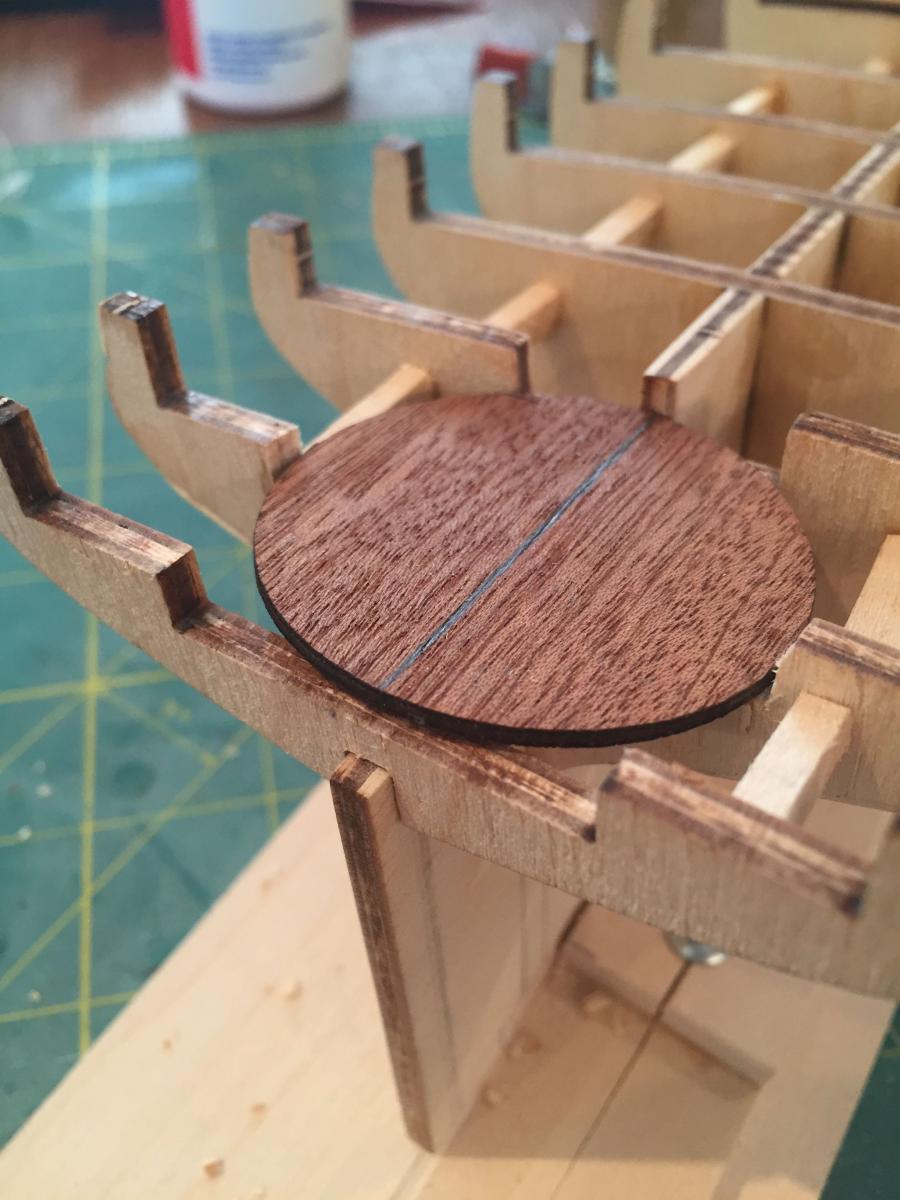
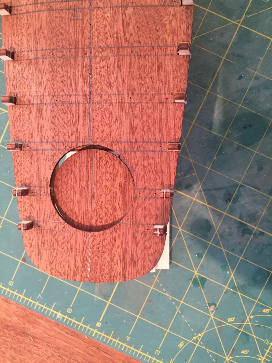
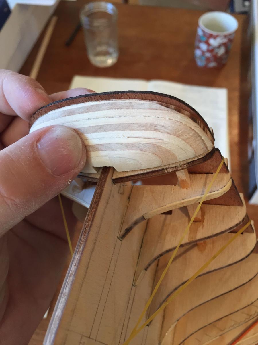
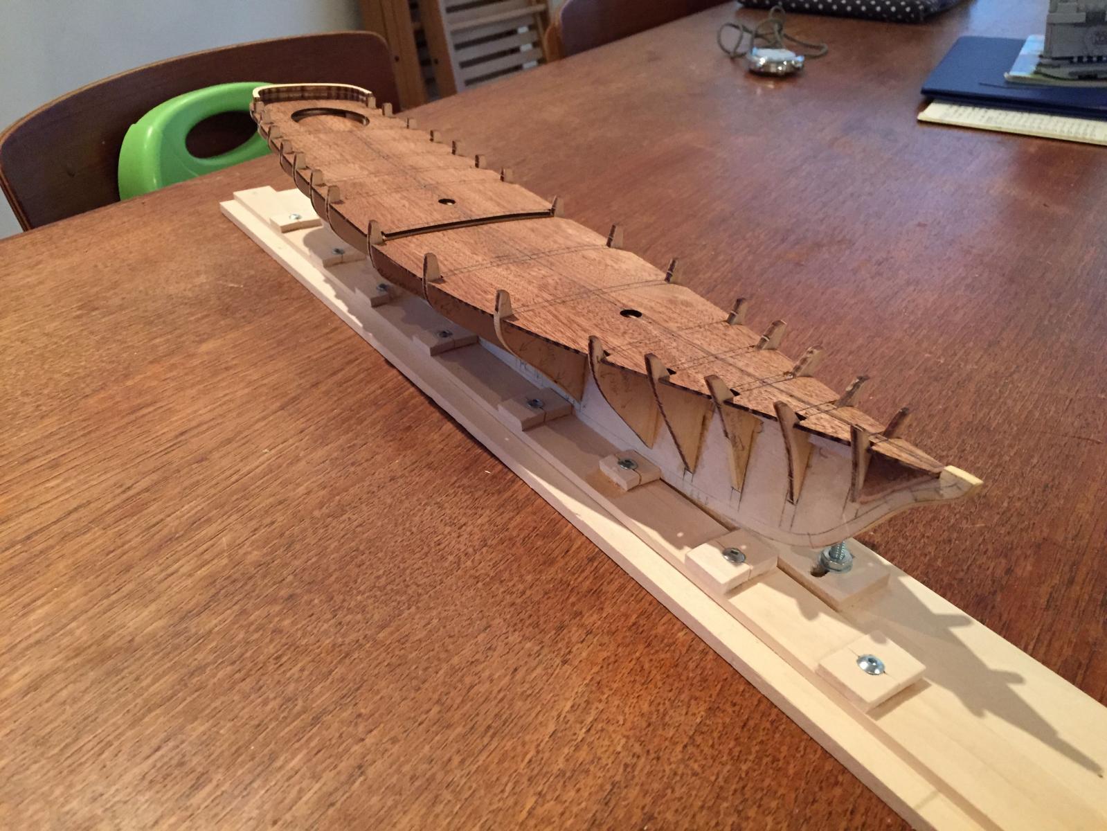
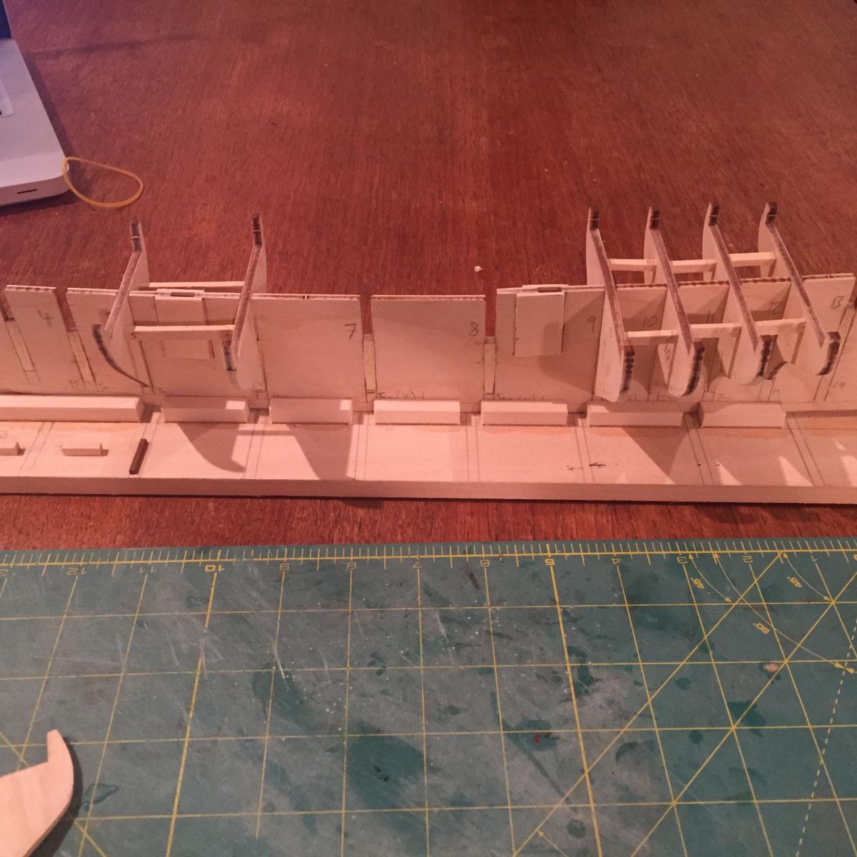
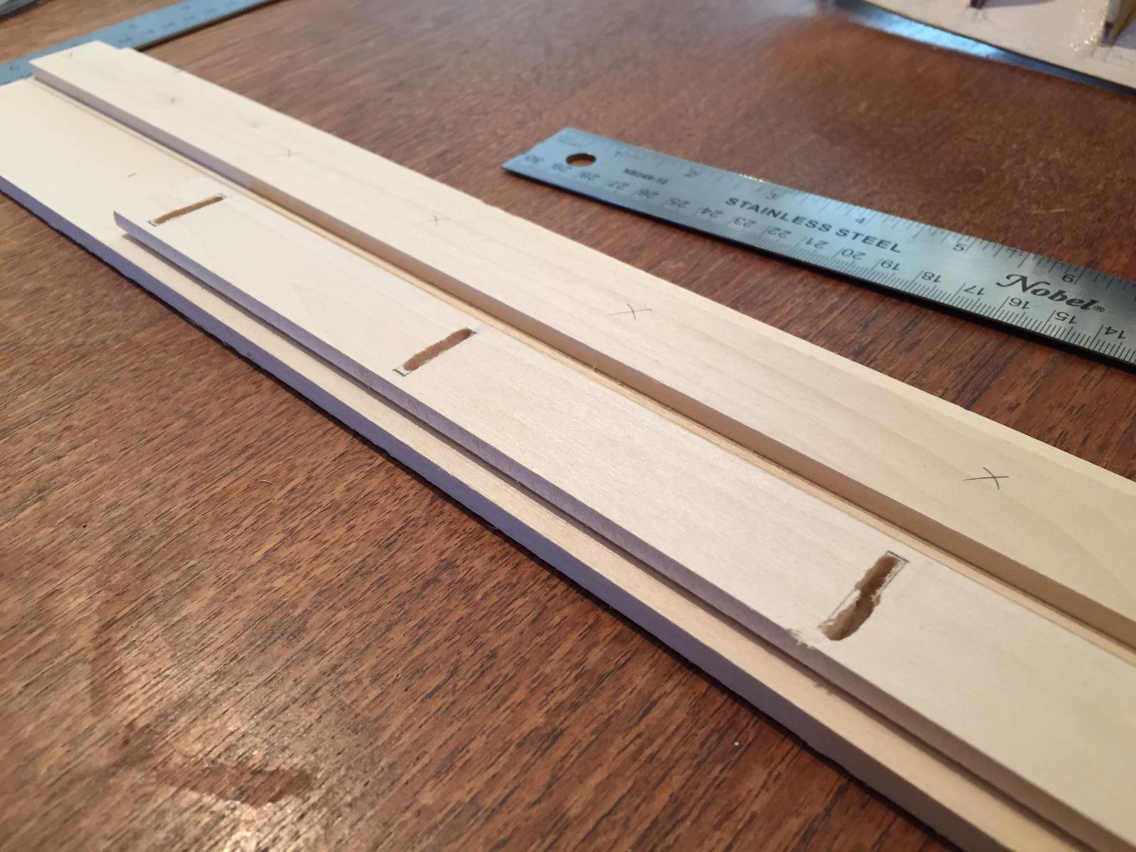
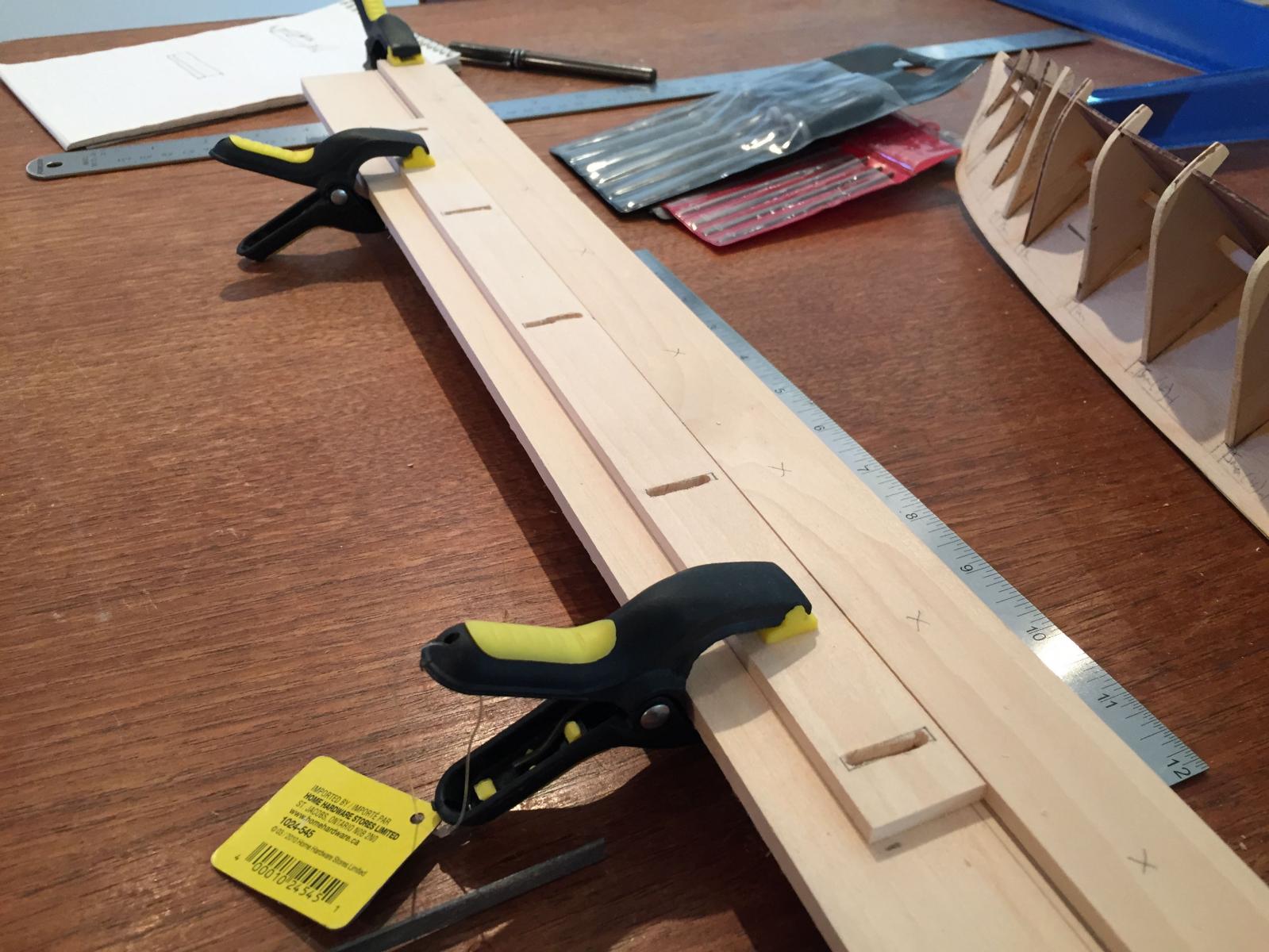
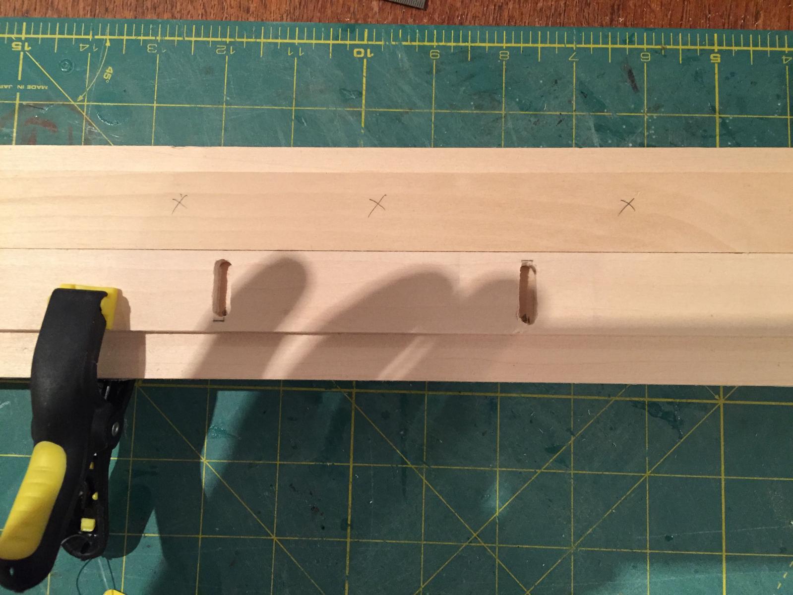
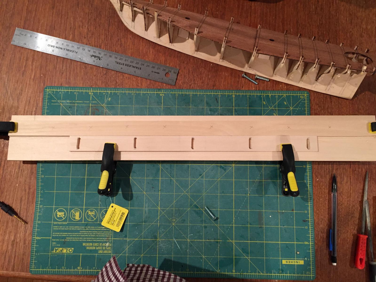
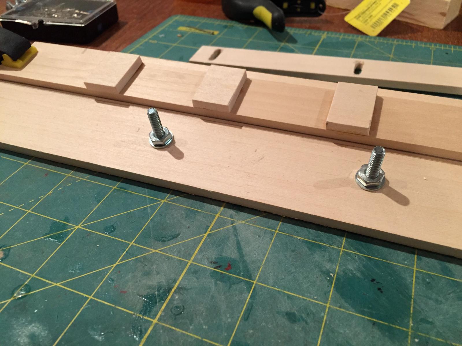
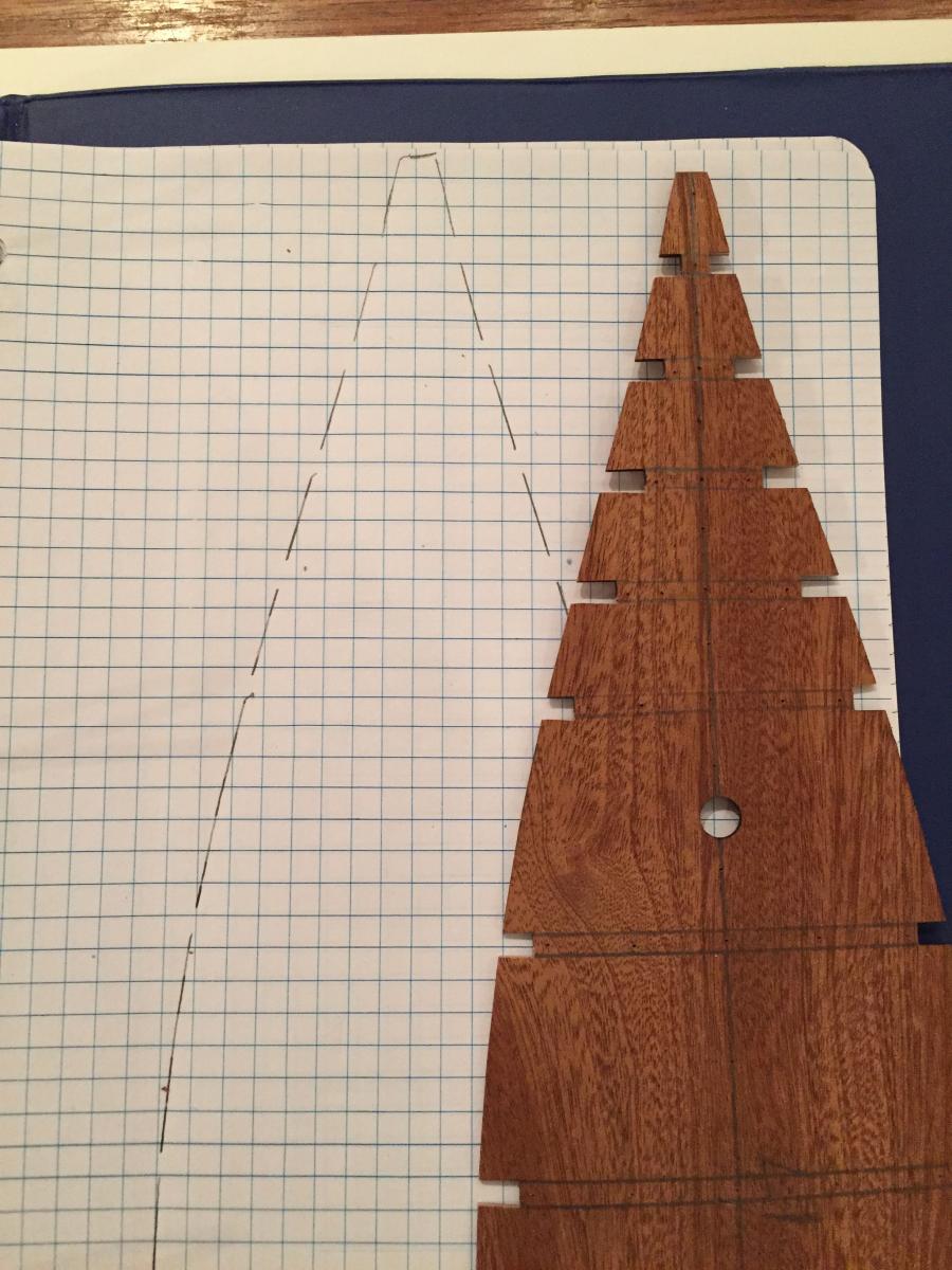
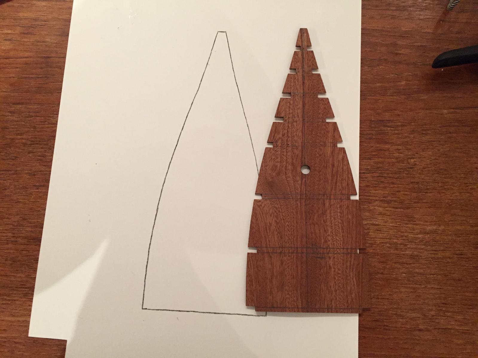
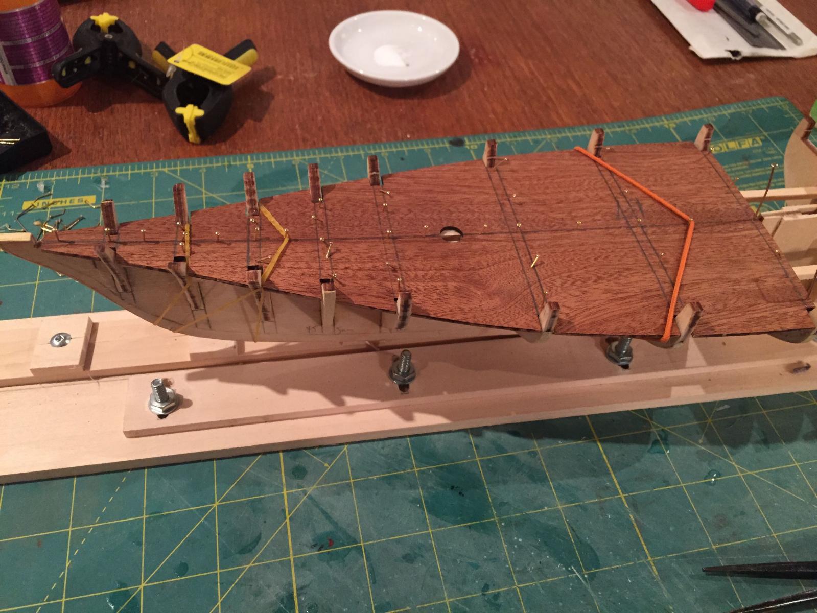
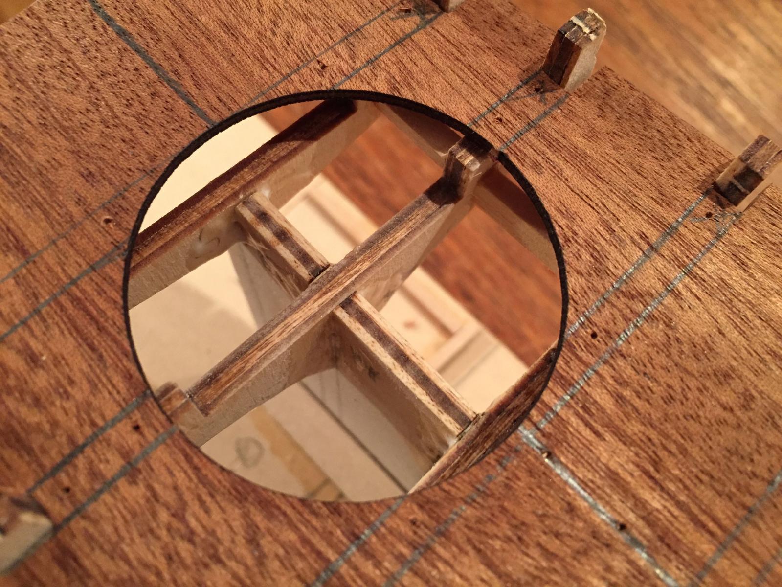
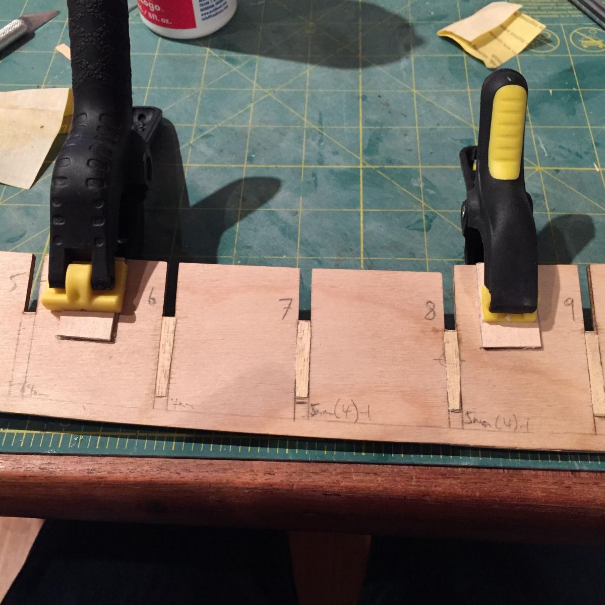
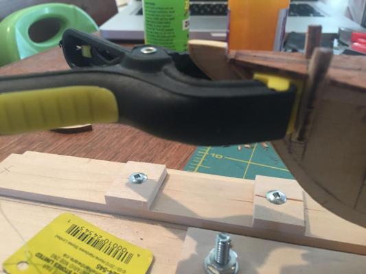
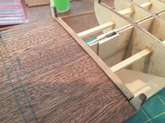
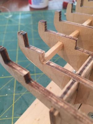
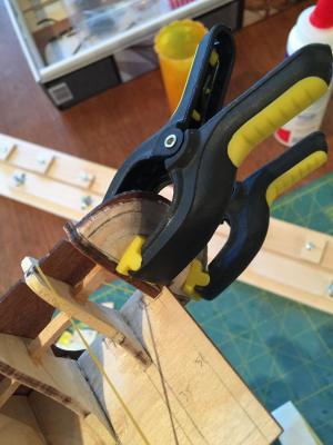
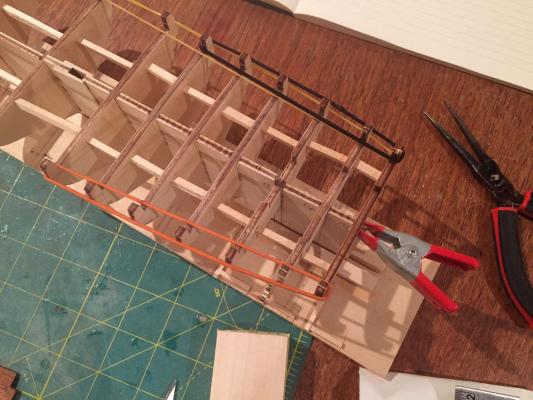
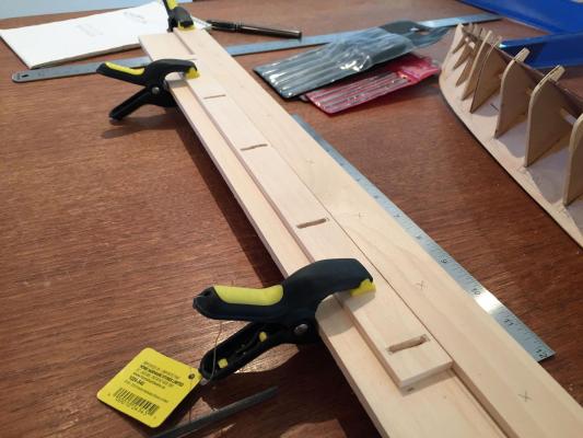
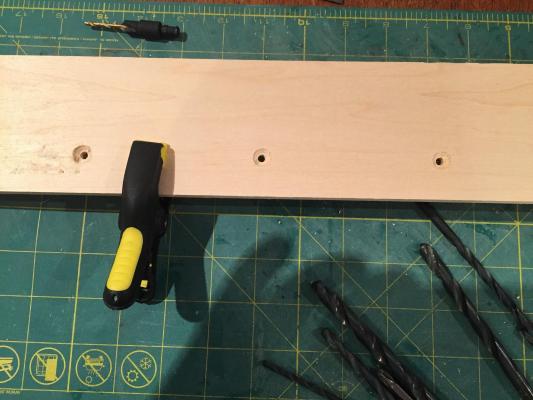
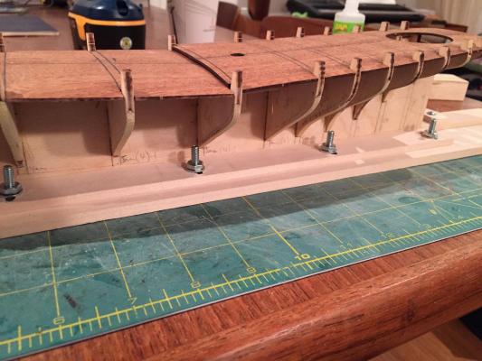
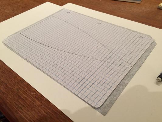
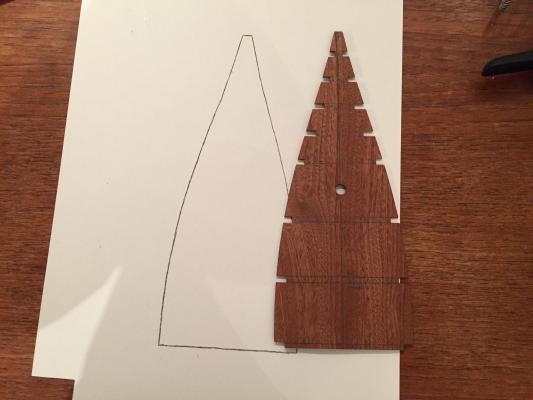
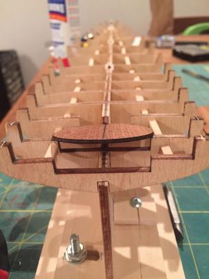
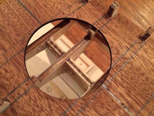
So my wife and sons have been away for a couple of days so I've been able to squeeze in a bit more modelling time since I don't have to wash dishes, make lunches, drive people around, sweep floors, change diapers, help with homework, read stories, and give baths but only have my paid job to worry about.... Since my last update, I've installed the bulkheads (with brace strips), made a building board with an adjustable clamp, and installed the forward deck. Here are some details. Part 1: Installing the bulkheads Before installing the bulkheads, I took measurements of the distance between them all and cut brace strips from some scare 1/8 x 1/8" basswood I had lying around. Cutting these was my first experience of using my new mini chop saw and i have to say that little thing is going to save some time and pain - at least it will when I figure out the finer points of using it....of the 28 strips I cut (14 for each side) only 8 actually fit.....I needed to remeasure and recut - fortunately I have a lot of scrap wood, so things eventually worked out....here are a couple of photos. Bulkhead 15, the aftmost one, has no support behind it so it was a little tricky to install. I placed a small clamp on the sternpost area of the false keel to keep it pushed forward and evened it out (and gave it a bit more forward support) with a couple of my wife's hairbands, which she will never miss. Part 2: Making a building board A little while ago I saw that someone on this forum (and I'm truly sorry I can't remember who) had made a building board with an adjustable keel clamp. I though this was a smart idea (and obvious once I'd seen that someone else had thought of it!), so I figured I'd make one for myself. I went and bought two 1" x 3/16" x 24" basswood strips and one 4" x 1/4" x 24" basswood sheet from a local hobby shop. I marked a centre line on the 4 x 1/4" board and then drew a reference line for the stationary part of the clamp 2.5mm out from the centre on one side. I used one of the 1 x 3/16 strips in its full length as the stationary part of the clamp, mounted on the 4 x 1/4 sheet. The mobile part of the clamp I cut down from 24 to 16" and then marked the positions of 5 evenly-spaced slots. I routed out the slots using a cutting tool in my dremel, mounted in the dremel workstation I bought a week or so ago. Here are the results with the very rough cut slots I then clamped the fixed 1 x 3/16" strip in position and clamped the movable 1 x 3/16 strip hard up against it and marked the far end of the slots on the 4 x 1/4 board, so I would know where to drill holes. The next three shots show this Once the positions of the holes were marked on the building board, I drilled them out from top to bottom with a regular 1/8" bitt. Once that was done, I drilled them up from bottom to top with a counter-sinking bit. Here's a shot of the bottom of the building board Once this was done, I realized that the slots I'd routed in the adjustable clamp were too narrow, so I widened them out with the dremel enough for the bolts to fit through them. I then gave it a test and the bolts fit fine and I could easily move the mobile clamp around and fasten it. I decided to use small screws to fasten the stationary clamp to the building board. I had thought of gluing it but for some reason didn't....Because of the length of screw I was using, I needed to mount small 3/16" thick pads on the stationary clamp at those points where I was going to attach it to the board. You can see them, plus the bolts for the mobile clamp, in this image Unfortunately when I put the screws in, these pads split as did the stationary clamp in some places. This was only minor splitting for the most part, but a couple of the pads split entirely in two. I had to double check the straightness of the stationary clamp to ensure that the splitting didn't create any warping and I also had to sand each of the pads flush with the edge of the stationary clamp using a sanding block. Here is a shot of the keel positioned on the building board Now I can hear you saying that those bolts are too long and they're going to hit up against the hull planking and the thing's not going to sit properly....yes - you're right! Which is why I'm going to go out tomorrow and buy some shorter bolts to replace these. In any case, I'm pretty happy with the results and now instead of building a new building board for every new model, I can just use this! Part 3: Installing the forward deck The final part of the build to round off this update is the installation of the forward deck, which to be honest was a real pain! I've not had issues with fixing decks to frameworks in the past....but I'm getting ahead of myself.... Before installing the deck I wanted to make a pattern of it, so I could properly plan the planking and potentially make a margin/nibbing strake and take patterns for waterways. I traced the deck onto a sheet of graph paper, then laid it on a sheet of bristol paper with carbon paper in between, black side down. I then simply traced the outline of the deck pattern and presto - there is was on the heavier bristol stock, which will act as a template for my decking... Once that was done, I could safely install the deck (I'll make another template in the same way for the aft deck when the time comes....Anyway, normally when I install the sundecks on models, I use stainless steel straight pins to keep the deck in place while the glue sets. In the past I've never had trouble pushing through the sub-deck and into the top edge of keel and bulkheads. But America was being very stubborn and I could not press the pins into it without bending them! At last I resorted to small brass nails, but when I went to look for my tac hammer, it was missing!! One of the boys likely grabbed it for some purpose and I'll find it under someone's bed or behind a bookshelf a few years from now....in the meantime, I ended up using a small hammer to pound in these tiny little nails....absurd!! I ended up bending quite a few of those, too. I don't know whether it's just these Mamoli bulkheads, but they are not easily penetrated!! In the end it got done, but to ensure a good fit, I threw a couple of elastics around the thing....here's a photo Part 4: A discovery After installing the forward deck, I put the aft deck back on dry to put the model away and thought I'd just quickly test the fit of the small circular cockpit sub-deck....when I did, I noticed that it did not actually fit down into the depressed area in the centre sections of bulkheads 13, 14 and 15, as it should....here's a shot to illustrate. It seemed that the bulkhead edges on the inside of bulkhead 14 stuck out too far instead of being flush with the aft sub deck, as they should be. Here's a shot to explain what I mean I laid the cockpit sub-deck in position and marked the inside edges of bulkhead where they cut across the sub-deck. I'll have to trim these edges back in order to properly construct the cockpit....you can kind of see my pencil marks in this photo.... but that's for another day....Anyway, thanks for dropping by and any and all comments, feedback and suggestions are, as always, welcome! hamilton


-
Looking really nice so far hamilton
-
Cutter Cheerful 1806 by rafine - FINISHED
hamilton replied to rafine's topic in - Build logs for subjects built 1801 - 1850
Beautiful planking job Bob - wish I could get results that clean. hamilton- 525 replies
-
- 2
-
-
- cheerful
- Syren Ship Model Company
- (and 1 more)
-
Great looking rigging Brian - maybe you mentioned it elsewhere here - but did you replace the kit supplied rope? Whatever you're using it looks really nice hamilton
- 831 replies
-
- 3
-
-
- Armed Virginia Sloop
- Model Shipways
- (and 1 more)
-
The stern and bulkhead planking look great! Looking forward to seeing your progress hamilton
-
Great work Jason - the planking is coming together very nicely hamilton
-
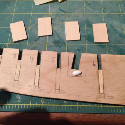
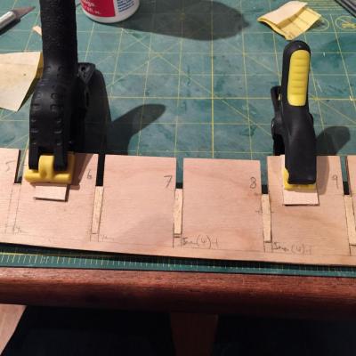
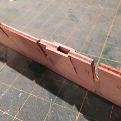
Hello there: Thanks all for the likes! I feel like I'm setting myself the challenge of making each entry here a little more dull than the last.....let's see how this goes.... I've finally completed shimming up the outside edges of the bulkheads - completed 9-15 this evening. 12 and 15 didn't need anything and the others needed varying degrees of adjustment, with bulkhead 14 being by far the furthest off from the plans. In any case, they're done! Not content to just do that, however, I decided to squeeze a bit more joy out of my evening by making and installing mast mortices. These were cut from some 1/16" basswood sheeting I had lying around from a previous build. And that, my friends, is it!!! No serious problems, no nagging questions, no great leaps of progress....just a bunch of shims and a couple of mortices.....sorry I can't be more interesting.....here are some photos, though.... hamilton
-
This is bringing me back! Built this one several years ago as my second ship build - a lot of fun as I recall, and Chuck's practicum helped a lot. Yours is looking great so far - have fun! hamilton
-
Like Brian said - I think either way looks good - a really nice looking model! hamilton
-
Looks good! My Phantom found its way into the trash after a child-involved accident, so it's nice to see others coming along. Gunther - coppering is not so bad - cheaper than a meditation class! hamilton
- 20 replies
-
- 3
-
-
- phantom
- model shipways
- (and 1 more)
-
Hi Jason: This is good to know - I have several CC kits on my wish list. The lack of patterns for the bulkheads etc. is not a deal breaker to be sure - especially since it is just as likely that the plans are off as the laser cut parts themselves. I guess with the CC kits you're forced (in a good way) to really attend to the model-as-built. I wonder if lifting lines from a place like an Anatomy of the Ship volume (where one is available as for Diana) would help as a reference - though I suppose once again it's the age old question of accuracy versus workable kit limitations..... hamilton
-
Hi Tom: Saw a fresh post, but no pics!!! That's ok....still recovering from the Hannah, though excited to see where you take her. I would never have considered smoking the interior of the bottle - an interesting idea and quite a puzzle.....I'm sure someone will have a suggestion - unfortunately, it's not me!! Looking forward to seeing your progress and hope you get a chance to get back to the table soon hamilton