
HOLIDAY DONATION DRIVE - SUPPORT MSW - DO YOUR PART TO KEEP THIS GREAT FORUM GOING! (Only 36 donations so far out of 49,000 members - C'mon guys!)
×


Dr PR
-
Posts
2,414 -
Joined
-
Last visited
Content Type
Profiles
Forums
Gallery
Events
Everything posted by Dr PR
-

Planking Question
Dr PR replied to Malazan's topic in Building, Framing, Planking and plating a ships hull and deck
I think a beginner should build first and read later! What do you want to do, read a book or build a model? If you are building a kit you don't need to read anything more than the kit instructions. Well, maybe. I have never seen a kit with really complete instructions, but you can get by. And you can always ask for help or advice here. There is great satisfaction from completing your first build. But if you get sidetracked trying to learn every detail of every part of ships, through all ages, and all nations, you will never get anything done. And beginners need that first build to learn if ship modeling is really what they want to do. If not they can still read the books if they are of interest. Maybe research is really what they will want to do, without wasting time building a model! The first build will not be a museum piece. It will be a learning experience. You learn about the materials - wood, plastic and metal. You learn about paints and glues. And you learn what tools you need and how to use them. And in the process you will have questions, and that leads to research. But one topic at a time, and as you need the information. -
Topsail schooner sail plans and rigging
Dr PR replied to Dr PR's topic in Masting, rigging and sails
Tewhano, Welcome aboard mate! Glad you found my posts useful. Have you seen my Okie Boat web site? https://www.okieboat.com- 104 replies
-
- 3
-

-
- schooner rigging
- Topsail schooner
- (and 1 more)
-
Planking Question
Dr PR replied to Malazan's topic in Building, Framing, Planking and plating a ships hull and deck
Richard is correct IF you are building "to scale" in all details. Many models are not built this way. Short pieces work best on a plank on frame model with dozens of closely spaced frames. The frames are relatively wide and closely spaced to give the planks the proper hull shape. You can also use actual ship building techniques for "stealers" and hooked planking. If you are building a plank on bulkhead model (most kits) with just a few widely spaced bulkheads short planks create two problems. One, the bulkheads are fairly thin on edge, giving little room for glue. This is especially true where you are trying to join two planks end-to-end on a bulkhead. Due to the curvature of the hull the plank ends will try to pop loose, especially on sharper curved sections of the hull. You can always attach additional wood on either side of the bulkhead to give a larger gluing area for the plank ends. Two, if a plank end attaches to a bulkhead on a curved part of the hull, the plank will try to run straight line to the next bulkhead and will not follow the true curvature of the hull. Where two planks butt together at a curved part of the hull they will not form a smoothly curved strake, but will have a sharp "kink" or "knuckle" at the bulkhead. This will not match the curvature of the adjacent planks. If you try to sand this junction to a smooth curve you may sand all the way through the planks at the join - this is not good! I have built several plank on bulkhead models using full length planks from bow to stern. It is tricky trying to get the proper width and curvature at the ends, but it isn't hard if you are careful while shaping the pieces. You will have to include stealers near the stern on most models. I think using short planks on plank on bulkhead models is just asking for trouble. Also, some kits do not have enough bulkheads, usually midships. This leads to flat areas on the hull between the bulkheads even if you use full length planks. If any two bulkheads are spaced more than 2 inches (5 centimeters) apart you should consider creating a new bulkhead midway between them. This isn't hard to do - just duplicate the widest of the two existing bulkheads, fasten it in place, and shape it to size with a sanding block. This will ensure the proper curvature for the hull surface. Jacek's suggestion of using two shorter planks instead of one long plank is a good idea, but be sure to place the butt joints near midships, and do not place the joins at the same bulkhead on adjacent strakes. Like he says, it is easier to just work on the bow and stern curvatures on separate planks than on one long plank. -
Tim, That traveler looks great! I have been debating whether to use a traveler on my Baltimore clipper. I have looked at dozens of plans and photos of schooners and it seems some use a traveler and some don't. That brings up the question of when and why a traveler is used? One school of thought is that the traveler allows the position of the sail to be adjusted to meet wind conditions. But some people say this is not correct. The other school says the traveler on the jib boom was used to haul the sail back to the bowsprit where it was easier to reef the sail. When the sail was being flown it was hauled out to the end of the jib boom. I am leaning toward using a traveler just because it adds detail to the model.
-
I posted a bit about anchor handling in small ships here: https://modelshipworld.com/topic/27410-small-ship-anchor-handling/?do=findComment&comment=787942 A line or chain called a shank painter was looped under the shaft at the flukes (crown of the anchor) to support the stowed anchor, and the ends were secured to timber heads or cleats on the rail or bulwark. A stopper rope to support the stock of the anchor was secured to the cathead on one end, looped through the anchor ring and then the free end was looped around a cleat or secured to a timber head. The anchor tackle could be loosened or removed and the stopper supported the head of the anchor. Apparently on some ships the anchor cable was removed from the anchor when at sea and stowed below decks.
- 89 replies
-
- 2
-

-
-
- Enterprise
- first build
- (and 2 more)
-
Making sheaves for blocks and bitt pins
Dr PR replied to Kevin Kenny's topic in Masting, rigging and sails
I do not have a lathe (on my wish list, but first I need a shop to put it in) so I have come up with a very simple way to make sheaves down to 0.078 inch (2 mm) diameter using ordinary brass washers. In this link I made sheaves for a 1:48 scale model: https://modelshipworld.com/topic/19611-albatros-by-dr-pr-mantua-scale-148-revenue-cutter-kitbash-about-1815/?do=findComment&comment=616985 For a list of brass washer sizes see this link: https://www.mcmaster.com/standard-washers/material~brass/ -
Tim, I'm not sure about using the bolt ropes to produce "skeleton" sails. I haven't seen a model rigged that way but it does seem a bit odd (unusual) to me. However, I have seen models where some of the sail rigging is included without the sails. For example the fore sails have halliards and inhauls/downhauls that can be hooked together when the sail isn't rigged (usually at the inhaul block on the bowsprit/stay). Likewise square sails have clew lines and sheets that can be hooked together at the end of the spar. Gaff sail outhauls and brails can be rigged this way at the end of the boom. Buntlines could be hooked to the spar. I'm not sure what you would do with bow lines that normally attach directly to the sails. I think you can include most of the sail rigging in this way.
-
I have been following this discussion because I went through a similar search a year or two back. Wolfram zu Mondfeld's Historic Ship Models (Sterling Publishing, New York, 1989) shows the construction of gun ports (page 96) and gun port lids (page 176) in pretty good detail. I realize many modelers play down Mondfeld's book because it isn't specific to any particular ship or nationality, and he doesn't list his references. This is true. But the book's greatest virtue is the descriptions of parts of ships as they evolved over the centuries and in different parts of the world. For example, he describes gun port lids for British, French and other Continental navies from before 1550 through 1890. Much of what this thread is about is discussed in his book. The book isn't perfect, but it does explain many of the differences you see in contemporary models from different nations and time periods.
-
Looks like you turned a sow's ear into a silk purse! Hope you can continue with the Dapper Tom. I love the topsail schooners.
-
Kieth, Your work, and the photos you post, are a modeler's eye candy! Beautiful research, design and implementation! One of these years I hope to achieve a similar level of perfection.
-
We had a board similar to the second one on the quarter deck (in port) of the USS Oklahoma City CLG-5 in the 1970s. It carried the names of all the officers assigned to the ship (about 200). Each name was engraved into a plastic strip. The name strips slid back and forth in metal guide rails. The "quarter deck" was the area where the officer's brow (gangway) attached to the ship - where officers left or boarded the ship. As officers came and went from the ship the name strips were moved left or right to signify whether the person was on board or ashore. This allowed the Officer of the Deck to keep track of which officers were aboard. I have no idea if the "officers name board" had an official name. Phil
-
William, Good to hear from you. I don't know where I will go with the project either. My intent was to create a complete set of 2D drawings that modelers could use. This turned out to be a massive undertaking - a side profile drawing takes 5-6 days to generate from the 3D model (on a 4.7GHz i7 machine with 32 Gbytes of the fastest RAM I could buy, running 24/7)! Then it will take a week or two to clean up the drawings and scale them for plotting. I wanted to build a 1:96 scale model, and the hull is partially completed. 3D printing has come a long way since I started the project in 2004, and I am considering converting many of the files to printing files. But there will be a pretty good learning curve and I don't know when I will start that. First I must build a workshop to house the tools and the model. Who knows when/if that will happen! Converting the 1 Gbyte of files to a new format for Flight Simulator is not something i am interested in doing.
- 54 replies
-
- 4
-
-

-
- 3d cad
- cleveland class
- (and 1 more)
-
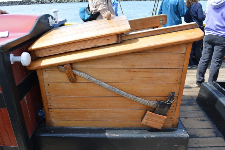
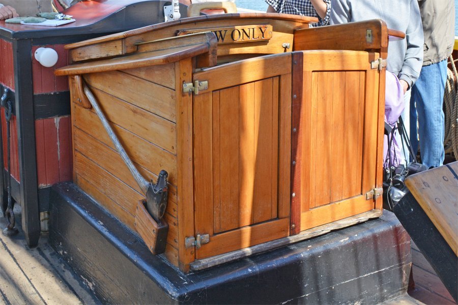
George, This is a little late, but I will post it for your information. Here are photos of a sliding hatch on the Lady Washington. This type hatchway was/is very common. The part under where the hatch slides back isn't wasted space - it is headroom as you descend the ladder. The top is not always sloping. On some vessels it is parallel to the deck.
-
Laggard, Patience and perseverance are the most important qualities of a wooden ship model builder, and if you have made it this far through this thread you have both! Don't be too critical of your first model or two. They are learning experiences. None of us builds a museum piece on our first try. There are a lot of new techniques and materials to learn about, and even some historical trivia to enlighten the experience.
-
One other consideration is the RF "noise" that electric motors generate. If you have machinery running in your shop you might not be able to get Bluetooth signals. Hard wiring is much more reliable.
-
Macro photos with an iPhone
Dr PR replied to Tomculb's topic in Photographing your work. How to do this.
Tom makes an important point! Phone cameras have fixed lenses that do not zoom. When you magnify the image on the screen you are not actually changing the focal length as in actual zoom lenses. Instead it takes single pixels and expands them to 4, 9, 16, ... pixels. This would produce a really "chunky" image with huge jaggies but the software blurs adjacent pixels to reduce the undesirable jaggies. But the result is a blurrier image with less sharp detail. Some cameras claim to have "macro" lenses, but they always have far fewer pixels than the regular or wide angle lenses. I am suspicious that all they are doing is just taking the small center part of the image of the wider angle lens for the "macro" photo and discarding the rest. So the actual 12 megapixel image is just cropped to 4-6 megapixels. Likewise, some cameras claim to have enormous number of pixels for wide angle photos, more than high level "professional" camera bodies costing $5000-$6000. I am skeptical about this - it may be marketing BS. They may be repeating a digital scanner scam where an image is actually scanned at X pixels resolution and then expanded in software to something like 4X pixels. An actual 12 megapixel image is blown up to 48 megapixels. Again, the results are blurrier than the actual optical resolution of the photo element. You can't get something for nothing! But at least one phone I know of has a sliding lens carrier that moves different focal length lenses in front of the same photo element. It has real wide angle, portrait and macro lenses. In this case every image has the same number of pixels. Having said all of this the only really important things is whether or not you are satisfied with the photo you get. If it is too blurry, zoom out and try again. I have seen some very nice close-up photos made with phones! -
Tim, Nice gadget. Not hard to guess the company you work for!
-
Tim, I have been studying schooner rigging for the last year or two, and have posted what I have learned here: https://modelshipworld.com/topic/25679-topsail-schooner-sail-plans-and-rigging/?do=findComment&comment=750865 The thread also includes discussions of the most common reference books for ship and schooner rigging. Although I am working on a topsail schooner model, it seems to me that the rigging is the same for the gaff sails on a fore-and-aft only schooner as on the topsail schooner. The only difference seems to be the addition of the square sails and their rigging to the normal fore-and-aft sail rig. I have posted a spreadsheet to calculate masting and rigging diameters for schooners. It includes the dimension calculations from some standard reference works for square riggers and schooners. The big difference between schooners and square riggers is the mast diameters. Because the schooner rig is much lighter the masts are thinner and different calculations are used for mast dimensions. Schooner masts carrying some square sails may be a bit larger diameter than the ordinary fore-and-af sail masts. Once you have the mast dimensions - the diameter at the partners (deck) the calculations for rope sizes are the same as for square riggers. One thing I have learned in my research is that there is no single "normal" or "standard" way to rig a schooner. If it can be done you can be sure it has been tried at some time. There is a tremendous range of variations in schooner sail configurations and rigging - at least a dozen ways to rig a gaff topsail! American built schooners often carried more extreme sail plans and rigging than the European counterparts, and pilot boats were no exception. There was serious competition between indiviual harbor pilots - they were paid by the job - and they raced out of port to meet incoming vessels. Pilot boats were built for speed.
-
Ladder steps
Dr PR replied to allanyed's topic in Discussion for a Ship's Deck Furniture, Guns, boats and other Fittings
In modern US ships the number of treads in a ladder (vertical or angled) depends upon the vertical length. This is divided to give a number of equal spaces between the treads (top of treads) somewhere around a foot (12 inches). This can vary between about 10" to 13" between treads, with the bottom tread on vertical ladders as much as 18" above the deck. Angled ladders tend to have the same spacing from the deck to the top of the lowest tread as the rest of the treads. Blueprints usually don't actually give the spacing, but just give the height of the bottom step from the deck and the distance from the top step to the deck above, and show some number of treads and say "Equal Spacing." The rest is left up to the shipyard. I suspect ladders have always been made this way. You have a space to fill with steps and you want them spaced in a reasonably familiar way. The fact that the spacing differs from ladder to ladder doesn't matter. Take my word for it - I climbed all over ships at sea with varying tread spacing and never had a problem missing steps. But it is important for the spacing to be equal on a given ladder. Also, the lowest tread should not be too close to the deck - that can cause tripping. And the top tread should be about the same spacing below the upper deck as the tread spacing in the ladder, but often is shorter if necessary to get appropriate spacing between the other treads. You don't have trouble finding the deck above the ladder when climbing - it is wherever your foot lands. - again, I speak from experience! Well, if you are climbing a ladder in the bow while the ship is pitching in high seas you may find yourself catapulted into the air just as you reach the top step with the ship dropping out from under you and then have momentary difficulty finding the deck, but gravity quickly remedies that! -
I have been looking for more information about the historical use of the jib stay traveller. Every book I have looked at mentions the traveller, but most stop there. Darcy Lever's 1808 "The Young Sea Officer's Sheet Anchor" is an excellent period source about rigging and sailing. In the ship handling part of the book in Section 84 "Taking in the Jib, &c." lever describes lowering the jib to the bowsprit to reduce wind effect on the bow that is making it difficult to keep the ship on course. "... when it is close down on the Boom, if the wind be likely to encrease, the Stay or Out-hauler ... is let go: it [the sail on the traveller] is hauled in close to the Bowsprit Cap and stowed away ..." So the traveller was used to bring the jib tack back to the bowsprit cap when the sail was to be stowed. However, there are also references implying that the traveller may not always have been positioned all the way forward, perhaps as Ian Grant said, to change the effect of the wind force on the sail. Lever discusses the effects of wind force on sails forward and aft of the center of gravity that cause the ship to change course into the wind (griping), and methods to reduce these forces to allow the ship to be steered without using the rudder (which increases drag when it is turned off midships). However, he does not mention reducing the fore sails for this purpose, but does describe raising and lowering them when turning the ship to allow the fore sails or mizzen sails to bring the ship about. In Section 60 "JIB, &c." Lever discusses the inner martingale stay that is attached to the traveller to generate a downward force to counter the lifting force of the jib stay. "Many vessels have only the outer Maringale-Stay; but the inner one is very serviceable when the Jib is a third, or half in, as it acts immediately under the Stay." [my emphasis] George Biddlecombe's 1925 "The Art of Rigging" (page 99) also describes hauling the traveller back to the bowsprit cap to raise the sail. "The Jib being ready to bend, haul the jib stay and traveller close in to the bowsprit cap; ... reeve the stay through the hanks (which are already seized to the head of the sail) ... haul it out to the traveller; hook the stay [to the traveller] ... then haul the traveller out to the jib-boom end (if required), and set the stay up." [my emphasis] So both authors imply that the traveller may be positioned at places other than full forward or full aft. But neither actually describes doing this to moderate the forces acting on the ship. So historically the traveller was used when setting or reefing the jib. But I still don't know how common the use of a traveller was, and especially on topsail schooners.
-
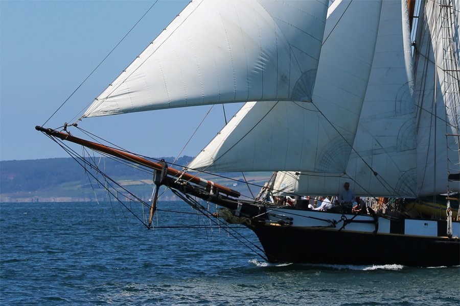
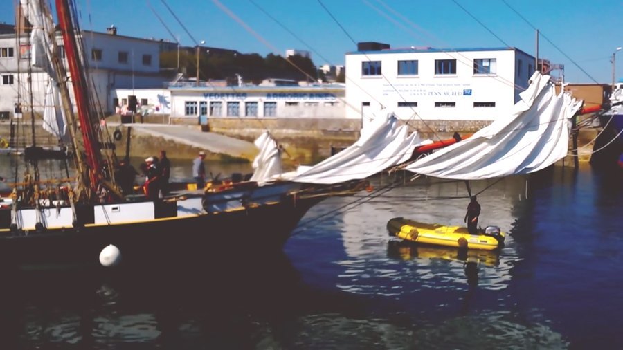
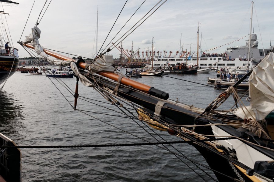
Thanks for the replies. Hauling the traveller back to the bowsprit cap to make it easier to handle the sail makes sense. But ... I have seen photos of vessels that have a traveller but do not use it when lowering the sails. Here are some photos of the modern La Recouvrance topsail schooner. First a clear shot of the outer jib and traveller. It appears that the outer jib stay also serves as the outhaul. The vessel also has a jib and a fore staysail. Here is a shot of the fore sails lowered: The dolphin striker (martingale) is visible, and the traveller clearly hasn't been hauled back to the bowsprit cap. Finally a photo of the furled sails. The traveller is still near the forward end of the jib boom. Why have a traveller if you don't use it? Many modern schooners do not have a traveller for the jib(s). So I was wondering how common it was in the past.
-
I am curious as to how common it was for vessels to have a traveller on the jib boom for the jib/jibstay? Lever, Biddlecombe and Lees describe how travellers were constructed and how sails were rigged to them. But many models do not show a traveller, and photos of modern vessels often do not show a traveller. The typical traveller was a ring that fit loosely around the jib boom (or perhaps the flying jib boom) and was free to slide fore and aft along the boom. The jib stay led to the traveller and the jib sail tack attached to the traveller. Inhauls and outhauls moved the traveller along the boom to position the foot of the sail. Note: This is a simplified description. The jib stay could also serve as the outhaul. Also, there were other types of travellers used elsewhere on ships. What was the traveller used for? Obviously it changed the position of the tack of the sail along the boom. But why? Searching this forum for "traveller" revealed opinions that it could be used to reposition the sail to gain best advantage of the wind. But some people say it was just a convenience feature to allow the jib to be hauled back to the bowsprit cap to make it easier to reef the sail without climbing out to the end of the jib boom. Since many vessels do not have a traveller, just how common were they? I am especially interested in topsail schooners, but apparently travellers were used on all types and sizes of vessels.
-
Kev, I see a problem with your sketch in post #6. If the fall of the boom sheet was secured to a cleat on the boom, and the boom was swung overboard, you wouldn't be able to reach the boom to untie the sheet. I think in a small rig like a long boat you probably would need only two single blocks , and the fall would be secured to a cleat on the rail or bulwark. It was common to secure the gaff sail sheet to a cleat on the boom near the boom jaws where it was always accessible. On larger rigs the sheet attached to a two block tackle that was attached to the jaws of the boom and the fall to a cleat on the boom.
-
I had another thought on this subject. The variable camber design was not limited to ancient vessels. The (relatively) modern barrelback runabouts of the early 1900s were designed with a drastically different camber from bow to stern.
-
Terry, Thanks for the drawings - you saved me the trouble! They illustrate the ideas perfectly. And they show quite clearly that with a constant camber deck the resulting "rail sheer line" where the deck and hull surfaces join is a smooth fair curve. There is a potential problem with the "saddle shaped" deck as shown in your drawing. Of course the curvatures are quite exaggerated, but even with milder curvatures there would be a problem laying constant width wooden deck planks on this surface. If they were placed side by side at the center of the surface (longitudinal and transverse center) they would splay apart at the ends. But this would be a problem only if the individual deck planks ran the full length of the deck. In practice the planks were much shorter, and each run would be created with multiple planks. This would make it easy to bend the planks to the curvature of the deck surface. I have walked the decks of several ships built this way and the plank curvatures are so small they aren't noticeable. In steel hulled vessels the deck plates were cut to fit the curvature.