

bolin
-
Posts
482 -
Joined
-
Last visited
Content Type
Profiles
Forums
Gallery
Events
Posts posted by bolin
-
-
Good idea using double sided tape.
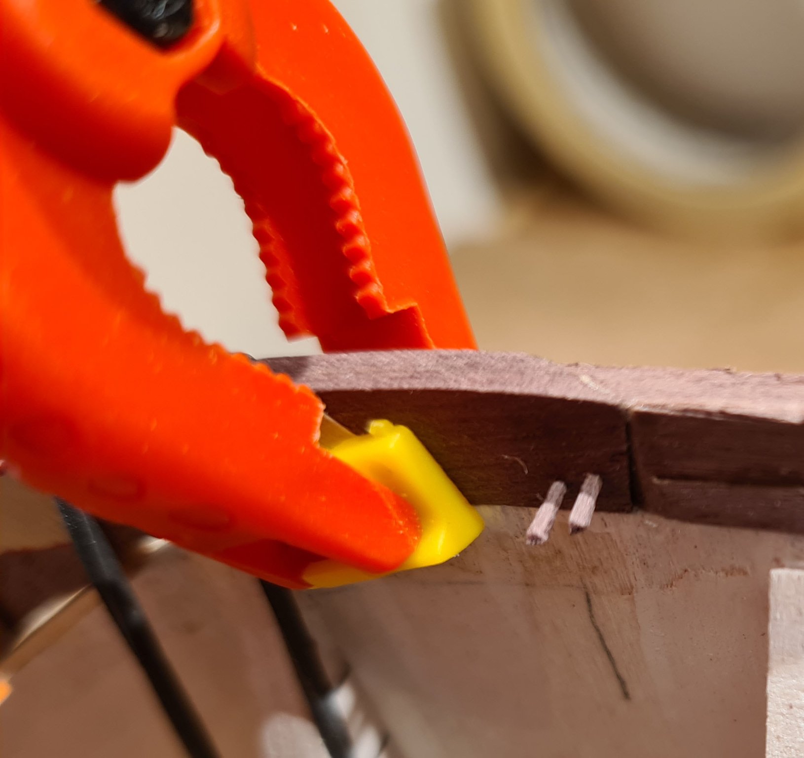
I have carving away on the stem and stern pieces and have now finished the rabbet for the planking.
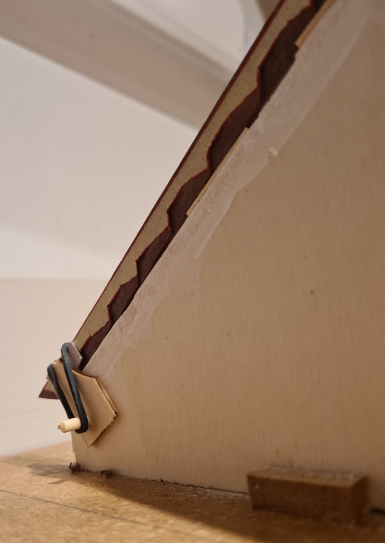
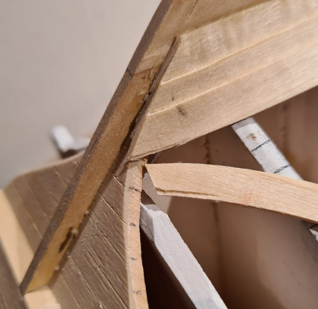
This means that the pieces are ready for joining with the keel. As can be seen in the picture below the fit is not as exact as I wanted. This means that the glue joint probably is a bit weak. To strengthen it I have added some tree nails.

So, now I'm finally ready to start planking. I have progressed slowly up to this point, so that I could continue with my other clinker model, the Sloop from Roslagen. I use that as a practice and to learn from my mistakes.
- Larry Cowden, Rudolf, ubjs and 7 others
-
 10
10
-
-
-
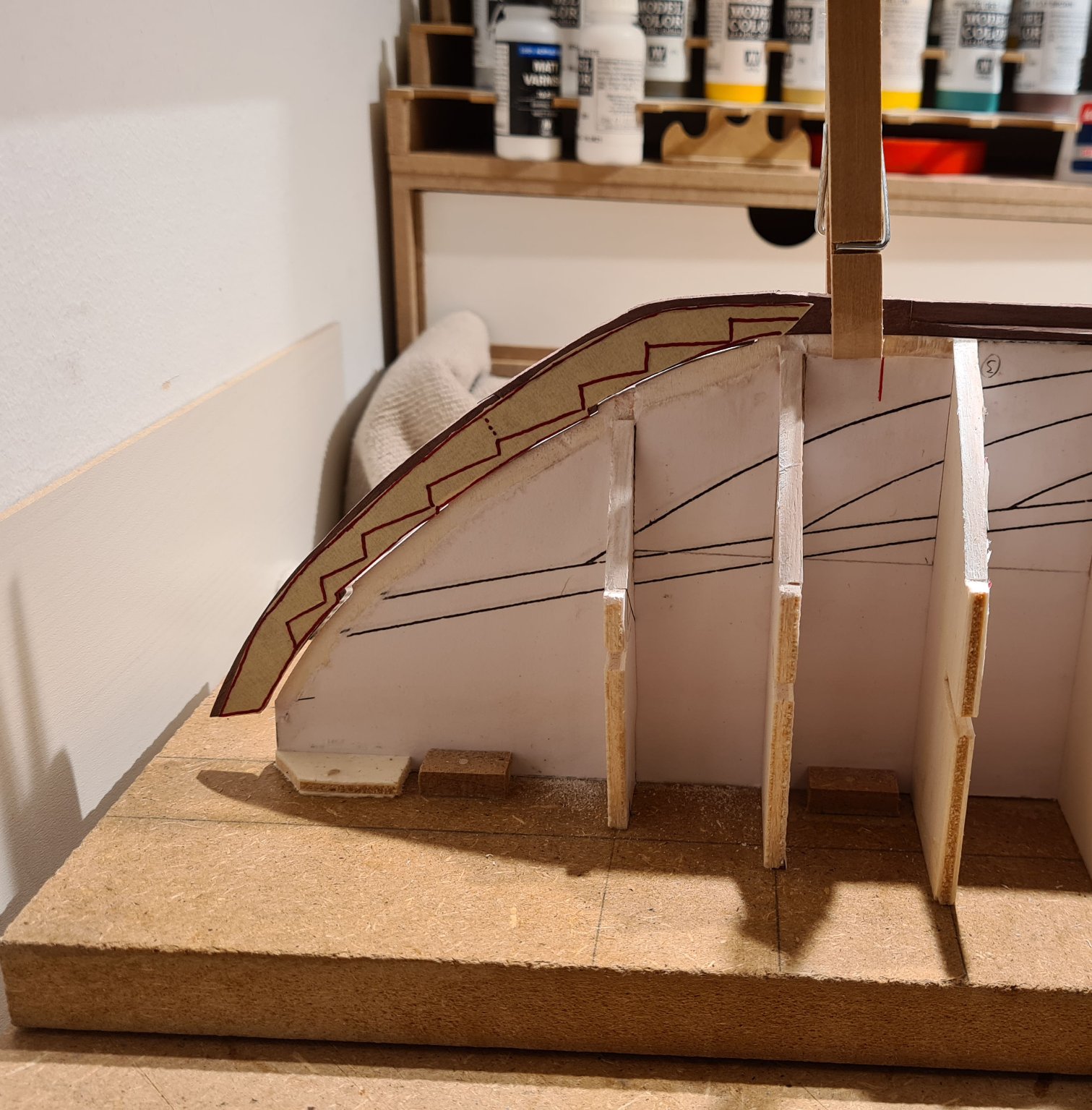
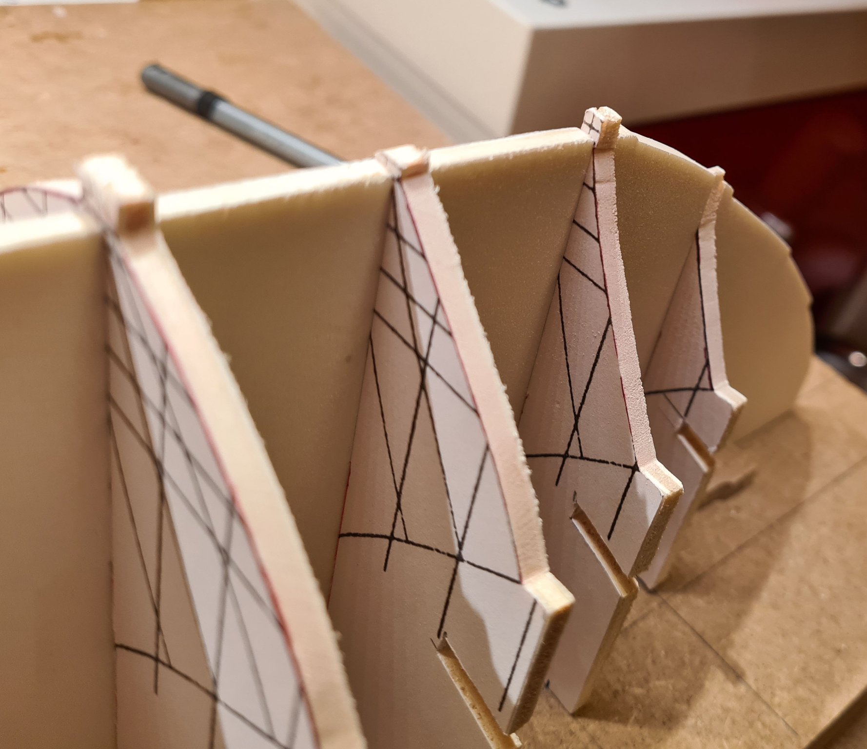
The rabbet line in the stem and stern should be "stepped".

This makes it a bit of a challenge to trace it to both sides symmetrically.
My solution is to put first put some tape to a sheet of plastic and trace the outline from the plan using bold lines. After that I put another piece of tape on the other side of the plastic and traced a mirrored copy.
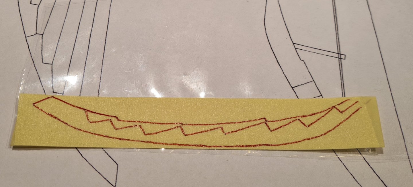

I then lifted the two pieces of tape and put taped them to the opposite sides of the stem and stern.
-
-
I would agree with Dan.
Some additional thoughts. If the model uses double planking you will have more chances to fill out any mistakes in the first planking. Since your model is from Billings I guess that there just a single layer of planks provided in the kit (that is what I seem to remember from build threads from other of their kits). In that case your concern is probably warranted. As Dan suggests the most problematic area is probably the bow. One alternative to extra frames would be filler blocks from a soft wood (e.g. balsa) between the most critical frames.
-
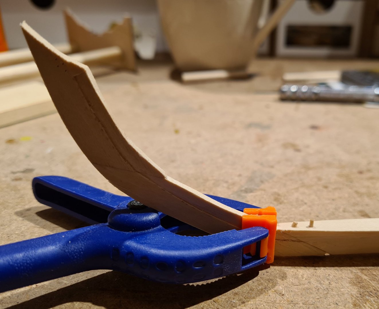
As I have no disc sander, or similar machine tool, I have made a jig for sanding down the scarf joints. Its basically a sled with constant angle where I hold the piece with my fingers.
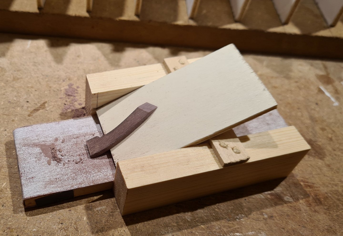
In the picture I show a piece that is the connection between the keel and the stern. Such a piece was found in the the archeological find, and in the report from the find it was called undirlutr. It is the Icelandic word for it. Its seem that such a piece has fallen out of use in traditional clinker built ships in the Nordic countries, so no word remains except in Icelandic.
The boat builder that built the reconstruction wanted to make the scarf joints longer, which would have made them stronger. But was ordered to build as the original, which I also will do. The scarf joint are about twice as long as they are wide.
Next, the joints can be glued together, below I show the stem. I glue the two pieces making up the the stern and stem together first, so that I can cut a rabbet while they are still laying on a flat surface.

I have also started to bevel the keel to meet the garboard at the correct angle.
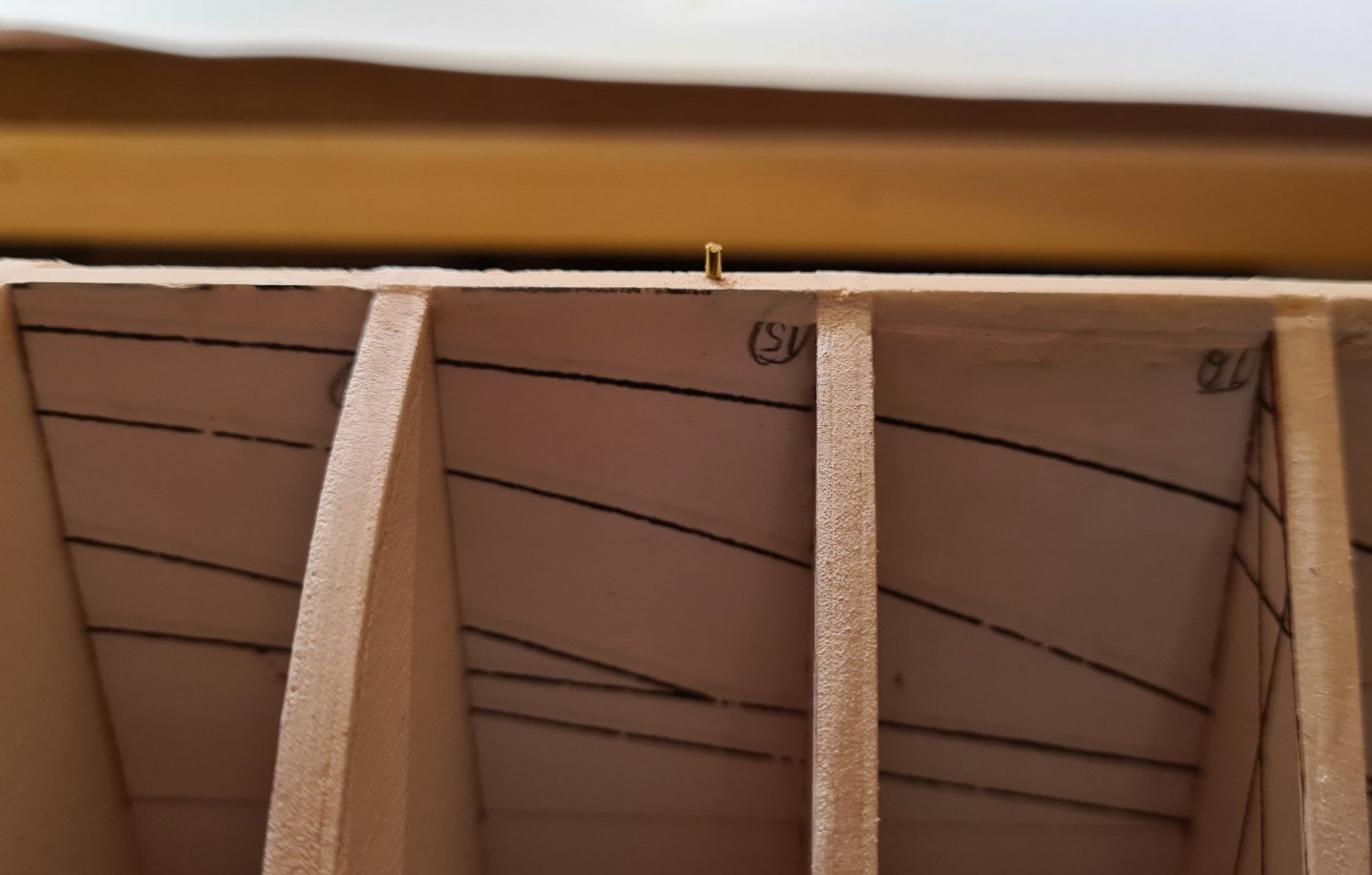
With experience from my "practice build" Sloop from Roslagen I have devised a way to keep the keel fixed in place. I have added two brass pins in the building form, and corresponding holes in the keel. The pins are placed where the frames will sit, so the holes in the keel will be covered later.
Cheers
- Brinkman, Larry Cowden, thibaultron and 5 others
-
8
-
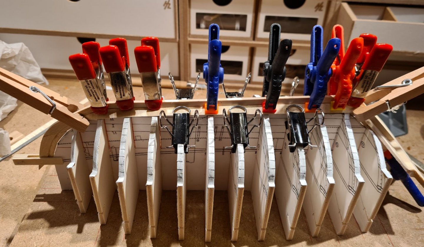
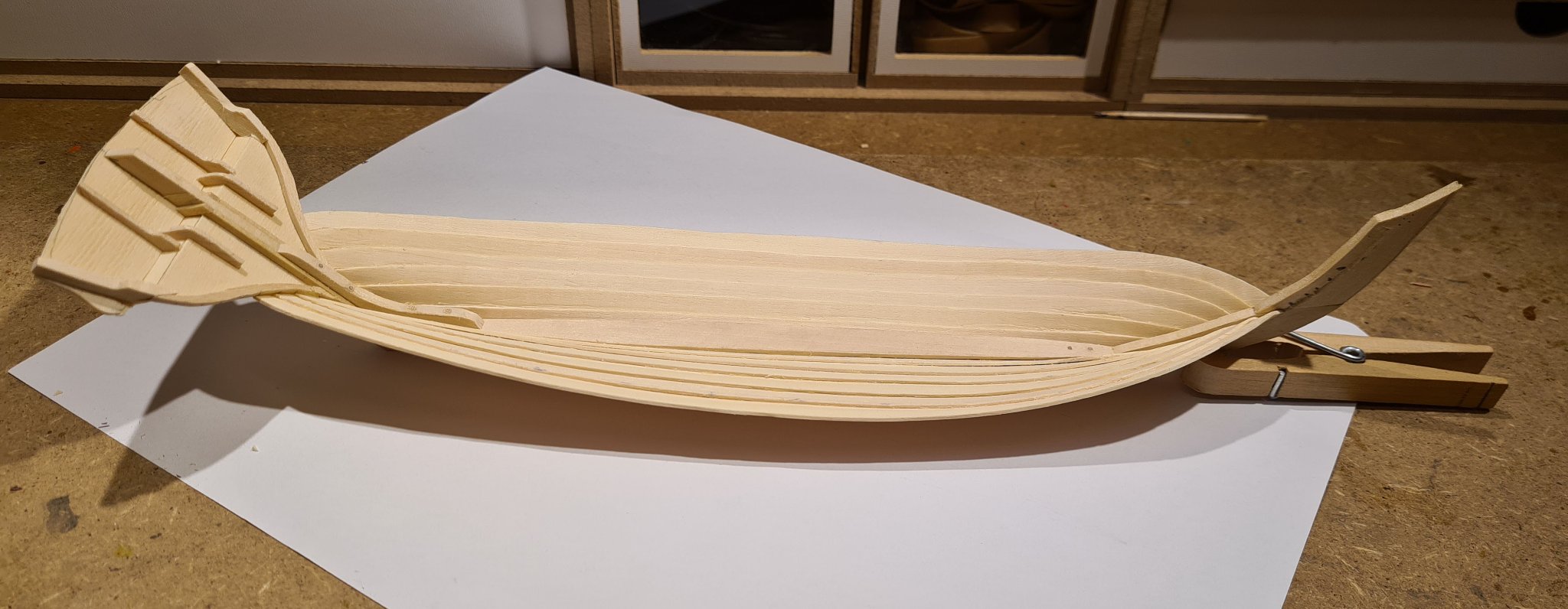
It feels like I'm starting to get the hang of how to do the clinker planking. Just seven more strakes to do.
Today I will just share a picture of the cutout at the end of the planks that reduces the overlap at the rabet in the stem and at the transom. These are a bit tricky to cut out, but I have thus far avoided to cut through the planks.
-
-
-
Thanks for all your input on rivets Schrader. I have actually been searching for some tips, and your is by far the most detailed I have seen. Very valuable. Thanks.
I would like to use metal if i can find a reasonable process. There will be about 2000 rivets, so I need to find an efficient method.
- mtaylor, Schrader, Larry Cowden and 1 other
-
4
-
On 10/30/2020 at 1:10 PM, Louie da fly said:
Walnut has a reputation of being easily broken and unwilling to bend without splintering. However, I'm using it on my Great Harry without much trouble, though my planks are pretty thin because the model is at 1:200 scale. What is the thickness of the planks on the Helga Holm?
The planking is about 22-25 mm in full scale, so just little less than 1 mm in my model scale. Since the ship is so long and narrow there will net be to much of bending, but a bit of twisting of the planks. It hope that it will be manageable, we will see.
- thibaultron, Larry Cowden and mtaylor
-
3
-
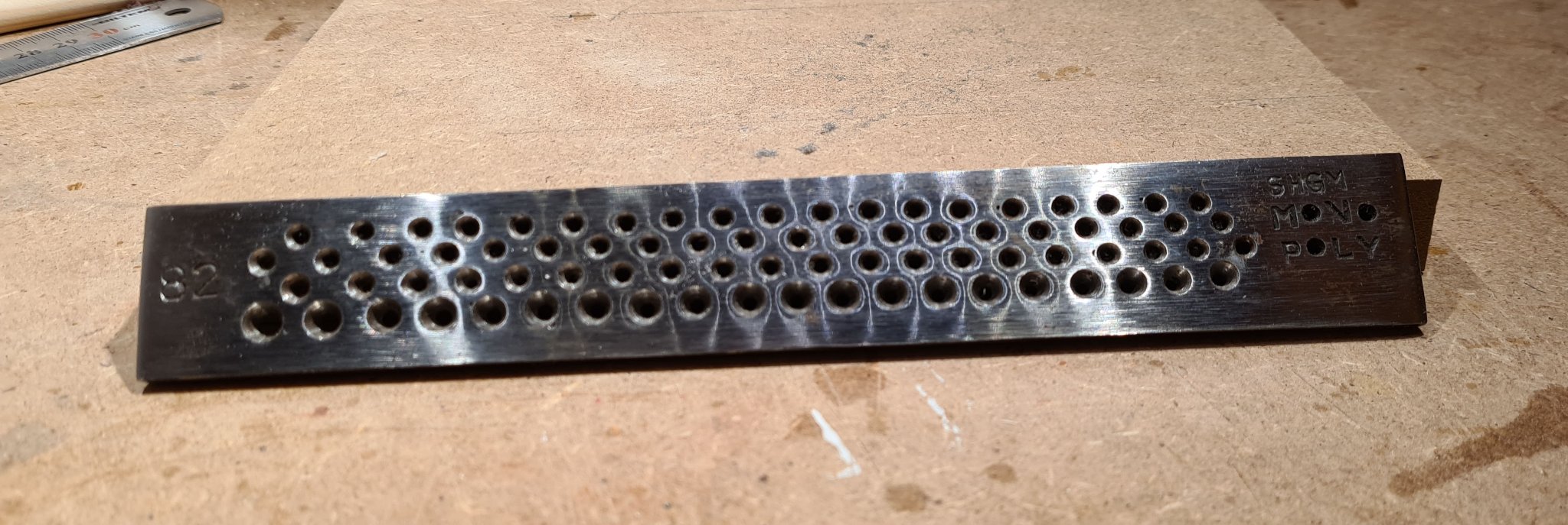
Maury, thanks for your input. I suspected that it might be the case when I bought the draw plate. I have also confirmed that it is not really built to be used for wood. It works reasonably well when I draw the wood backwards, then it shaves the wood thinner rather than pressing it together. However, if I will need any larger numbers of tree nails in the future I need to get a better tool.
On my model I have now finished the second strake.

-
The first plank (the starboard garboard plank), cut, shaped and glued.
- KeithAug, liteflight, mtaylor and 3 others
-
6
-
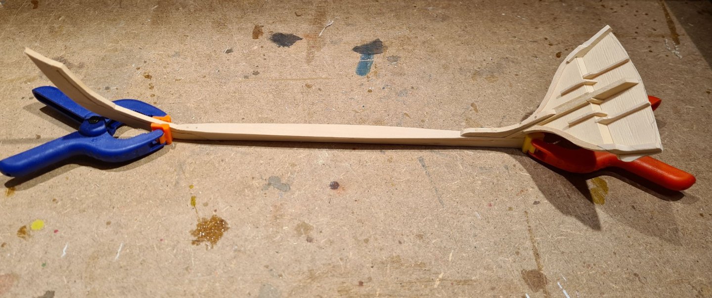
The keel and the pieces for the stem and stern has been cut out and fitted on the inside (upside) to the build form. Unfortunately I think I need to redo the keel, the strip that I glued on top did not get fully centered.
Thus far I'm rather happy with walnut. Its easy enough to cut and sand, but gives much cleaner edges and more even surfaces than the lime and basswood which I have used before.
The next step is to figure out how bevel the edges for scarf joints. It would probably be easier with a disc sander, but I don´t have one. I will need to figure out some jig that gives exactly the same angle on all pieces. In the picture they are just overlapping and held together with the clamps.
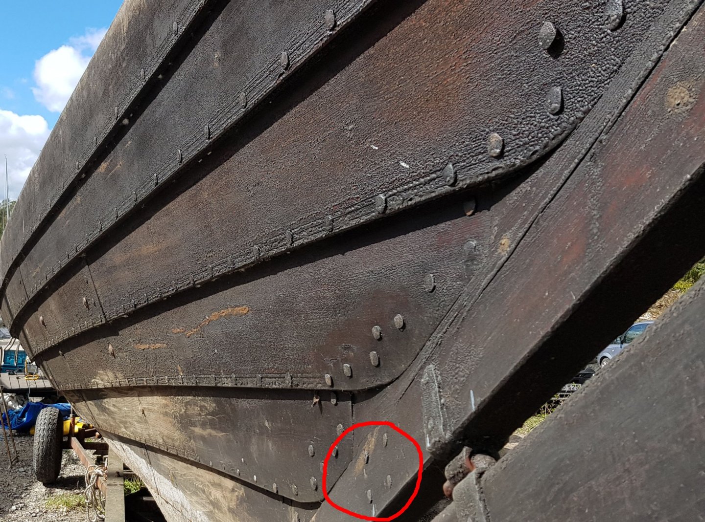
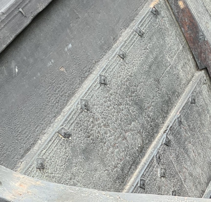
The joins between the pieces in the keel, stem and stern where riveted in the original find. See the picture below of how it looks on the replica.
I have been thinking for some time on how to model the rivets. My current best idea looks like this:
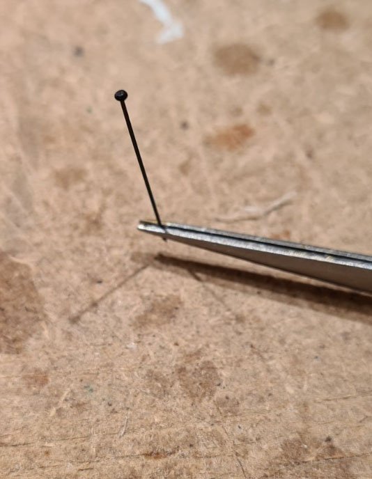
Its made from bristles from a plastic brush which I have melted in a flame. The head was flattened before it cooled. The next step is to find a good way to model the other side of the rivet. Maybe black paper or card?
Cheers
- Schrader, mtaylor, thibaultron and 4 others
-
7
-
You are most welcome wefalck!
Today I reinforced the knee at the transom.
Then I proceeded with shaping the outer line of the stem, which I had left oversized when I first cut them out. I also beveled the corners of the transom where the planks will land.
With that done I finally feel ready to start the actual build, that is to start the planking. Up till now it has more felt like preparations.
By tradition there shall be 11 strakes up to the wale. I suspect that it will take some time to complete.
-
-
With the build form finished I can start to assemble the keel with the stem and stern.
The fist try to glue the stem did not work, the glued join was to weak and broke off when I started handle it. I decided to use tree nails to reinforce the join. To create those I bought a draw plate. Its the type for drawing metal wire, but it seem to work just fine with grill sticks as well.

So with my first tree nails I reinforced the stem.
And proceeded to glue the transom piece to the keel as well. Not that the keel will be shortened to correct length now that I know exactly what it is.

- liteflight, grsjax, Mike Y and 4 others
-
7
-
With all your preparations I can understand the celebratory feeling when the first steps are taken. Well done! The instructions looks clear. I wish you luck.
-
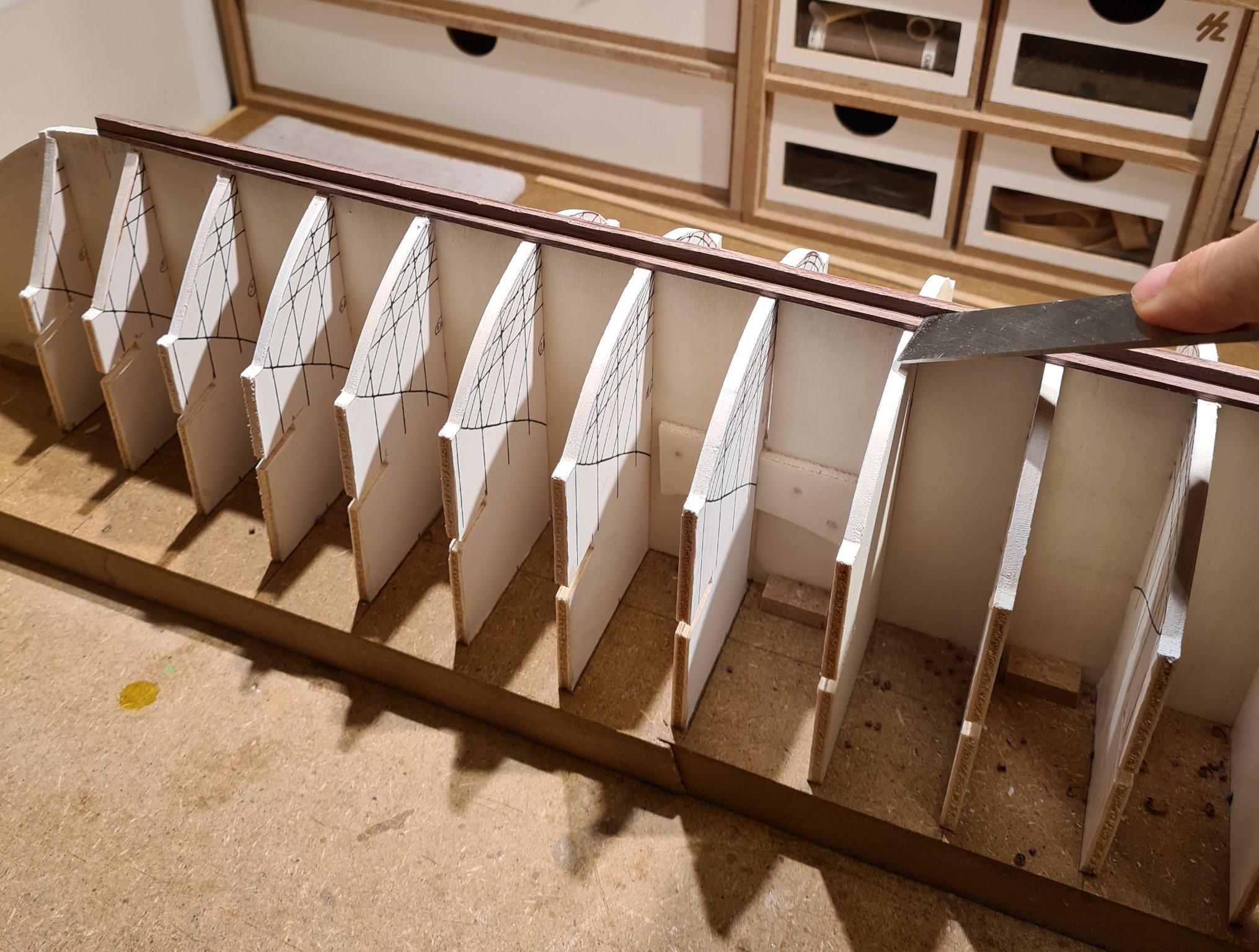
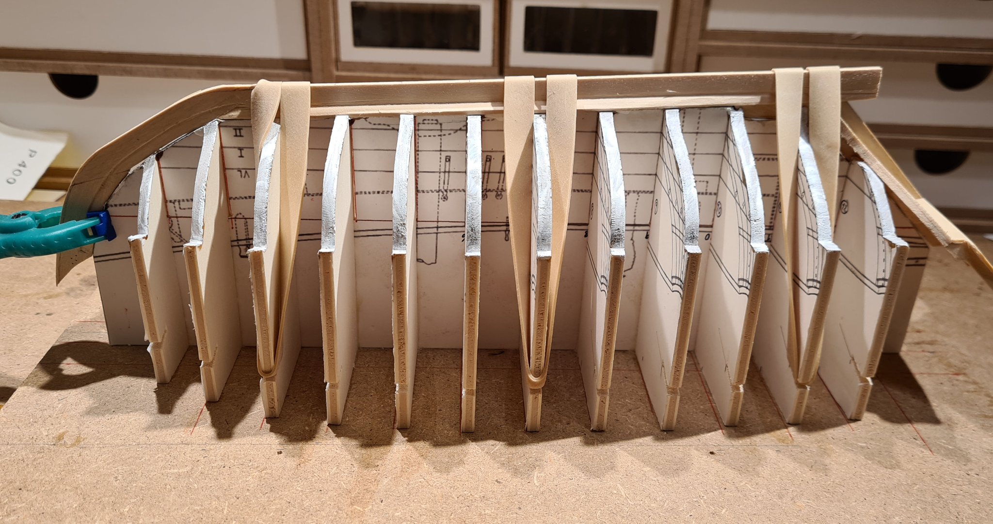
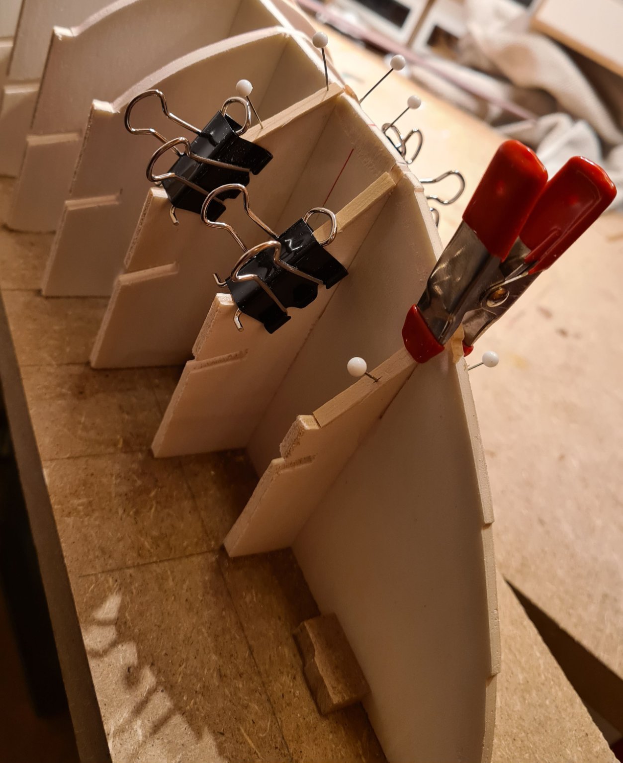
After beveling the frames and checking again with a strip of wood I decided that I need to widen the first three frames and last two. I will start with 1 mm strips of wood on each frame. That should be enough in the aft, but may not be enough in the bow.

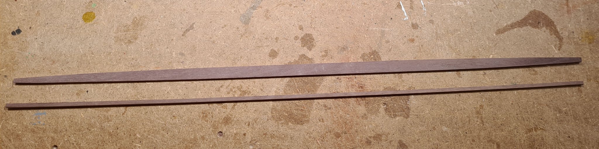
I have also started creating sawdust for the actual ship.
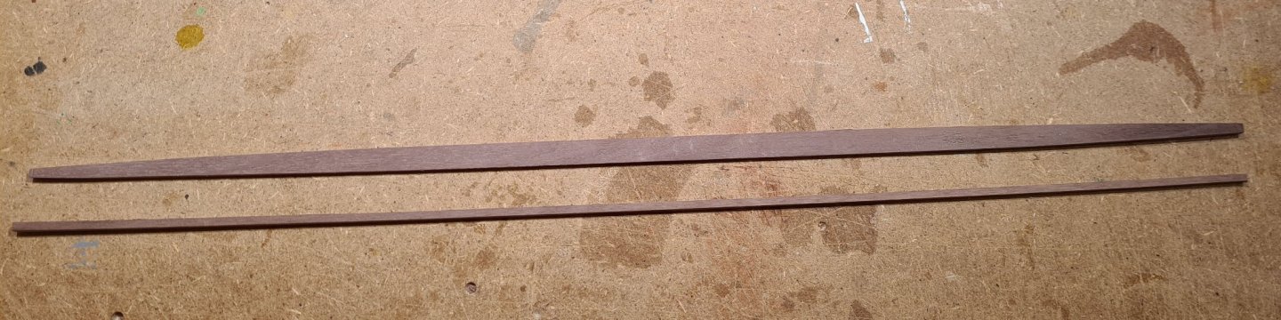
In my previous models I have only used soft wood (mostly Lime, Basswood and Obechi). For this model I wanted a harder wood that is not as easy to damage by clamps etc. I also want a darker wood. I have not decided on the finish I will give to the model in the end, but one option is to simply oil it. In that case I would still want a dark color that reminds of the tarred look of the reconstruction. So my choice for building material is walnut. I have not worked with that before, and still need to learn how it behaves.
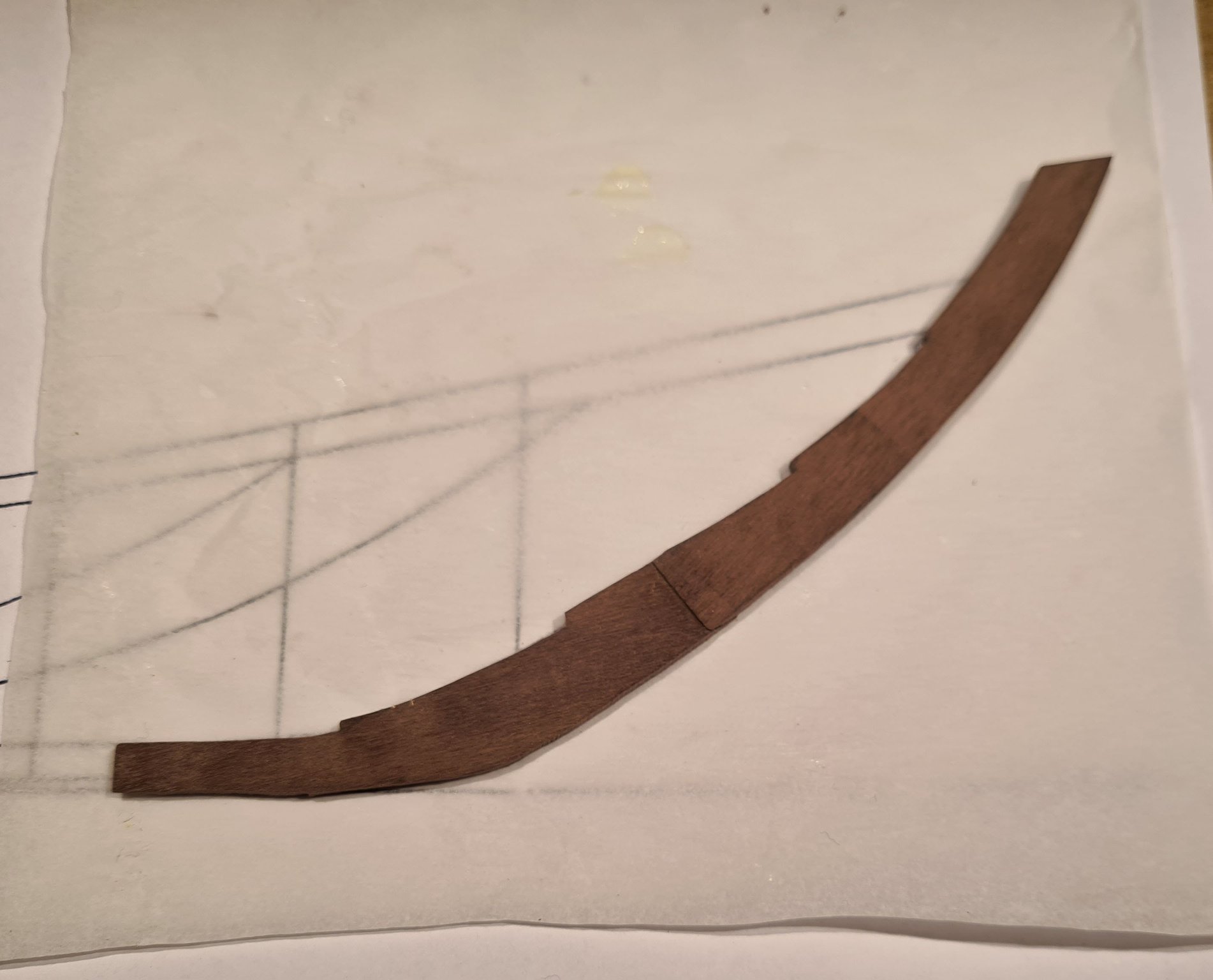
The first pieces I started with are for the keel. The original has a T shaped keel, about twice as wide as it is tall on the widest part under the mast foot. The keel is also slightly curved upwards towards the ends, which means that it would be hard to cut from a single piece. And I don't have a mill, which would more or less be necessary. (In my other build of a Sloop from Roslagen I used soft wood and cut the keel from single piece using hand tools). For this build I have cut the keel in two pieces that will be glued (and plugged) together.
-
I must say that it is quite hard to see the mistakes that you mentioned in the first post. I think that the build looks nice and clean. Especially the deck looks really good in the natural light of your pictures.
-
-
Nice build, when I looked at your images on the other site.
- popeye the sailor and Arjan
-
2
-
Thanks for your input, I think that I need to do a bit more research before I start with the rigging and sail. However, there is still a long time time before I come to that...
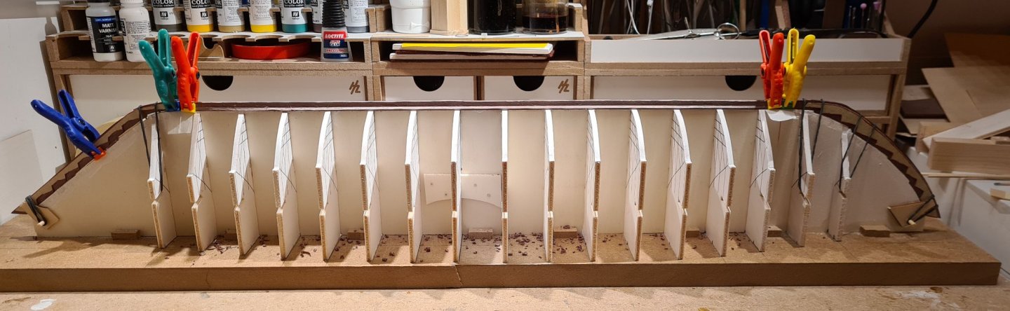
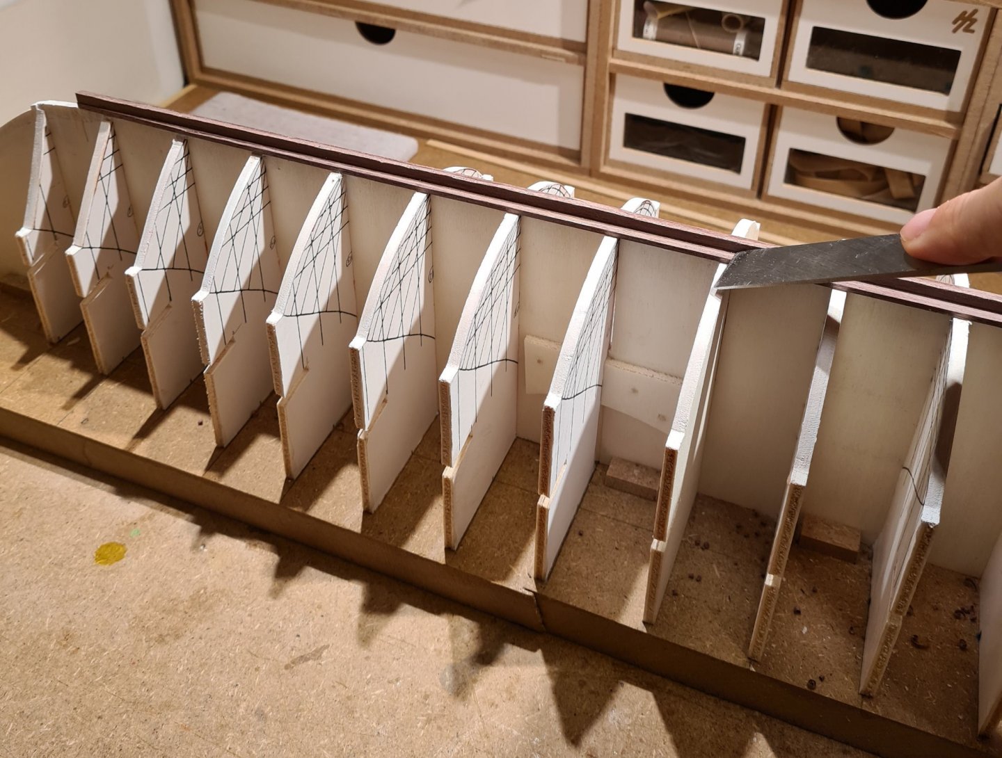
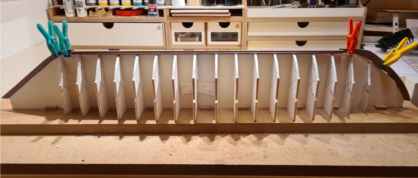
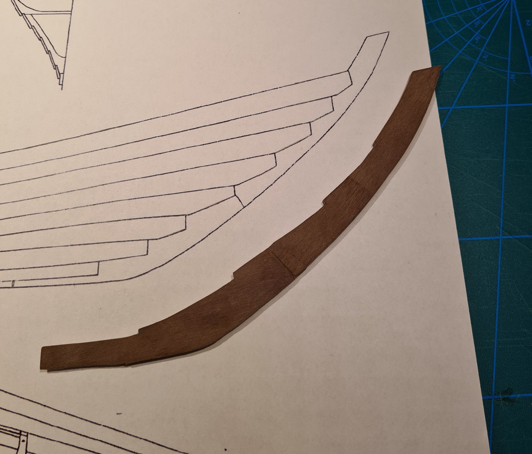
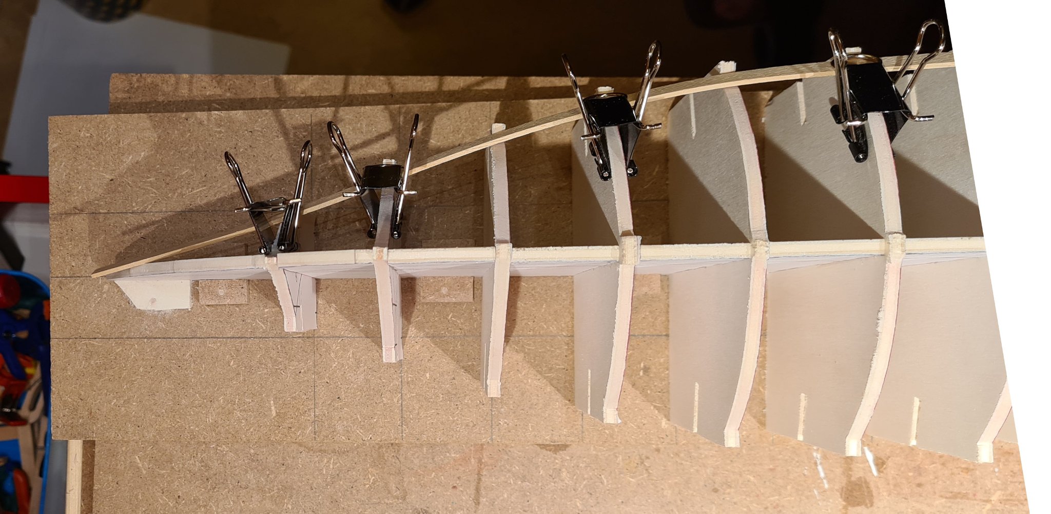
At the moment I'm starting to doubt the reconstruction of the hull. When I sawed out the frames for the build form I observed that the first two are concave rather than convex.

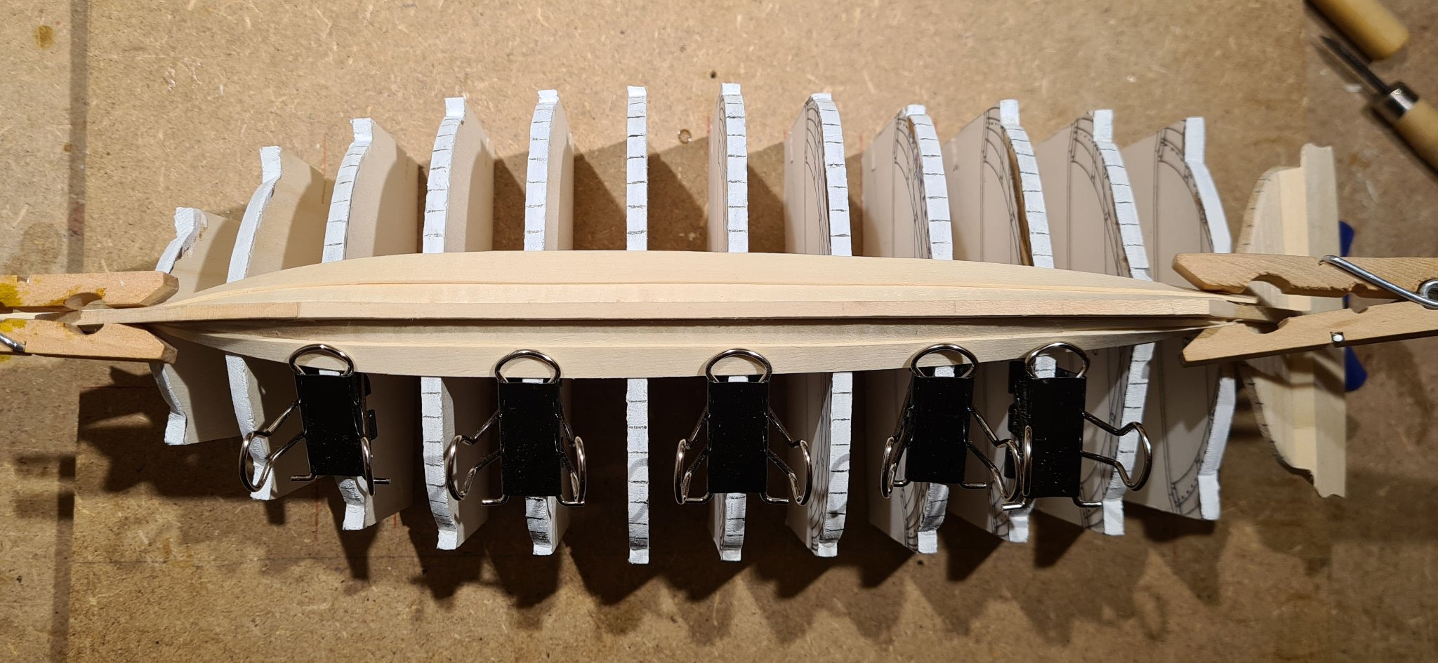
Fitting a strip of wood shows the approximate shape that the bow will have. Note that I have not faired any frames yet, and that the keel part is to wide, which probably exaggerates the concave shape.

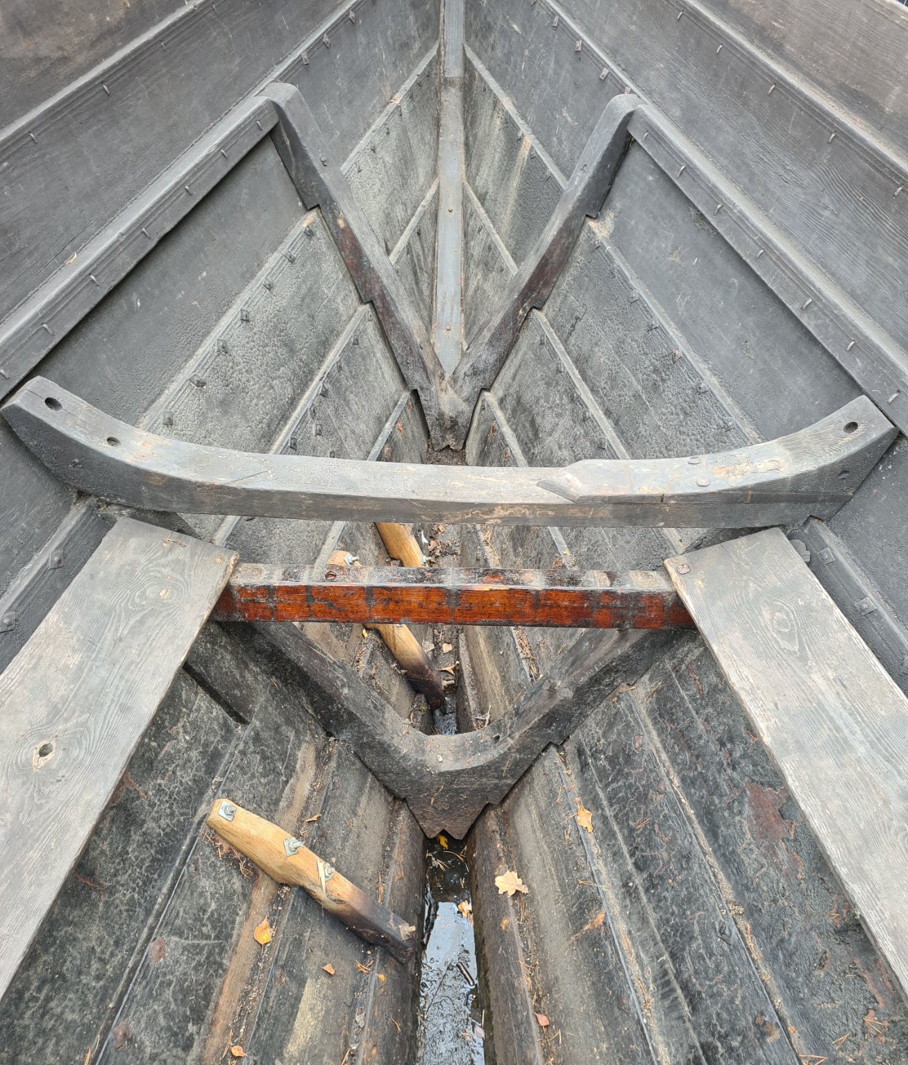
But when I look at some of the pictures from the reconstruction there is some indications of concave frames. (The frames are approximately at the positions of the stations in the body plan.)

I also remember that one of the members of the crew mentioned that the boat builder had problems trying to build the bow according to the reconstruction plans. I imagine that it would be really hard to create the concave shape in a shell first build method. I will now need to study my references again and see if I can find any mention that the boat builder deviated from the plans. If so I will need to find a way to adjust the shape in a similar way in the model. If all else fails I would need to go out to the ship and take measurements.
- thibaultron, Larry Cowden, ubjs and 5 others
-
8


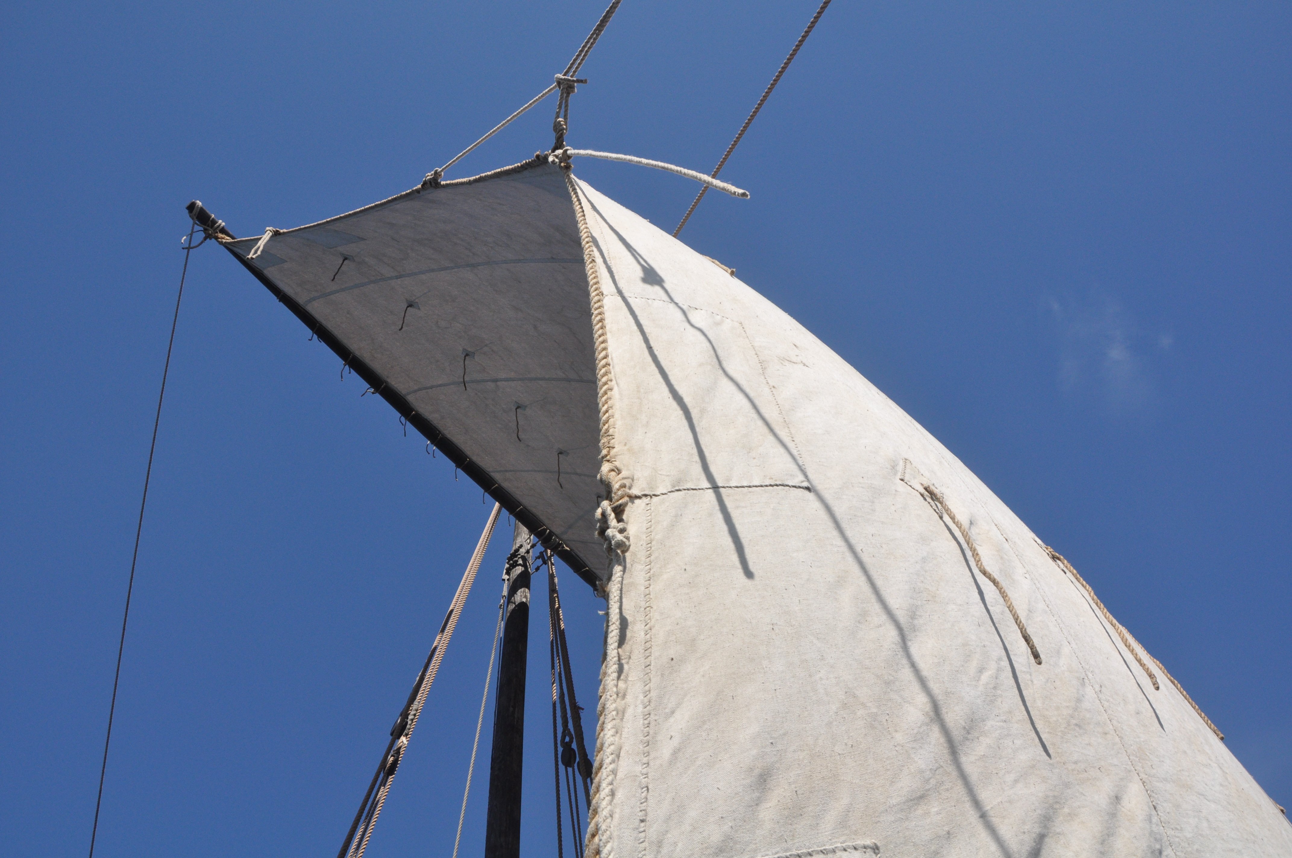
Steel wire or hemp rope on Thames sailing barge circa 1940?
in Masting, rigging and sails
Posted
Thanks for your in depth description of Wills rigging. I did finish my model some months ago, but I hope that others will be able to use the information.