


Kevin-the-lubber
-
Posts
1,232 -
Joined
-
Last visited
Content Type
Profiles
Forums
Gallery
Events
Everything posted by Kevin-the-lubber
-
 Thanks Ian, I got close to what I was aiming for on the bigger bits but less so on the small items, where for me anyway it’s much harder to get a wood effect.
- 444 replies
-
- 2
-

-
- Cutty Sark
- Revell
- (and 2 more)
-
I took a good look at the quarterdeck cabin roof while visiting a couple of months ago and you can see where the edge planks have been patched. They are also shown, in this format, on Campbell plan. Ultimately though I just liked them, there’s not much detail on the model and, for me, they add interest. (Plus they were quite satisfying to make!).
- 444 replies
-
- 3
-
-
- Cutty Sark
- Revell
- (and 2 more)
-
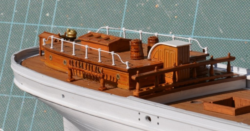
The light this morning is so beautiful that I took a quick break from gardening to grab a picture of the quarterdeck mid-way through final assembly; I still need to finish the water buckets (making wire handles), and trim the pins to length, little jobs that I'm doing when I've had enough of potting, weeding and planting. I'm happy enough with this so far - I'm learning a lot, which is the point, and will do some things differently on the next kit, but as I'm not obsessing over every small error on this one I'm accepting that this is as good as I can do at this point in time i.e. the stanchions don't look nearly as wonky in the flesh but nevertheless aren't perfectly upright! I expected these and the railing to be a nightmare but in the event they were fairly straightforward. I made a little former for the wire rail to get the shape and exact length and the only tricky part has been trying to avoid losing detail through painting.
- 444 replies
-
- 4
-
-

-
- Cutty Sark
- Revell
- (and 2 more)
-
I think you need to orientate them correctly before posting. I always edit mine in MS Picture Manager (other packages are available etc.... but I find this one easiest); first I crop them, then I compress for the web to 'for documents'. You can also resize here, just double-click while editing.
-
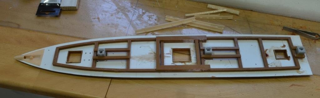
I've more or less finished the deck furniture work now, just little bits and bobs to do before I stow it all away while I work on the hull pinrails (rough versions of which are at the top of the photo below). Photos will follow once I've finished varnishing etc. Meanwhile and just for completeness I thought I'd share a picture of what I did to strengthen the deck, explain why, and see if critique produces better ideas for next time, as I'm already thinking forwards to something similar for the Kearsage. This is the deck upside down. The planked side of the deck is made up of four FDM-printed sections and a small resin-printed section for the bowsprit area, that skin-coloured bit in the photo. The planked deck sections are only 1.3mm thick, which means they are very, very bendy and flexible. I chose FDM because I could print these section dead flat, to get a better finish, get dead square joints and introduce the deck curve through bracing. The white base in the photo is 0.5mm styrene card. This is joined to the planked sections using double-sided tape. The reason for two layers is that it enabled me to butt-join the planked sections dead flat and dead true. I found glue-ing was too difficult: too little glue and the planks would lift at the joints; too much and the glue would get squeezed out, harden and spoil the joint. DS tape over this amount of surface area seems to work just fine. However, that still left me with a very floppy, easily distorted deck which wouldn't have had the rigidity to hold the masts true. With hindsight, I should have committed to making new masts and had them connect to the keel, rather than maintain the short socket method favoured by Revell. Nevertheless, the brown frame in the photo is FDM printed and, being 5mm thick, has quite a bit of rigidity. The deck curve is designed in to the top of this frame. This is made and glued as three sections due to printer size limits. The middle section interlocks so that it doesn't rely entirely on glue for strength. I resin-printed the mast sockets and braced these further by glue-ing additional FDM printed bars to the sides of the sockets and framework. All told this has created a fairly solid deck, with just enough give in it to flex to the fore-to-aft curve of the hull and, most importantly, the masts are held firm and true. Not shown here, but I've boxed in the three hold areas to pretty it up when looking from the top; though not yet settled on whether to fill these with cargo or leave them as a faux deck, or even cover them up with gratings. I certainly wouldn't claim this as a great method, just one that got around the limitations of 3D printing to give a fairly decent, low cost end result. On to the pinrails and railings now; I'm expecting this to be tricky to get right.
- 444 replies
-
- 2
-
-
- Cutty Sark
- Revell
- (and 2 more)
-
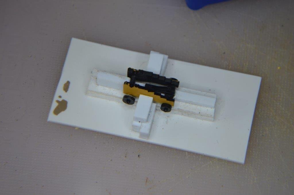
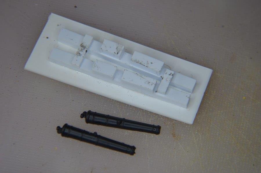
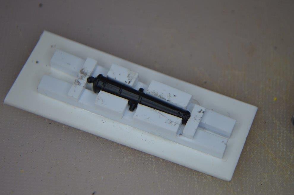
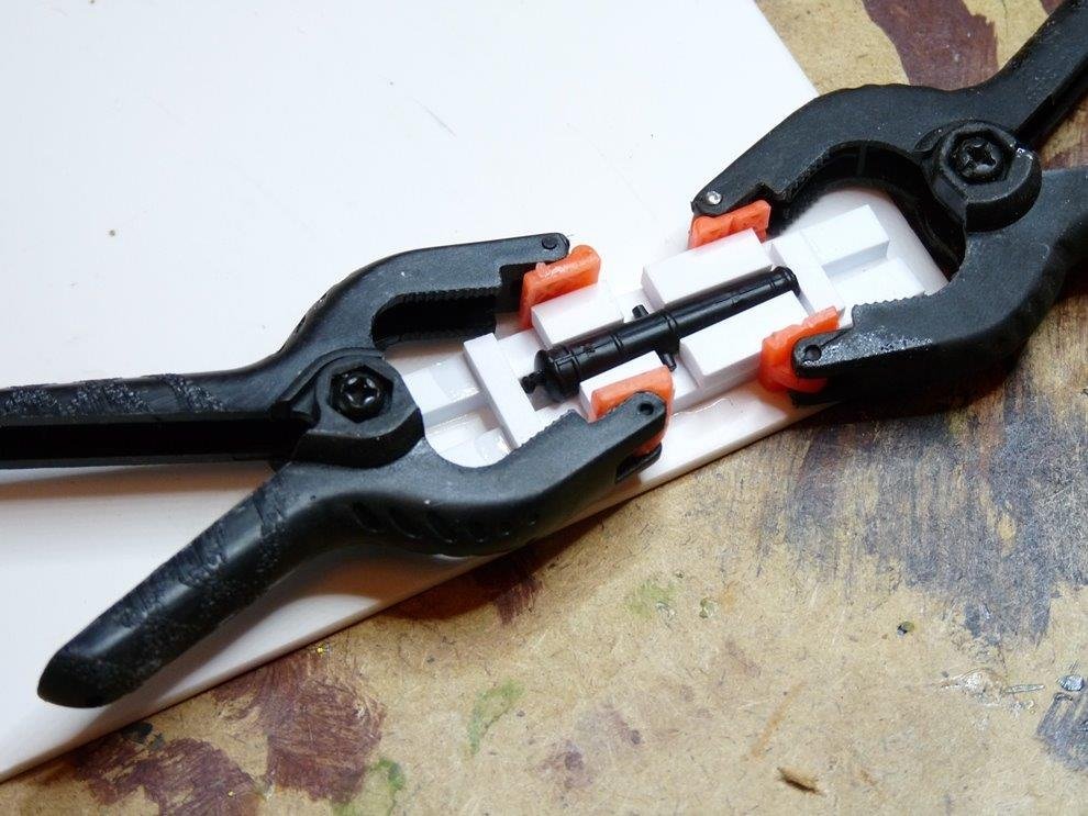
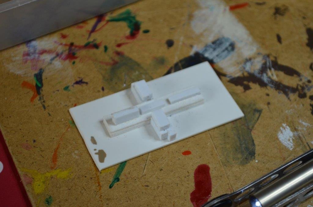
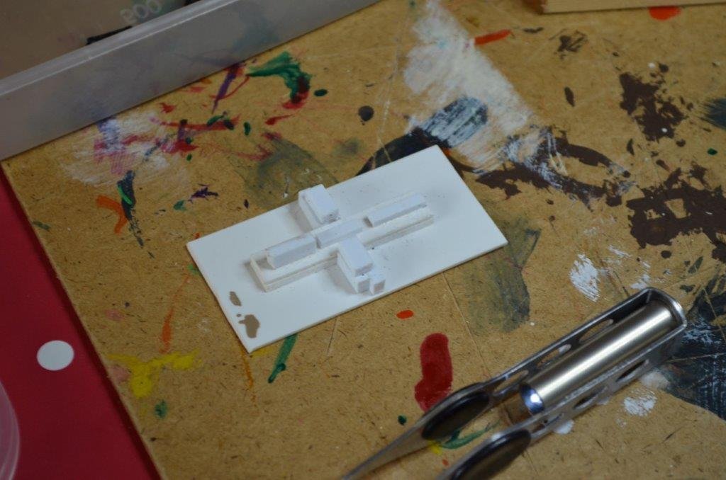
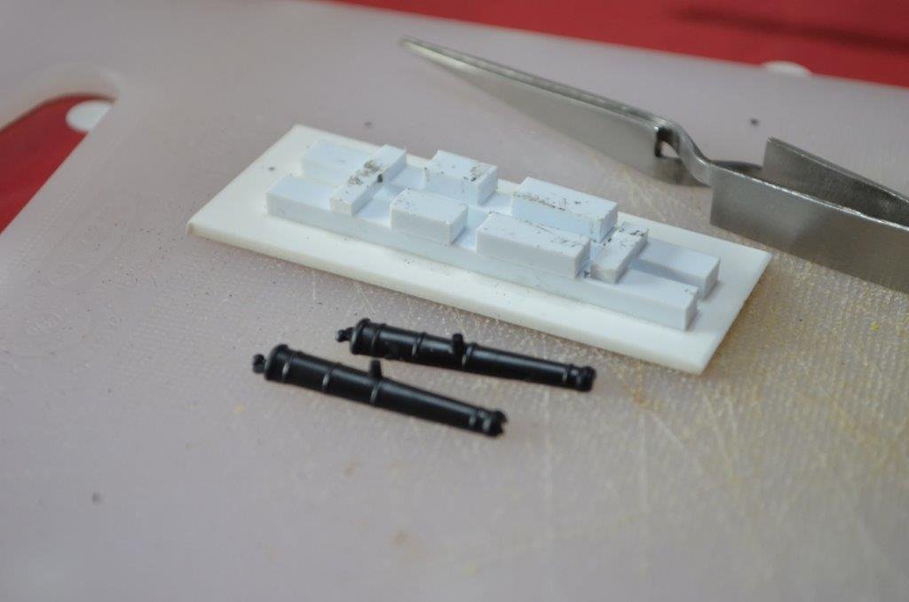
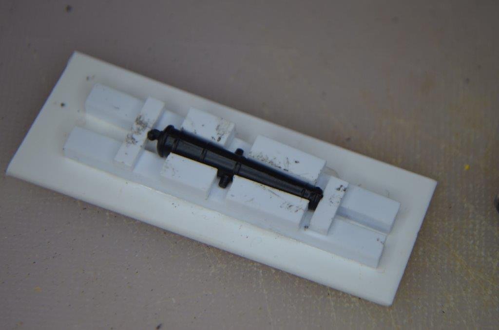
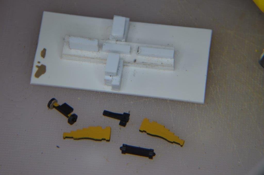
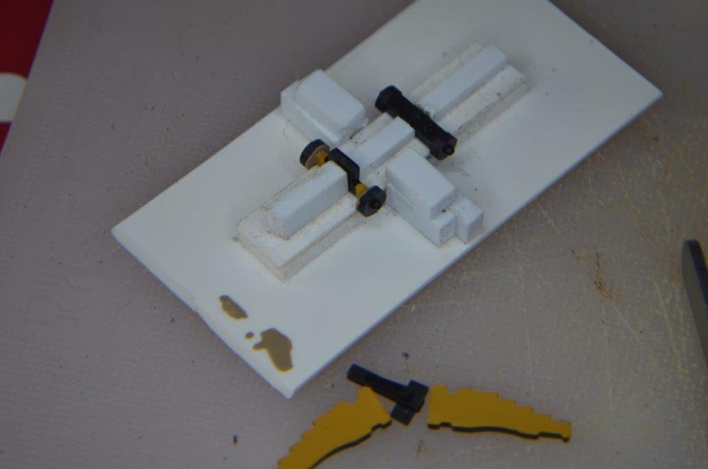
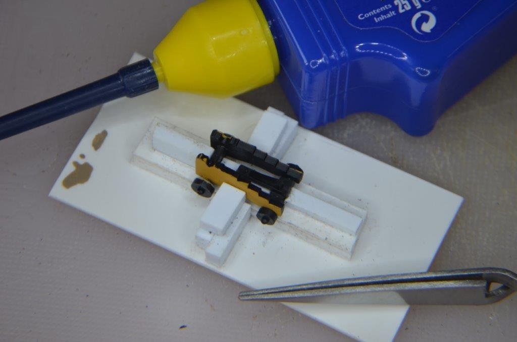
Hi Jeff, here are various photos of the jigs I knocked up when assembling the cannons about 10 years ago (is it really that long!). These were made with styrene, there's nothing very clever or technical, I just cut and filed to size to hold everything in place. There were two or three lessons learned that I'll mention; 1: after a while, you'll almost inevitably get styrene glue on the jig and it'll get spoiled(-ish)/soft(-ish), so it might be worth making 2 or 3 of each. Or use something other than styrene. Or be better at applying glue than I was 10 years ago 😊 2: I mistakenly thought the carriages would have an inwards camber bottom to top: keep an eye on that, they don't. 3: the quality of moulding is superb; the cannon halves aligned true every time, as did the carriage parts. I hope this gives you the general idea. I'm sure I'm not alone in saying I'm looking forward to seeing your build develop, the Victory is such an interesting kit to spectate on, and everyone has their own take and way of doing it.

-
This thread is displaying strangely today so I can’t see whether I’ve already said this, so apologies if I’m repeating. Two or three months back I did a load of upgrades to my ender 3 printer which have pretty much transformed the experience from endless frustration and disappointment to an easy, reliable go-to for many things. Firstly I bought a filament heater for about £30. I believe this makes a huge difference to bed adhesion and print finish. I then replaced the bed springs for about £5. I haven’t re-adjusted the levelling since fitting these as the bed simply doesn’t move anymore. Though I also fitted the auto-levelling gizmo, which might contribute. I then upgraded the motherboard to the latest version, along with a silent fan for the power supply. Printing is now virtually silent instead of all that whizzing and whirring. In fact it’s so quiet I happily have that running during the day while I’m sat next to it in zoom meetings for work. All told I guess I spent about £100 and it was well worth it. nb. the filament heater makes my spool holder redundant as it has rollers. Worth mentioning that I linked the heater box to the printer with a short piece of spare Capricorn Bowden tube so that it is an almost sealed system, and I run the heater all the time I’m printing.
- 460 replies
-
- 5
-
-

-
- Finished
- Flower-class
- (and 1 more)
-
3d printing process
Kevin-the-lubber replied to henrythestaffy's topic in 3D-Printing and Laser-Cutting.
I can believe that. After a few months I had to clean and re-grease the rails on my Mars as it was sticking so I expect there's a point beforehand where the resistance might adversely impact. I used lithium grease, which reminds me that I must buy some proper 3d lube as my saturn is probably due for some maintenance. I think you can use whatever resin you wish, you just have to dial in the correct settings. One thing I'm noticing is that different brands have a different tolerance to non-ideal ambient temperatures. I have to extend the curing time for thin, runny resins compared to the thicker elegoo compounds. -
I still wouldn’t know how to really plan a build, but I tried something on the Cutty sark that I think works well for me: I test fitted almost every single part before doing anything else, to get a feel for what goes where, how things interact with others, what parts I would remake and so on. I labelled each part or subset and keep them in little ziplock bags. I did also buy a second kit off eBay but haven’t needed to dip into that yet. Even so, I would still do a better job if I started all over again.
-
The current colour kind of depends on the light. It’s supposed to be a light yellow against dark grey, though appeared vaguely cream with pink tones to me. But who am I to argue with the experts and I’ll take their word for it that this was the colour scheme at trafalgar. However, there are 70 odd others coats and my guess is that, within reason, any shade of yellow will have had its day. Just pick one you like!
-
Me next! I’m sticking with the yellow ochre. When I visited what’s left of the ship last year I found the ‘original’ flesh colour a bit too nondescript to be even tempted to switch. But as Ian says, seriously, do whatever pleases you. Ian’s spreadsheet is mighty useful - I did use it Ian, based my deadeyes and blocks on that but I just haven’t got that far yet to be using blocks and tackle! A tip re’ the Vallejo yellow ochre. If you’re going to be air-brushing it, add a generous dose of Vallejo flow improver. Of all the Vallejo colours I’ve now used, the yellow ochre was the one that gave me the most headaches. It could be that my airbrush, being cheap, is more susceptible to clogging but flow improver makes a big difference. You look like you’re going to be another fast builder, like Bill, and I too will enjoy seeing yours come together. I don’t think I’ll be going back to mine for maybe another year or two as I want to build the Kearsage once I finish the Cutty Sark.
-
Quite true, Allan. I should think very few modellers are ever entirely satisfied with their efforts.
-
Marc, I spent a bit of time doing colour tests; in fact the best result for a near teak effect was a sand colour primer, raw sienna base, burnt sienna wash and peat ink, but this really clashed with the deck so I skipped the burnt sienna. I’ll settle for this, especially as I don’t yet have the skill to do it better.
- 444 replies
-
- 3
-
-
- Cutty Sark
- Revell
- (and 2 more)
-
Lovely work. I think all of us relative newbies have to swallow the odd mistake, accept that the experts went through it too, or be forever fixing small errors at the risk of losing motivation. Another way to look at it (my way now) is that 99.9% of the people who see your model in the flesh won't know a rudder from an udder and will only see the beautifully crafted end result.
- 129 replies
-
- 2
-
-
-
- Bounty Jolly Boat
- Artesania Latina
- (and 1 more)
-
Glazed portholes this evening, and a first go at a more true-to-life binnacle. This one is too big, 20% smaller is about right and awaiting painting. Re' the portholes, for every one in the cabin there are 5 pinged around my workshop, never to be seen again. But I made loads of spares.
.JPG.c6b57e4700ba87d70228ab509fe2ef96.JPG)
.JPG.859b27b5d45ad42640099adcf127a114.JPG)
- 444 replies
-
- 5
-
-
-
- Cutty Sark
- Revell
- (and 2 more)
-
That's a good tip about the leadwork for the windows, I'll try to remember that.
- 2,699 replies
-
- 8
-
-
- heller
- soleil royal
- (and 9 more)
-
It sounds like the S-grooves worked? nb. You really have made a nice job of the planking, if you'd said this was your 40th plank on frame I for one would have thought 'oh, so that's how it turns out when you've learned how'.
-
I'd recommend starting a build log here straight away, many of us are relatively new or returning after a long hiatus and people here are hugely supportive and helpful. The instructions are on the main page. Re' wooden blocks, I was very impressed with the samples sent to me by Hismodel when I bought some PE from him recently. One other 'must have' book is John McKay's 'The 100-gun ship Victory (Anatomy of the ship).
-
By the way Bill, you shouldn't be so hard on yourself. As I'm sure you're going to find when you have it finished and on display, you are going to hear a lot of 'wows'. You've made some very good individual taste choices that, in my view, make this a unique and very appealing build. And one more 'by the way': you do realise, don't you, that a little ways down the line we're all going to be asking you the same questions you've been asking Ian, so don't plan any long vacations! Ian - I hadn't thought about that (the CS climb). I'm sure they'll have a hoist... Personally I enjoyed Aubrey/Maturin the most. It's rare that I hang on to books once read but for me, that set are keepers. You're right though, they'll make more sense in places with ship modelling knowledge.
-
Re’ Dr Maturin, very few as I remember! But I’ll make a note to count when I next re-read 😀. Climbing overhangs on a rock face firmly planted in the ground was bad enough, nothing but nothing would persuade me to do this on a ship swinging in the wind.
-
Now I understand your problem better. A question - is the PVA peeling off easily? And is the stain oil-based? I’m wondering whether this is the issue, that the stain has created a barrier. Although I’ve glued countless bits of timber I’ve never stained it first as I would always be wanting a fresh, clean surface but also because my (furniture) joints sometimes need a little bit of tidying and blending. If it was me I think I’d do a little testing with a fresh bottle of PVA at this point, glueing stained/unstained. Either way, your plan to carve small grooves sounds like a good one. Alternatively, if there’s enough meat, how about drilling a load of shallow holes along each mating surface and, to go the hole hog, pop in some dowels. Just about anything will do but cocktail sticks spring to mind. I don’t have any experience glueing wood with CA so don’t know if that permeates better than PVA. Gorilla glue also has its uses so long as you can clamp parts together, but it can be messy. And to go a little left field, industrial mastic-type adhesives just might do it; I’ve never used them to actually glue wood together but I’ve sealed stained and varnished window and doorframes without issue and could imagine it working. The boat itself looks wonderful and I feel your pain. To have produced such a lovely item and then see it fall apart in my hands would be heartbreaking.
-
Looks eminently suitable, Bill. And it remains fascinating to see you working through this, bit by bit. The sheer amount of labour required for rigging gets completely lost from view when someone simply does a “ta-da” reveal and for beginners like me the step by step coverage is going to be invaluable.
-
That’s fascinating. I imagine it costs a fortune. Depending on how strong the printed objects are, it does have relevance to modelling: for 1/100 scale I can print blocks down to about 2mm but anything smaller I.e. 6” blocks, are technically challenging. Nano 3D probably opens up a whole world of possibilities for models at, say, 1/700 etc.
-
I think some pieces are better made using resin and others using filament, but neither are ideal for every part and in some instances, e.g. masts and spars, neither are particularly suitable at all. Resin gives much better fine detail but filament is better for structural strength, at the expense of surface finish. Personally, I won’t be too surprised if I eventually find myself using 3D printed for a frame and detailed parts but with wood planking for the aesthetics. In any case I’ll follow yours with interest. 3D seems to be coming into play quite quickly, with more and more model makers heading in this direction.
