
Model Mariner
-
Posts
95 -
Joined
-
Last visited
Content Type
Profiles
Forums
Gallery
Events
Posts posted by Model Mariner
-
-
-
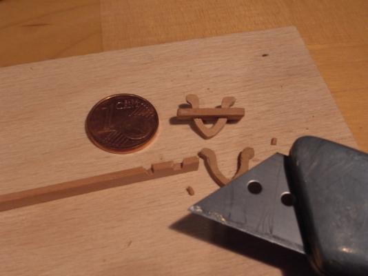
If there were not fingertips in one of the pictures I would have asked where you have got the hugecent coin from!
Very nice work as always.
Klaus
- cog and aviaamator
-
 2
2
-
-
-
Right Jan, it should read 645mm, thanks for the note. I have corrected the typo in the previous post
Klaus
-
Hi Charlie
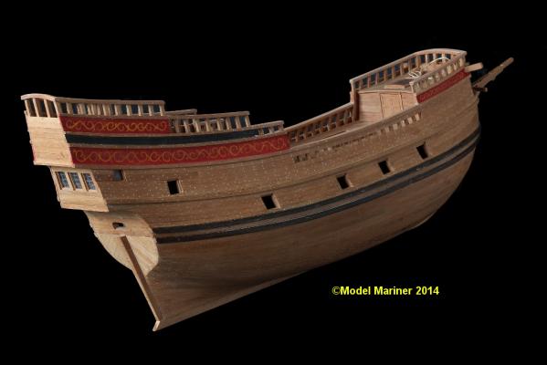
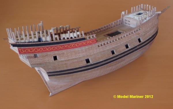
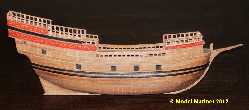
lenght of the hull (including beakhead) is 544 mm / 21 3/8"
lenght including bowsprit is 645 mm / 25"
height (not considering an eventual flagstaff) is 504 mm / 19 7/8"
Klaus
-
I would vote for natural
Klaus
-
Thanks for the comments and likes folks

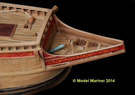
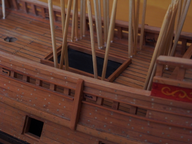
I have glued in the kevels for the sheets of the main course and have installed some sheave blocks for the sheets fo the courses and the spritsail as well as for the tack of the main course. Having done that I intended as next step to build in the half deck but then I decided to treenail also the deck planks, so there's another 750 plus treenails to put in. For these I drilled holes 0.6 mm diameter and glued in the tips of toothpicks:


Before closing the half deck I intend to belay the sheet of the main course on the respective kevels under the deck because these are not easy accessible later on.
The sheets and tacks are cable laid rope which is not (or hardly) commercially available in the diameters I need, for this reason I will make my own ropes.
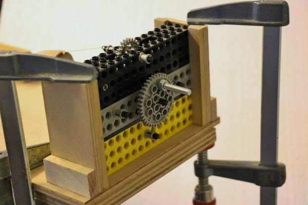
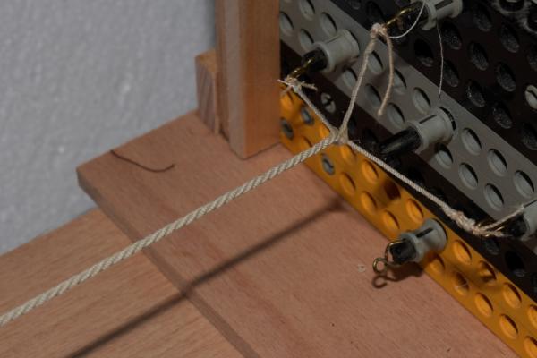
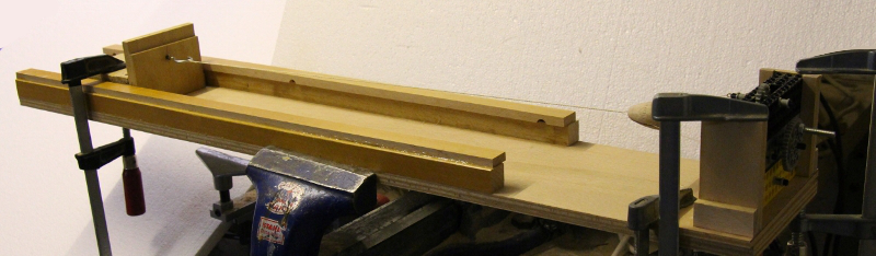
Rope making:
I have made a simple rope-making machine, the planet gear for the looper is made by means of Lego components. I made 4 hooks to be able to make three as well as four stranded rope.

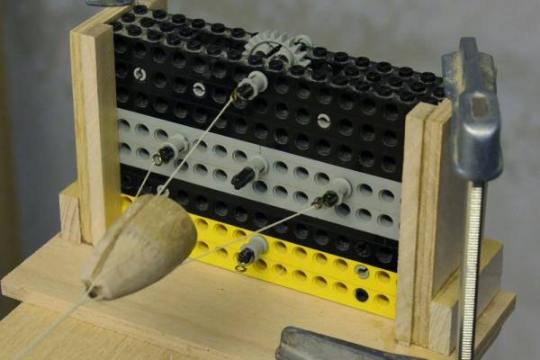
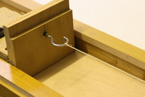
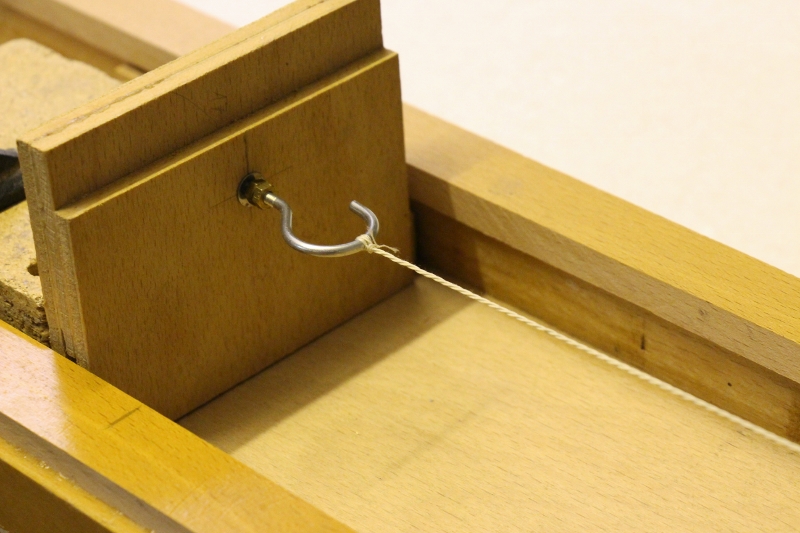
The traveller is simply an angle made up of plywood with a hook which is mounted in a way that it is easily rotatable and the top a wooden cone with some slots in it.
I prefer to fix the looper with clamps rather then screwing it on permanently because this gives me more flexibility to produce ropes of whatever lengths I want to produce.
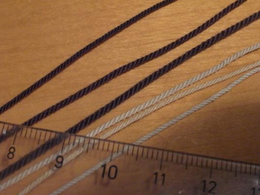
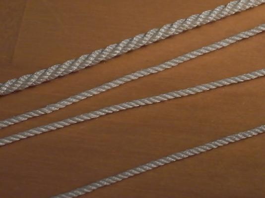
I have started now test using different kinds of thread in order to find out how many threads of which diameter I need to get the required various ropes.
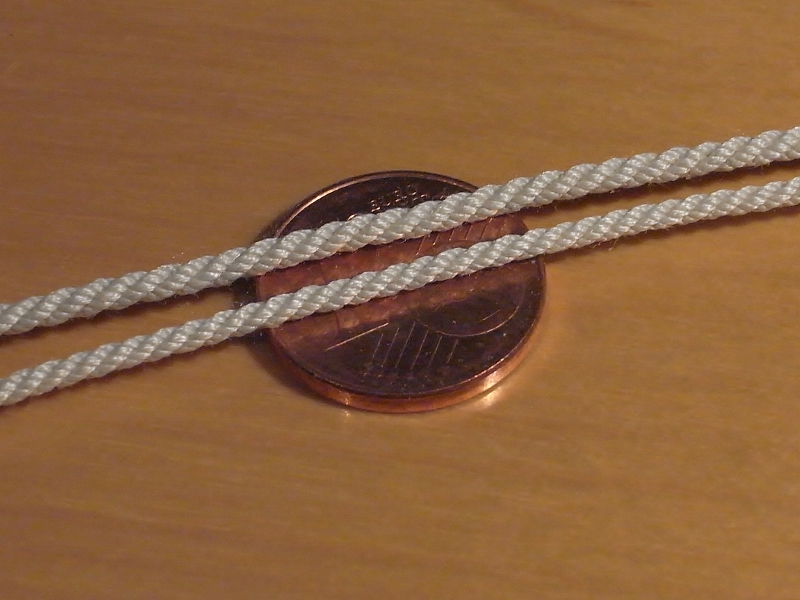
The next picture shows some (test) hawsers of different diameters, all laid left handed (although hawsers are usually laid right handed):
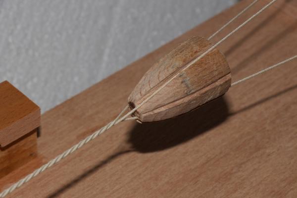
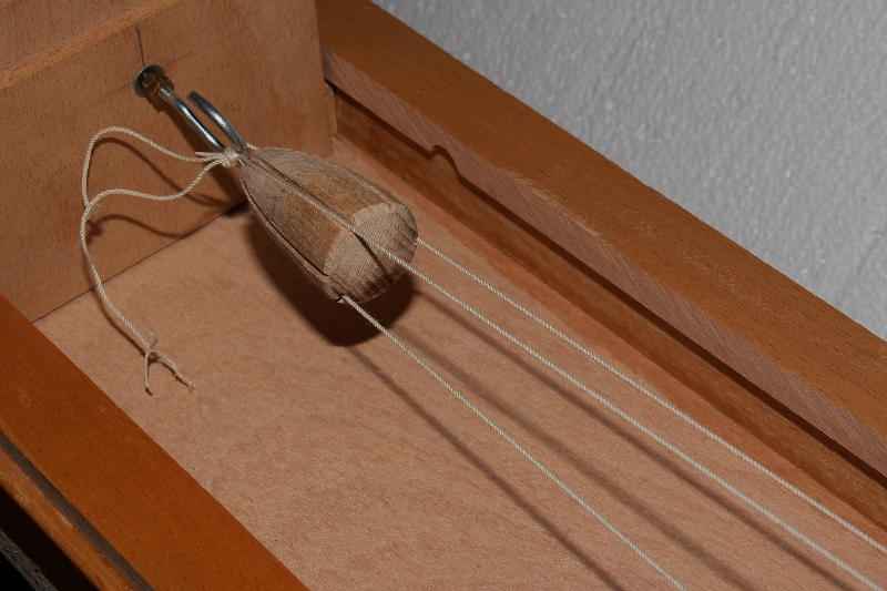
Making of a cable:
For those who are not familiar with the different kinds of ropes: a cable is a 9 stranded left laid rope made of three right laid three stranded ropes (hawsers)
The three hawser attached to the hook of the traveller in the grooves of the top, the hawsers are not yet twisted

the cable starts to build up:
the finished cable at the looper:
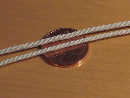
This is a cable (approx. 1.7 mm diameter) and the three hawsers which are used to lay it.
2 cables with diameters 1,7 and 1,4mm:
Klaus
-
Beautiful model, very nice work!
In case you have not noticed: a lot of photos on pages 5 and 6 are not visible. It would be nice if you could re-post them.Klaus
-
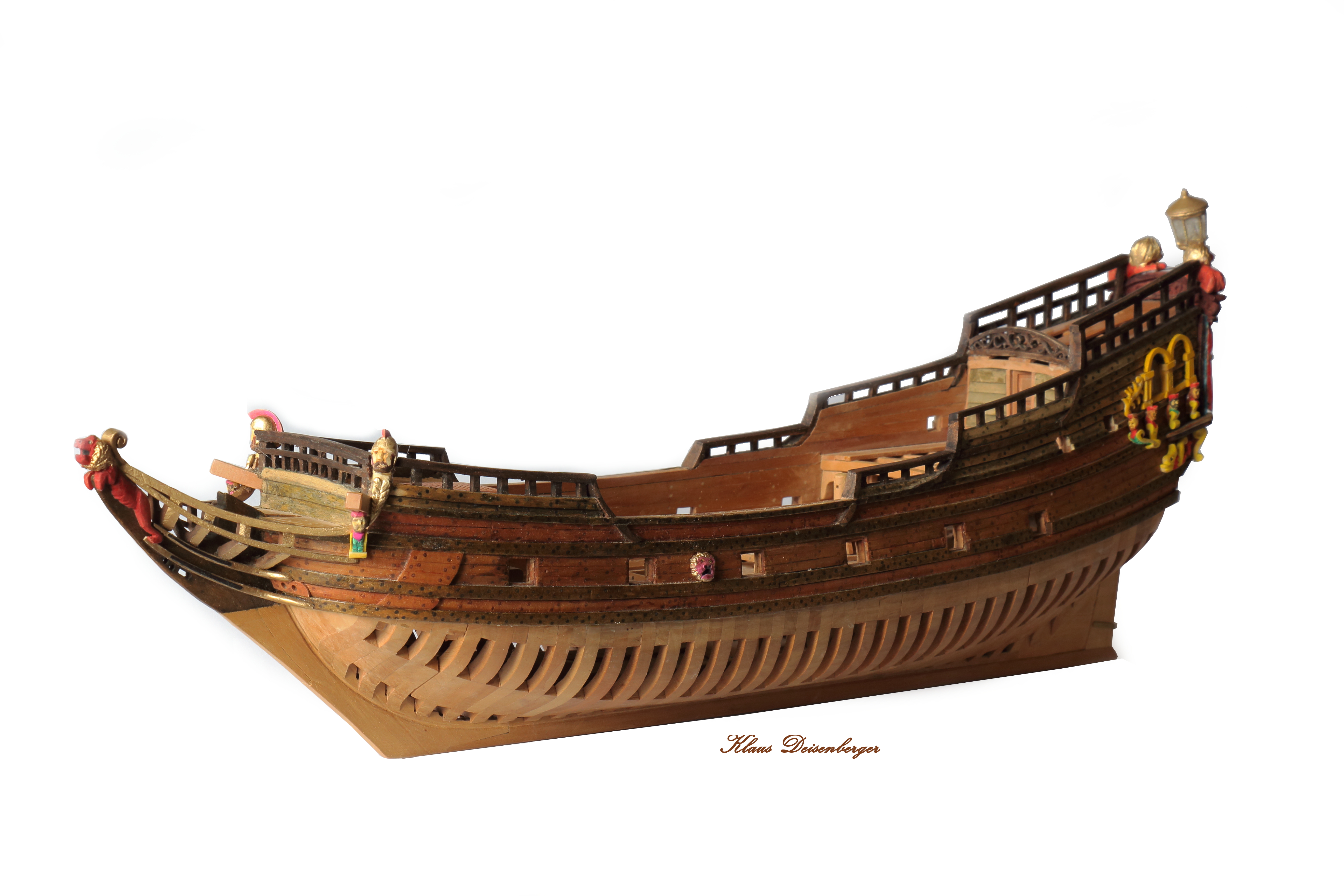
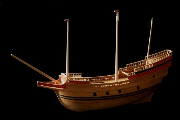
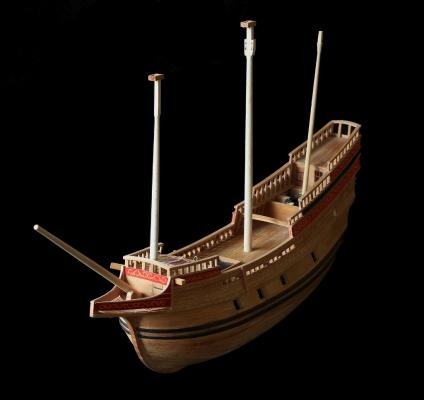
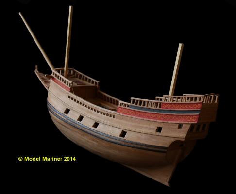
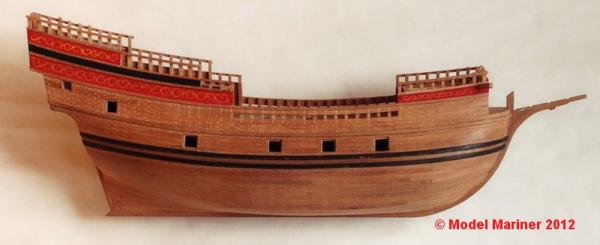
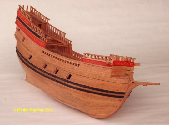
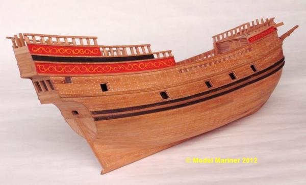
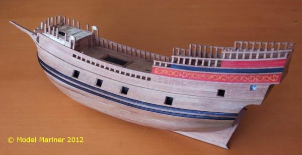
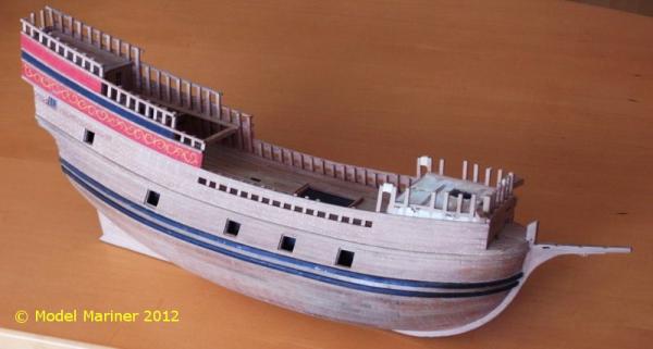
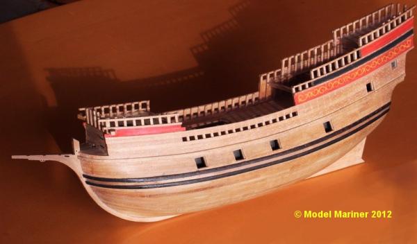
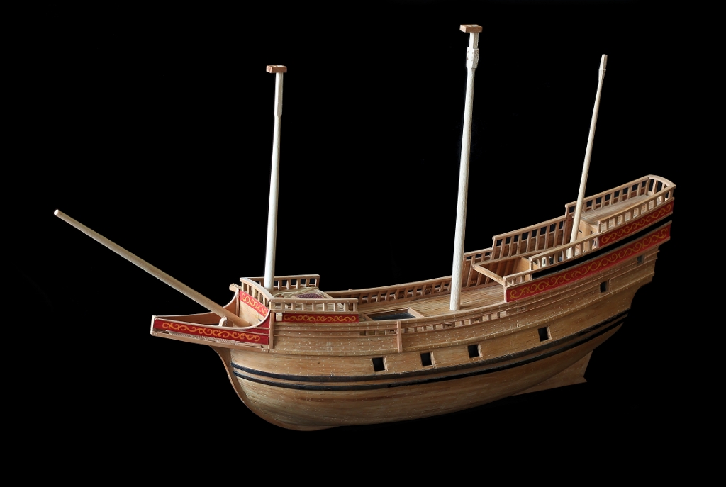
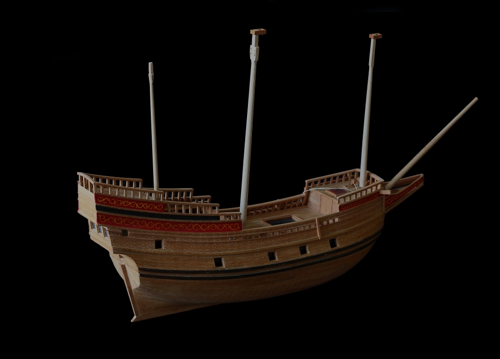
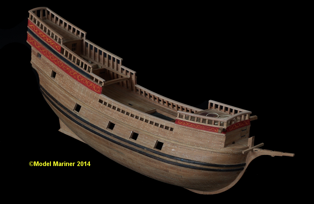
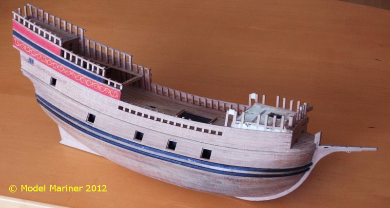
Current status of my model:
The lower masts are just put in temporarily, their angles are not yet correct


Klaus
-
A lot of small stuff is required now, eye bolts, kevels, a capstan etc. and I have started to produce these.
Eyebolts:
I made eyebolts by twisting brass wire (0.4 mm dia) around a 0.5 mm steel bolt. The twisted part is approx. 0.6 mm thick:
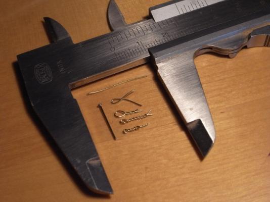
I was not really succesful when I tried to make smaller eyebolts but I think for the scale 1:64 I can live with this size, this is what one of these eyebolt look like when set into an 0,6 mm hole:

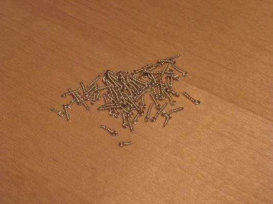
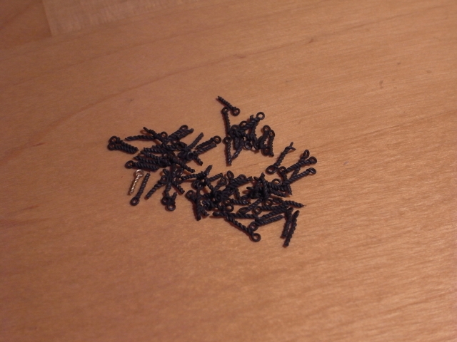
I made 75 eyebolts to start with
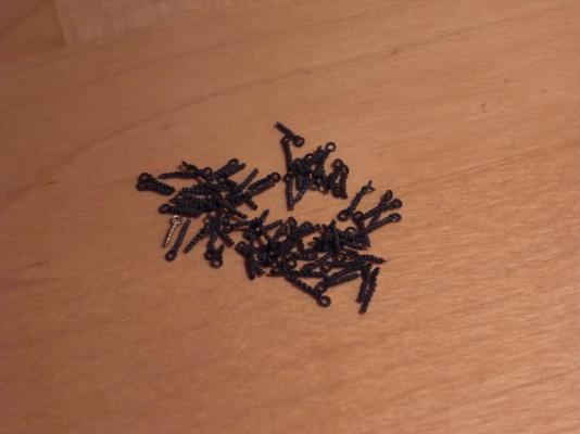
these are the same ones after putting them for approx. 5 seconds into a metal finsiher (Brass Black):
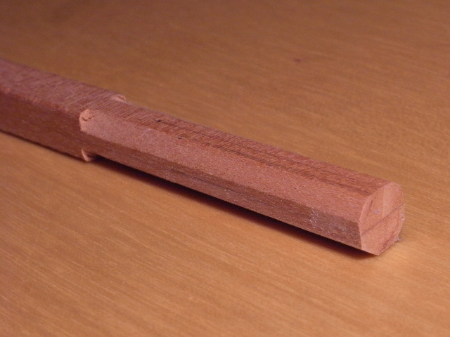
The capstan:
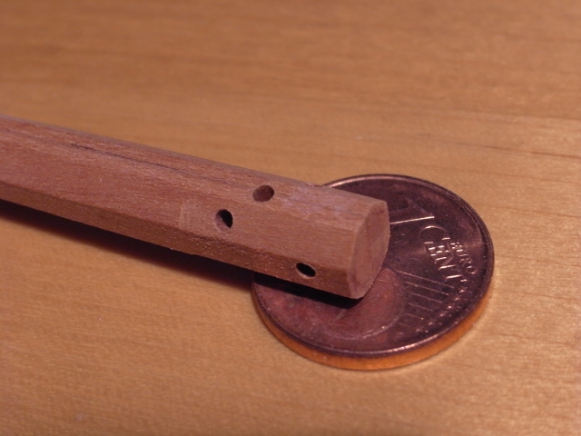
according to Goodwin capstans had an octogonal shaft in the early 17th century
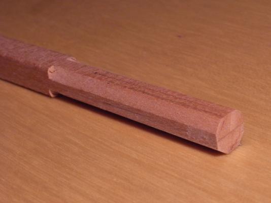
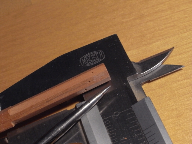
I have marked the holes for the spokes on the shaft
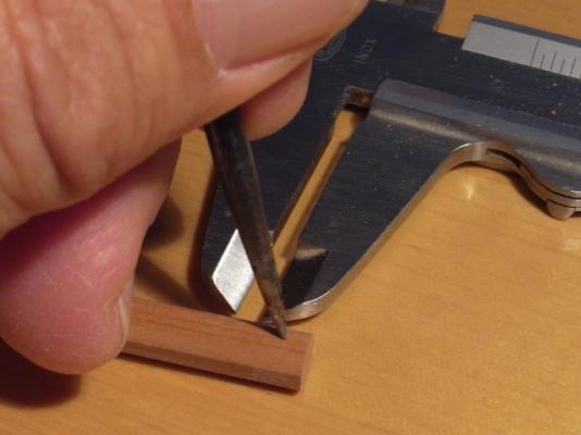
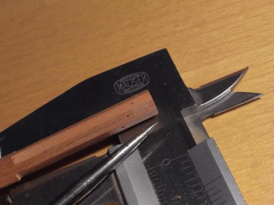
then I drilled round holes which I brought afterwards to the required square shape by pushing in the tip of a nail which I had filed to a sharp square:


Whelps and chocks are glued to the shaft of the capstan (a lot of tiny corners to be cleaned
 ). The picture shows also the whelps for a second capstan (for another model), some kevels and one of the required chesstrees:
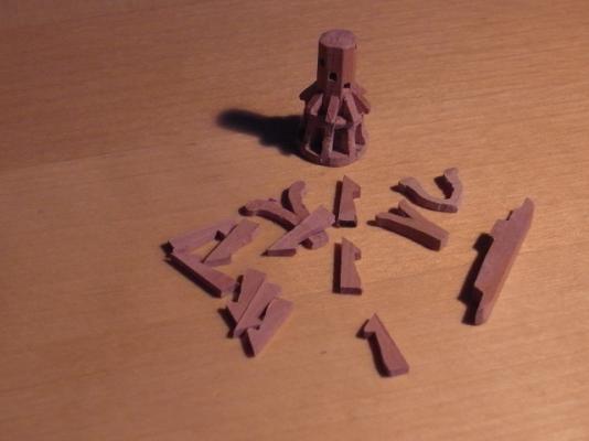
Rails and chesstrees:
The last rails have been added to the hull:

The chesstrees are not yet glued on ( the holes for the main tacks are not yet drilled into them).
Kevels:
8 kevels are required in the waist for the main sail tacks, main sail sheets, fore sail tacks and tacks of the spritsail
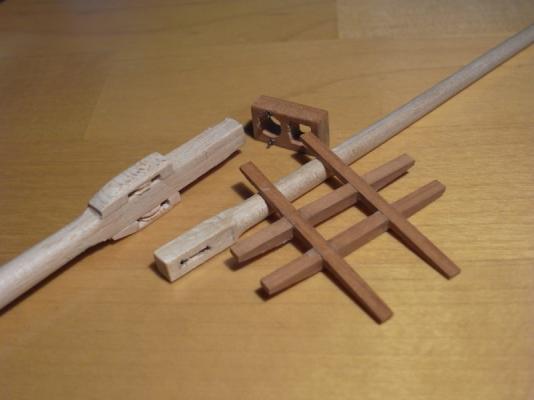
Masts:
Although there is still a lot of work to be done on the hull I have started to make the masts. The picture shows the head of the main mast, the cross trees, the cap and the heel of the top mast:
Klaus
-
Congratulations for finishing this beautiful model, Ilhan!
I hope you have already plans for the next project and I'm looking forward to a respective build log!Klaus
-
Thanks for the nice comments and the likes
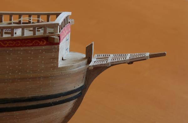
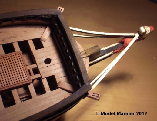
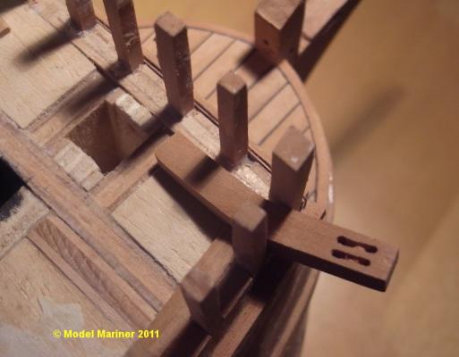
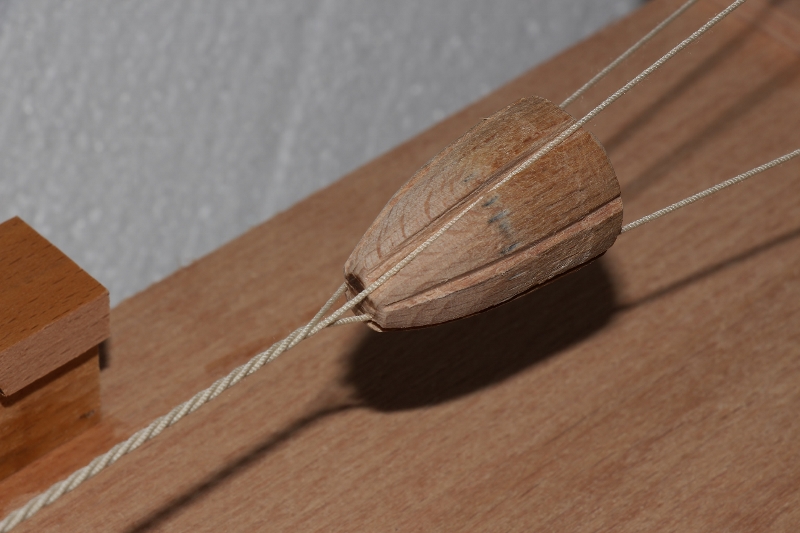
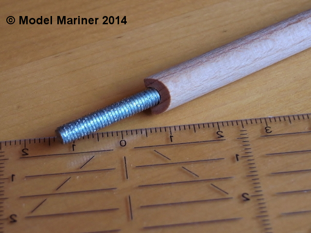
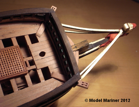
I'd like to go back once more to this picture which I have shown already in my last post, which shows a piece of threaded rod set into the hull at the position of the bowsprit:
The reason for this threaded rod is that I failed to make a decent funnel (I hope this is the correct English term for it) to insert the bowsprit as I did for the masts. I had provided a hole but it was too small and at this stage I found that it was more than difficult to enlarge it to the correct diameter exactly at the required angle. So I had to think a little bit how to solve this and came to following solution:
The bowsprit was already made long enough to be set approx. 50 mm (2 inches) into the hull. I cut it at the position where it is suppossed to enter the hull and I drilled a hole 5 mm dia and about 50 mm deep. The cut had to be made in a way that the bowsprit fits at the correct angle into the angle between the vertical bulkhead and the nearly horizontal deck:

Then using a file I enlarged the hole in the hull to a diameter a little bit smaller than the diameter of the bowsprit. I cut then a piece of 5 mm threaded rod to a length of approx. 3 inches. This was pushed into the hole in the bowsprit (not yet glued), over the half sticking out I wrapped some paper soaked with adhesive until it was thicker than the hole in the hull. Then I pressed this into the hole in the hull, fixed the bowsprit at the correct angle and had just to wait for the adhesive to harden.
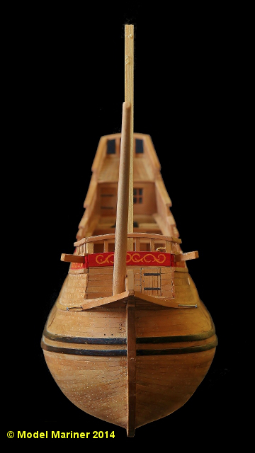
The step of the bowsprit is at the starboard side of the foremast but the tip is supposed to be at the centerline of the ship.
In order to align the bowsprits tip with the masts I put square rods into the holes for the fore and mizzen mast, so I could set the bowsprit in line with these dummy masts by looking at the model from the front and from behind .
The threaded rod sits now tight in the hull, and I can take to bowsprit off and put it on again when required.

I hope this description is not too confusing but I guess with help of the pictures it is clear what i did
Klaus
-
...Only another modeler can appreciate the feeling we get in our gut at this point...
Well, I know the feeling too:
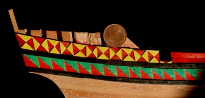

What you have achieved with your decoration looks quite good to me, looking forward to seeing it on your model. Keep the pictures coming!
Klaus
-
That's a very nice model of Gorch Fock, Nils. Beautiful work!
Klaus
-
-
Thanks for the likes, it's always good to hear that others enjoy ones work
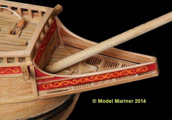
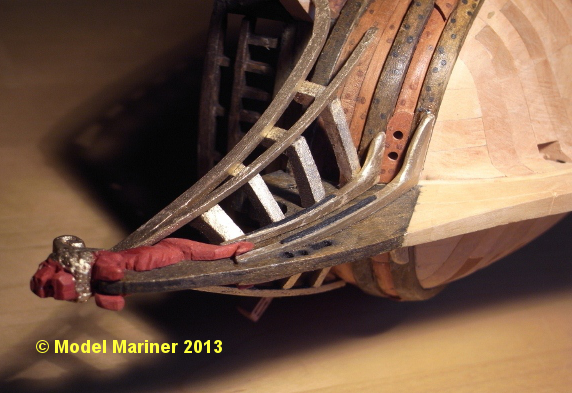
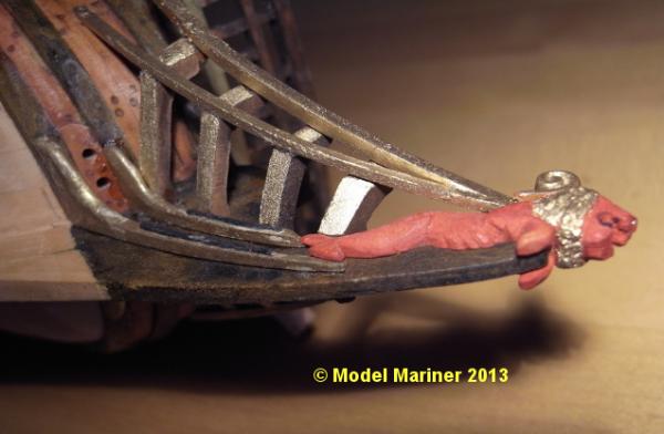
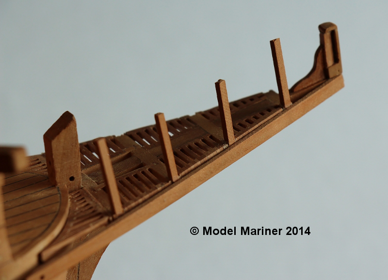
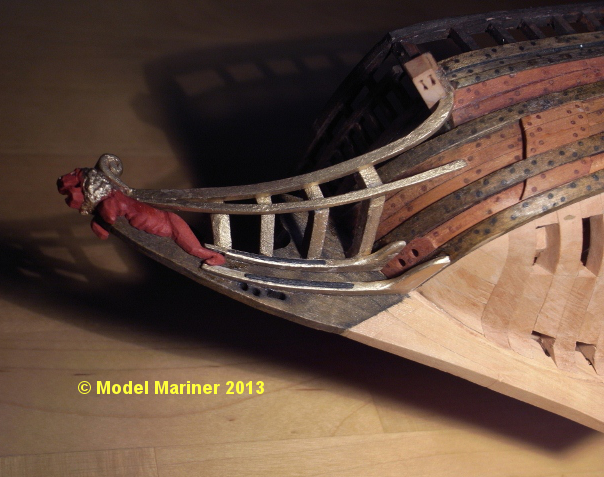
The head:
I guess the following pictures are self explaing. so not much description is required: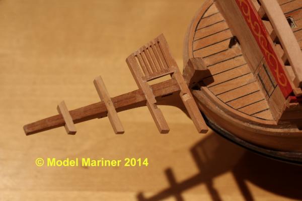
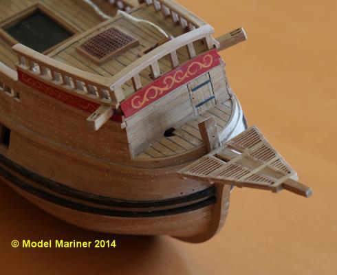
When gluing these vertical timbers on to the brackets at this stage I was a little bit too optimistic, most of them broke later on when I was working on the model and I had to use a different approach:
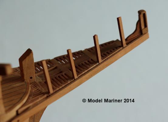
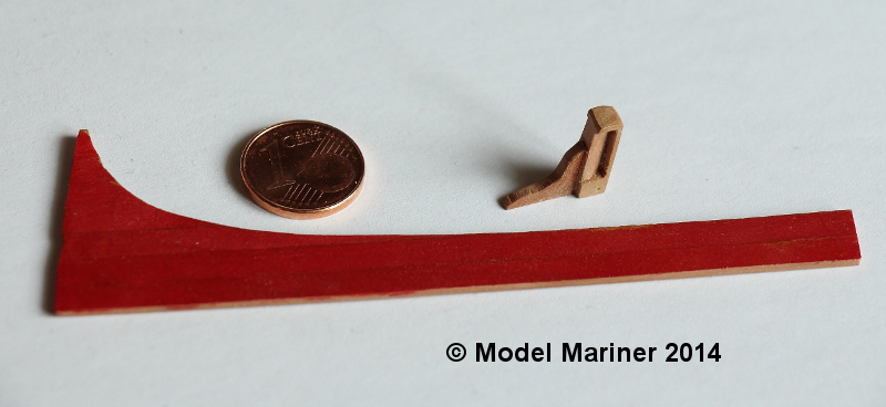
The most forward of the vertical supports of the head and the starboard side planking of the head.
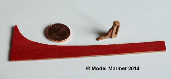
The vertical support (with it's knee) and the side planking will be glued on and the vertical timbers added afterwards.
The outside of the planking has been stained and painted prior to gluing on to the model.


Klaus
- Omega1234, yvesvidal, SawdustDave and 5 others
-
8
-
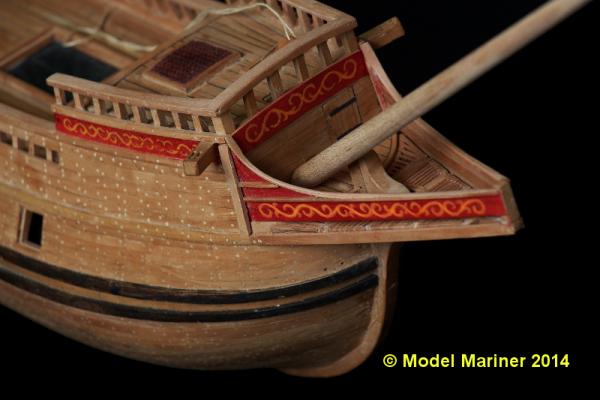
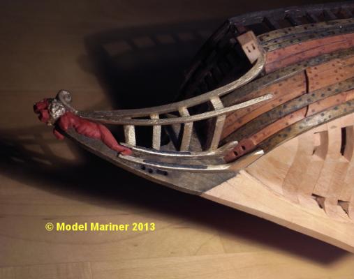
Thanks for the comments and likes
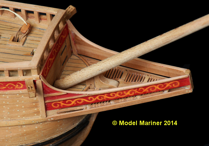
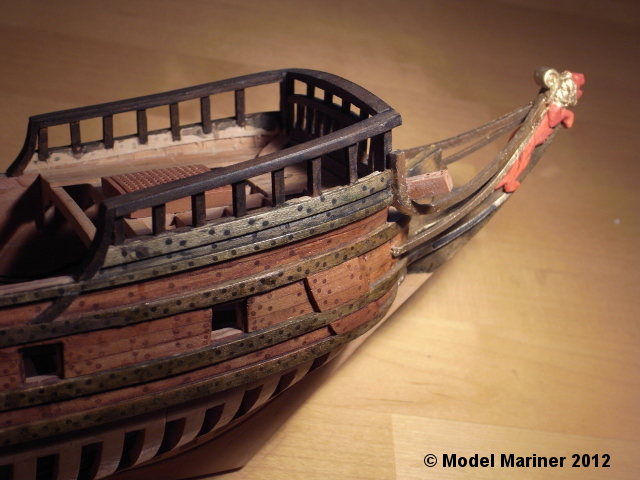
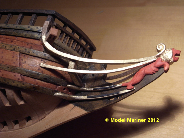
The figure head has been painted and glued on.
I have installed at first the headrails and then fitted the head timbers. Maybe it would have been better to do it in reverse, but this is how I did it:
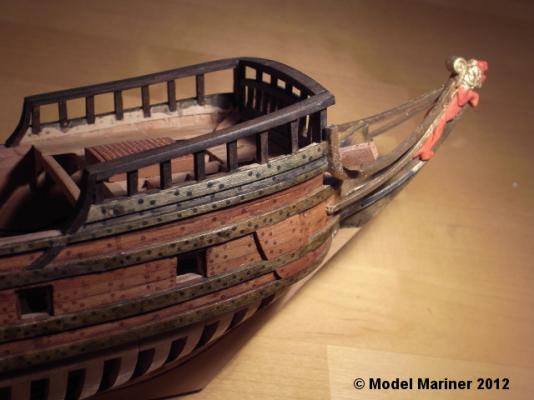
The first of the four head timbers is fitted:
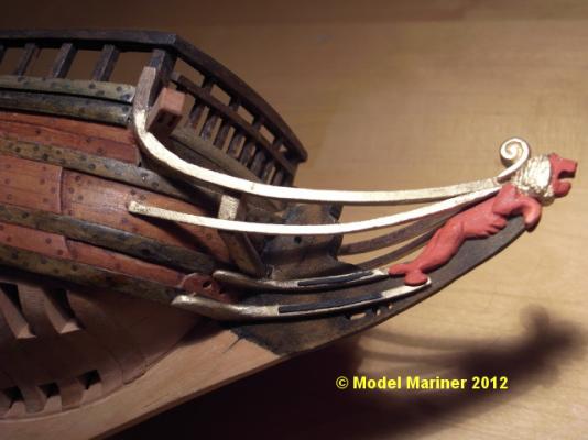
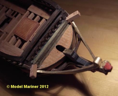
and the remaining ones are on:
Klaus
- GrandpaPhil, JPett, Dubz and 4 others
-
7
-
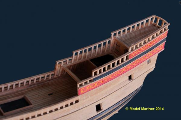
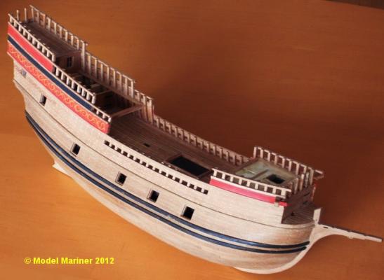
Thanks for the nice comments folks
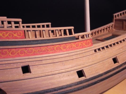
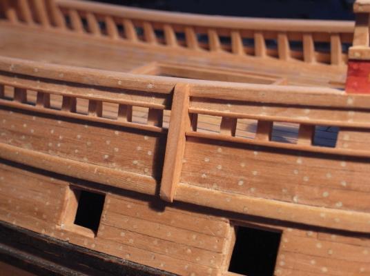
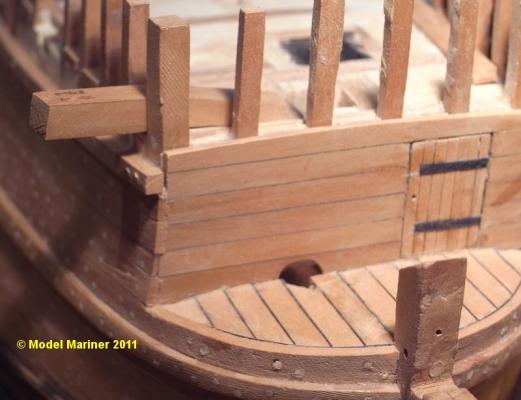
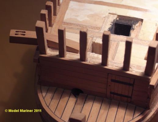
The railings at the stern and forecastle have been added. I glued chocks in between the top of all toptimbers and have glued on thin covering boards. I'm not sure what the correct English expression for these covering boards is, In some books they are called plansheer, in another planksheer and I've found also other names for them, Some times they are called rough tree rails - I'm rather confused.


Klaus
-
-
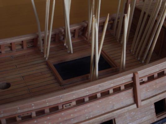
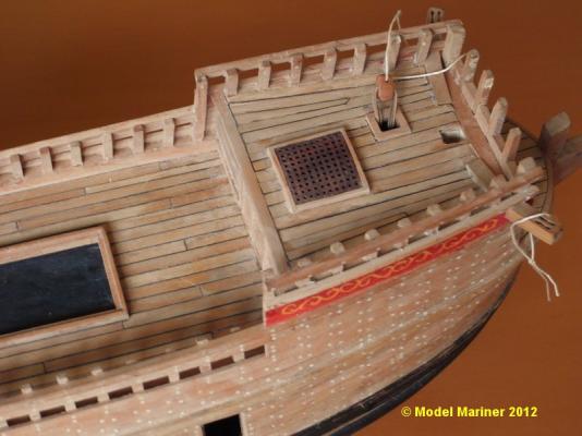
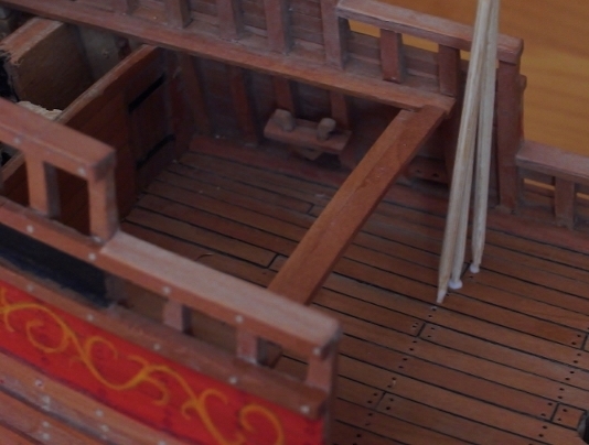
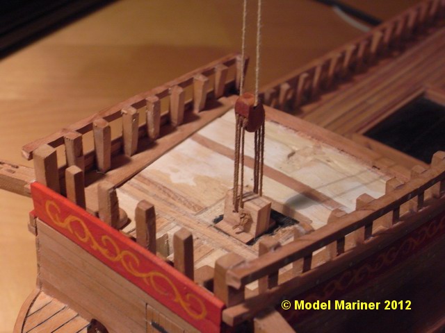
Forecastle deck:
Before planking the forecastle deck the dummy knight with rigged ramshead block and halyard (refer to post #9) has to be glued in: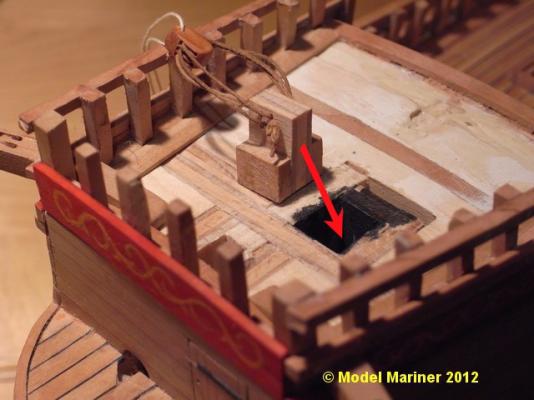
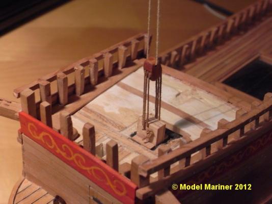
A piece of string (temporary) has been inserted into the upper hole in the ramshead block so that it can be pulled out later throught the small opening in the deck. This string will be replaced later by the fore yard tie.
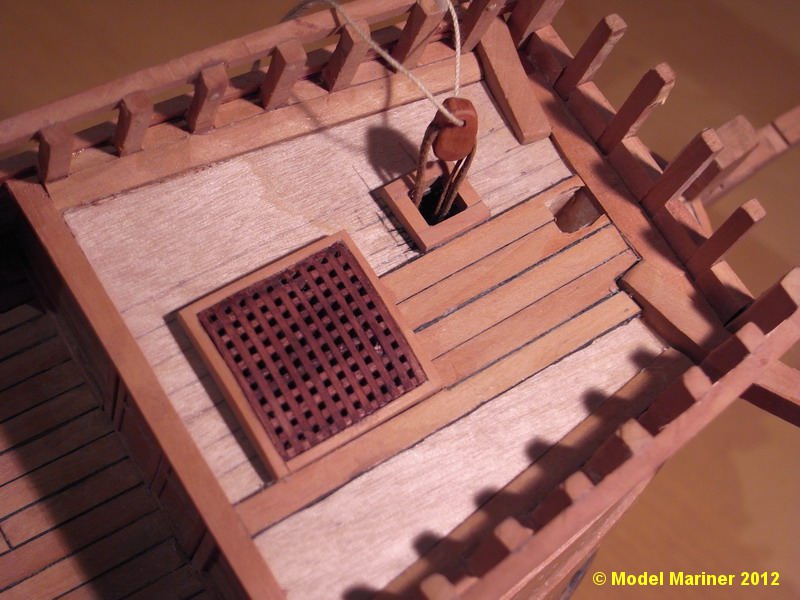
A false deck of 0.4 mm ply has been glued on, the coamings for the grating and the small opening for the halyard have been installed.

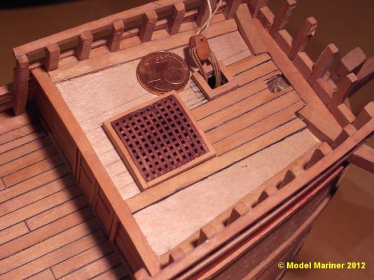
Planking is finished (except some required sanding and cleaning):
Klaus
- SawdustDave, CaptainSteve, davyboy and 4 others
-
7
-
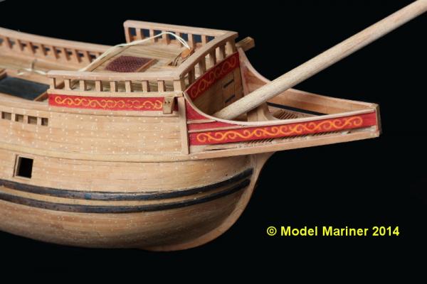
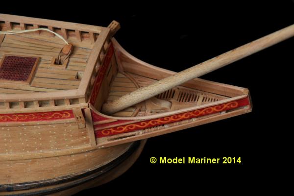
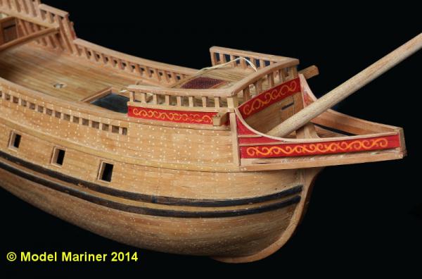
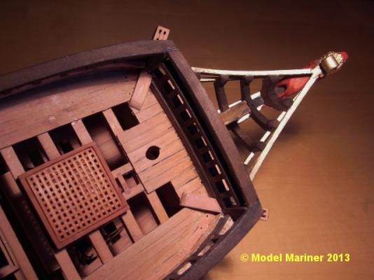
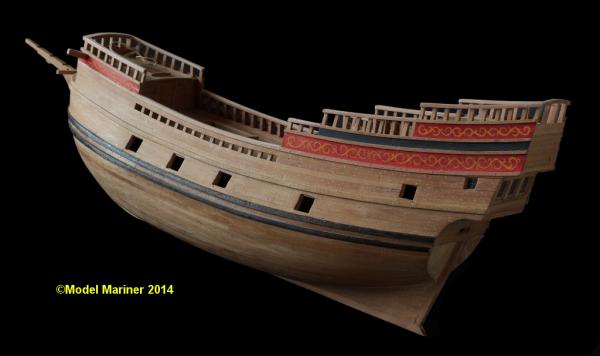
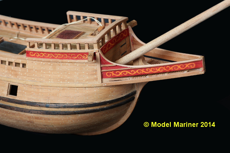
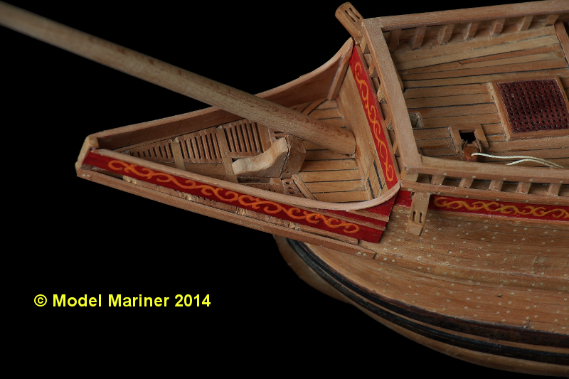
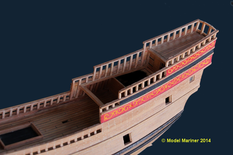
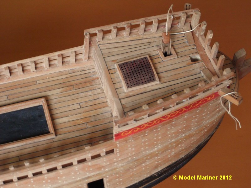
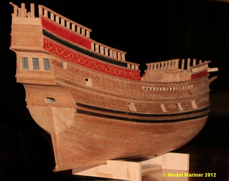
Thanks for the comments and likes
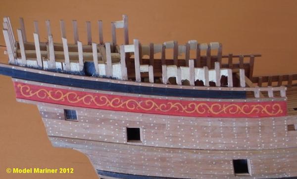
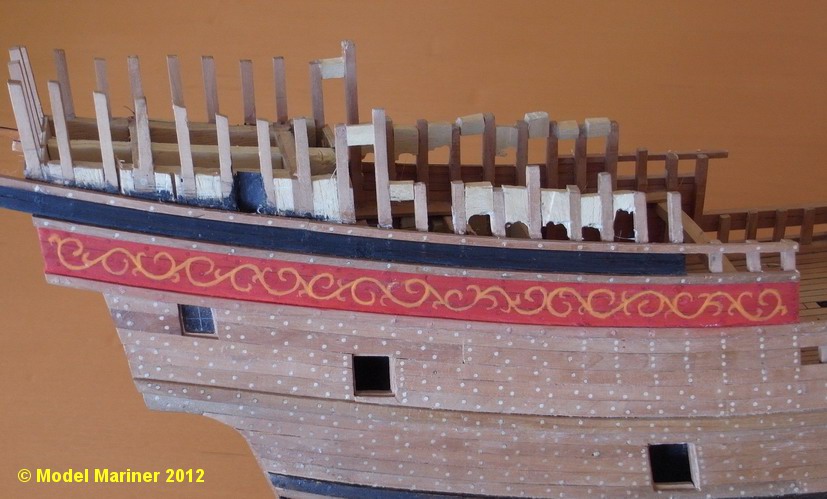
Now back to painting. What I have achieved is certainly not perfect, but I'm not unhappy with the result:
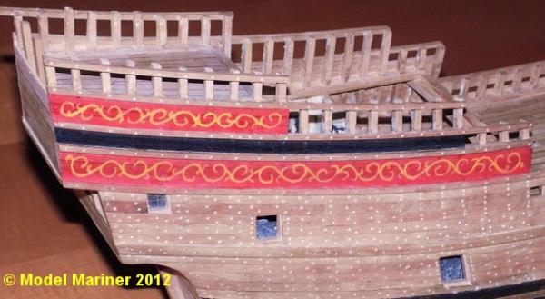

From a distance of a couple of feet I think it looks rather good, so I have put on a pinted board on top of the beakhead bulkhead as well:

Klaus
-
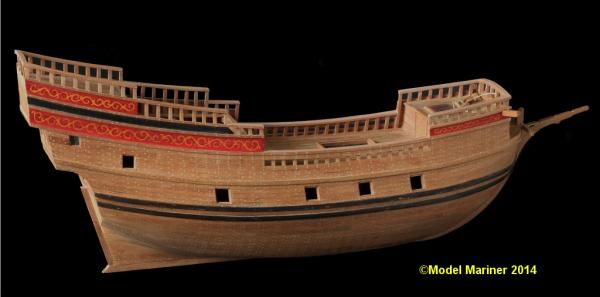
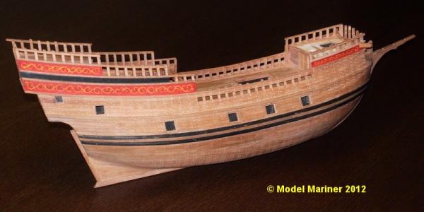
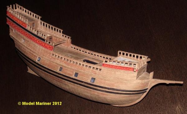
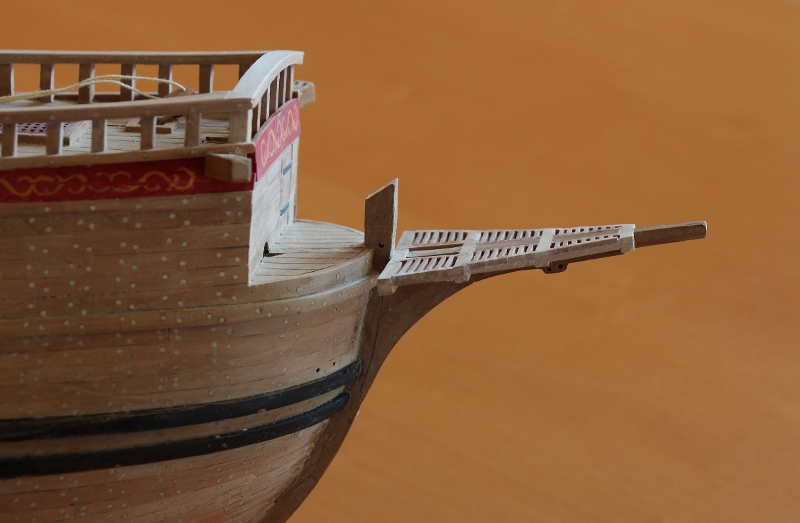
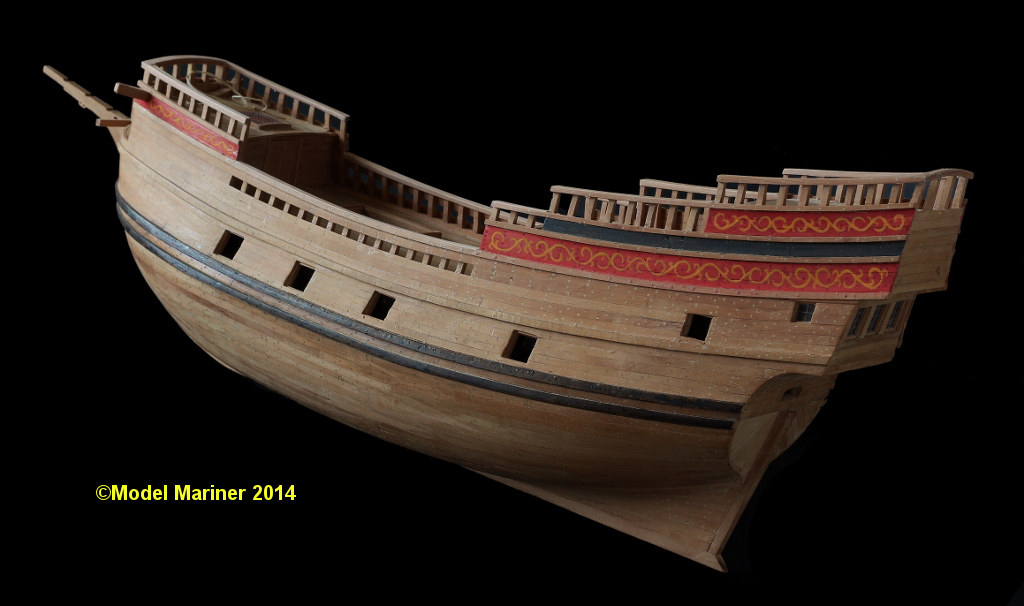
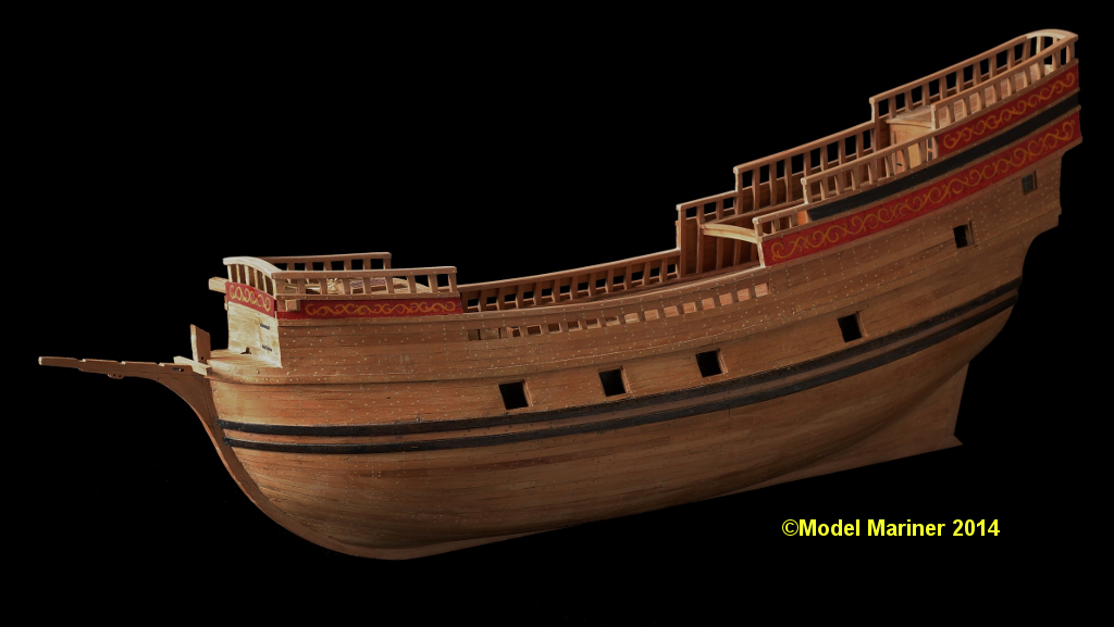
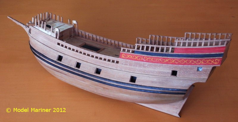
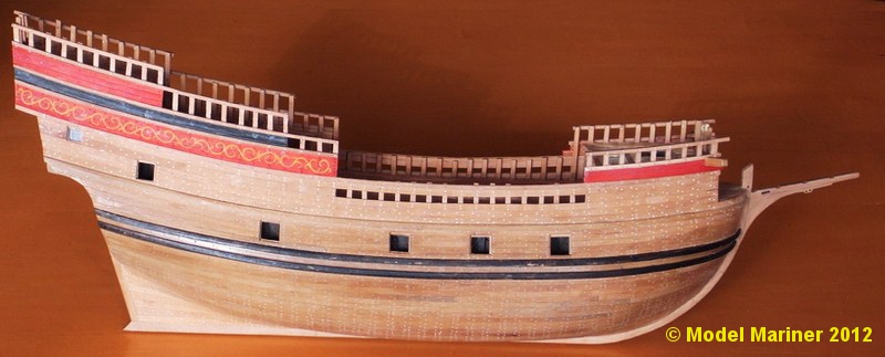
The catheads were made and glued onto the model:
2 more strakes of planking and a wale added:
The poop deck has been planked. Black paper has been used to imitate the caulking: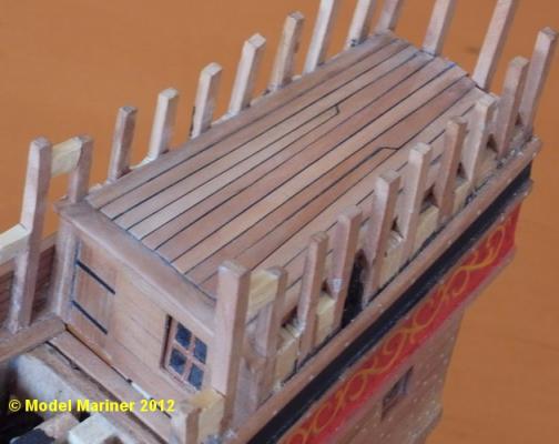
planking continued:

Planking of the ships side is finished:


Klaus
- Mirabell61, russ, Elmer Cornish and 3 others
-
6
-
....... – and when I've worked out how many actual strakes there are. I also have it in mind to contact the SL Foundation, for any extra information they have.
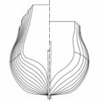
Regarding number of strakes:
I have the complete plan set of Statsraaden which you can buy from the stiftelsen in Bergen, but this does unfortunately not contain any cross section and the number of strakes can not be derived from the plan set but I trust the following will be helpful:
The following picture is a cross section of Statsraaden showing the number of strakes
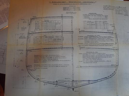
and was taken from a plan set of the ship displayed in the maritime museum in Bergen.
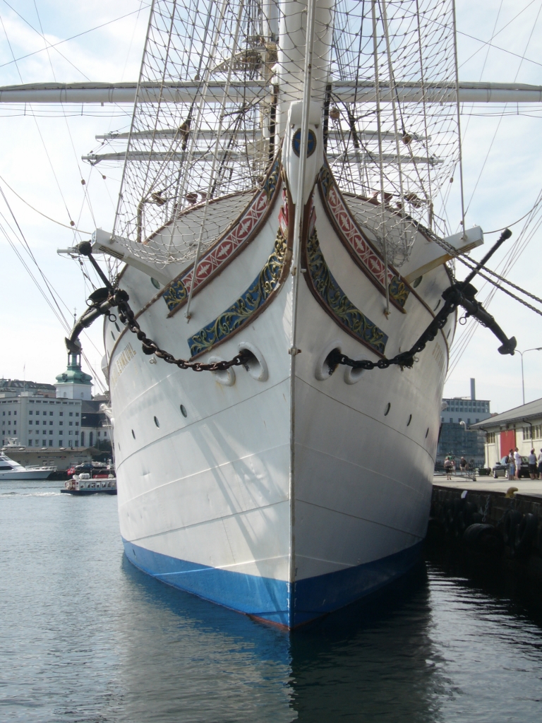
Bow view:

Stern view:
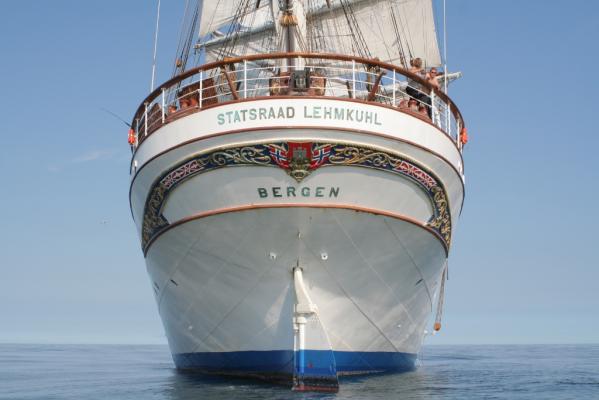
Somewhere I have one or two pictures of the ship in dry dock but have not yet found it
In case you need pictures of particular details of the ship send me a note, I might be able to help you
regards
Klaus
- Elmer Cornish, Mirabell61, egkb and 6 others
-
9


L'Amarante 1749 by giampieroricci - FINISHED - 1:30 - French Corvette
in - Build logs for subjects built 1501 - 1750
Posted
very nice work!
Klaus